OJFMA1500UHFMOBILEACCESS 1500 SYSTEM
Corning Optical Communication LLC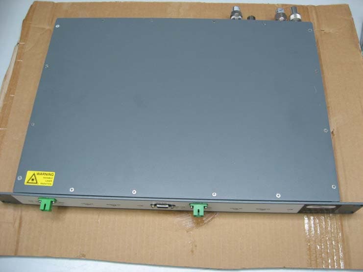
Click to zoom
Application Details
- Equipment Class
- TNB - Licensed Non-Broadcast Station Transmitter
- Date of Grant
- Feb 06, 2008
- Application Purpose
- Original Equipment
- Date of Application
- Feb 05, 2008
- Equipment Note
- MOBILEACCESS 1500 SYSTEM
- Frequency Range
- 406.11000000 - 511.90000000
- Country
- United States
Documents & Files
Document Text
Text extracted from the exhibit documents filed with the FCC. Open a document above to read the original.
Users Manual
P/N: 709C003001 REV: A0 Date: 30-DEC-07 M M M o o o b b b i i i l l l e e e A A A c c c c c c e e e s s s s s s 1 1 1 5 5 5 0 0 0 0 0 0 S S S y y y s s s t t t e e e m m m Installation and Configuration Guide Preface MA 1500 Installation and Configuration Guide II P P r r e e f f a a c c e e M M a a t t e e r r i i a a l l © COPYRIGHT 2006, MOBILEACCESS NETWORKS INC. ALL RIGHTS RESERVED. MOBILEACCESSTM IS A REGISTERED TRADEMARK OF MOBILEACCESS. THIS DOCUMENT CONTAINS OTHER TRADEMARKS, TRADE NAMES AND SERVICE MARKS OF MOBILEACCESS AND OTHER ORGANIZATIONS, ALL OF WHICH ARE THE PROPERTY OF THEIR RESPECTIVE OWNERS. THIS DOCUMENT CONTAINS CONFIDENTIAL AND PROPRIETARY INFORMATION OF MOBILEACCESS AND MAY NOT BE COPIED, TRANSMITTED, STORED IN A RETRIEVAL SYSTEM OR REPRODUCED IN ANY FORMAT OR MEDIA, IN WHOLE OR IN PART, WITHOUT THE PRIOR WRITTEN CONSENT OF MOBILEACCESS. INFORMATION CONTAINED IN THIS DOCUMENT SUPERSEDES ANY PREVIOUS MANUALS, GUIDES, SPECIFICATIONS, DATA SHEETS OR OTHER INFORMATION THAT MAY HAVE BEEN PROVIDED OR MADE AVAILABLE TO THE USER. THIS DOCUMENT IS PROVIDED FOR INFORMATIONAL PURPOSES ONLY, AND MOBILEACCESS DOES NOT WARRANT OR GUARANTEE THE ACCURACY, ADEQUACY, QUALITY, VALIDITY, COMPLETENESS OR SUITABILITY FOR ANY PURPOSE OF THE INFORMATION CONTAINED IN THIS DOCUMENT. MOBILEACCESS RESERVES THE RIGHT TO MAKE UPDATES, IMPROVEMENTS AND ENHANCEMENTS TO THIS DOCUMENT AND THE PRODUCTS TO WHICH IT RELATES AT ANY TIME WITHOUT PRIOR NOTICE TO THE USER. MOBILEACCESS MAKES NO WARRANTIES, EXPRESS OR IMPLIED, INCLUDING, WITHOUT LIMITATION, THOSE OF MERCHANTABILITY AND FITNESS FOR A PARTICULAR PURPOSE, WITH RESPECT TO THIS DOCUMENT OR ANY INFORMATION CONTAINED HEREIN. MobileAccess, 8391 Old Courthouse Road, Suite 300, Vienna, VA 22182 Tel: (866)436-9266, (703)848-0200 TAC: (800)787-1266, Fax: (703)848-0280 http://www.MobileAccess.com Preface MA 1500 Installation and Configuration Guide III Policy for Warrantee and Repair MOBILEACCESS TESTS AND INSPECTS ALL ITS PRODUCTS TO VERIFY THEIR QUALITY AND RELIABILITY. MOBILEACCESS USES EVERY REASONABLE PRECAUTION TO ENSURE THAT EACH UNIT MEETS THEIR DECLARED SPECIFICATIONS BEFORE SHIPMENT. CUSTOMERS SHOULD ADVISE THEIR INCOMING INSPECTION, ASSEMBLY, AND TEST PERSONNEL ABOUT THE PRECAUTIONS REQUIRED IN HANDLING AND TESTING OUR PRODUCTS. MANY OF THESE PRECAUTIONS CAN BE FOUND IN THIS MANUAL. THE PRODUCTS ARE COVERED BY THE FOLLOWING WARRANTIES: General Warranty MOBILEACCESS WARRANTS TO THE ORIGINAL PURCHASER ALL STANDARD PRODUCTS SOLD BY MOBILEACCESS TO BE FREE OF DEFECTS IN MATERIAL AND WORKMANSHIP FOR ONE (1) YEAR FROM DATE OF SHIPMENT FROM MOBILEACCESS. DURING THE WARRANTY PERIOD, MOBILEACCESS WILL REPAIR OR REPLACE ANY PRODUCT THAT MOBILEACCESS PROVES TO BE DEFECTIVE. THIS WARRANTY DOES NOT APPLY TO ANY PRODUCT THAT HAS BEEN SUBJECT TO ALTERATION, ABUSE, IMPROPER INSTALLATION OR APPLICATION, ACCIDENT, ELECTRICAL OR ENVIRONMENTAL OVER-STRESS, NEGLIGENCE IN USE, STORAGE, TRANSPORTATION OR HANDLING. Specific Product Warranty Instructions ALL MOBILEACCESS PRODUCTS ARE WARRANTED AGAINST DEFECTS IN WORKMANSHIP, MATERIALS AND CONSTRUCTION, AND TO NO FURTHER EXTENT. ANY CLAIM FOR REPAIR OR REPLACEMENT OF UNITS FOUND TO BE DEFECTIVE ON INCOMING INSPECTION BY A CUSTOMER MUST BE MADE WITHIN 30 DAYS OF RECEIPT OF SHIPMENT, OR WITHIN 30 DAYS OF DISCOVERY OF A DEFECT WITHIN THE WARRANTY PERIOD. THIS WARRANTY IS THE ONLY WARRANTY MADE BY MOBILEACCESS AND IS IN LIEU OF ALL OTHER WARRANTIES, EXPRESSED OR IMPLIED. MOBILEACCESS SALES AGENTS OR REPRESENTATIVES ARE NOT AUTHORIZED TO MAKE COMMITMENTS ON WARRANTY RETURNS. Returns IN THE EVENT THAT IT IS NECESSARY TO RETURN ANY PRODUCT AGAINST ABOVE WARRANTY, THE FOLLOWING PROCEDURE SHALL BE FOLLOWED: 1. RETURN AUTHORIZATION IS TO BE RECEIVED FROM MOBILEACCESS PRIOR TO RETURNING ANY UNIT. ADVISE MOBILEACCESS OF THE MODEL, SERIAL NUMBER, AND DISCREPANCY. THE UNIT MAY THEN BE FORWARDED TO MOBILEACCESS, TRANSPORTATION PREPAID. DEVICES RETURNED COLLECT OR WITHOUT AUTHORIZATION MAY NOT BE ACCEPTED. 2. PRIOR TO REPAIR, MOBILEACCESS WILL ADVISE THE CUSTOMER OF OUR TEST RESULTS AND ANY CHARGES FOR REPAIRING CUSTOMER-CAUSED PROBLEMS OR OUT-OF-WARRANTY CONDITIONS ETC. 3. REPAIRED PRODUCTS ARE WARRANTED FOR THE BALANCE OF THE ORIGINAL WARRANTY PERIOD, OR AT LEAST 90 DAYS FROM DATE OF SHIPMENT. Limitations of Liabilities MOBILEACCESS'S LIABILITY ON ANY CLAIM, OF ANY KIND, INCLUDING NEGLIGENCE FOR ANY LOSS OR DAMAGE ARISING FROM, CONNECTED WITH, OR RESULTING FROM THE PURCHASE ORDER, CONTRACT, QUOTATION, OR FROM THE PERFORMANCE OR BREACH THEREOF, OR FROM THE DESIGN, MANUFACTURE, SALE, DELIVERY, INSTALLATION, INSPECTION, OPERATION OR USE OF ANY EQUIPMENT COVERED BY OR FURNISHED UNDER THIS CONTACT, SHALL IN NO CASE EXCEED THE PURCHASE PRICE OF THE DEVICE WHICH GIVES RISE TO THE CLAIM. EXCEPT AS EXPRESSLY PROVIDED HEREIN, MOBILEACCESS MAKES NO WARRANTY, EXPRESSED OR IMPLIED, WITH RESPECT TO ANY GOODS, PARTS AND SERVICES PROVIDED IN CONNECTION WITH THIS AGREEMENT INCLUDING, BUT NOT LIMITED TO, THE IMPLIED WARRANTIES OF MERCHANTABILITY AND FITNESS FOR A PARTICULAR PURPOSE. MOBILEACCESS SHALL NOT BE LIABLE FOR ANY OTHER DAMAGE INCLUDING, BUT NOT LIMITED TO, INDIRECT, SPECIAL OR CONSEQUENTIAL DAMAGES ARISING OUT OF OR IN CONNECTION WITH FURNISHING OF GOODS, PARTS AND SERVICE HEREUNDER, OR THE PERFORMANCE, USE OF, OR INABILITY TO USE THE GOODS, PARTS AND SERVICE. Preface MA 1500 Installation and Configuration Guide IV Reporting Defects THE UNITS WERE INSPECTED BEFORE SHIPMENT AND FOUND TO BE FREE OF MECHANICAL AND ELECTRICAL DEFECTS. EXAMINE THE UNITS FOR ANY DAMAGE THAT MAY HAVE BEEN CAUSED IN TRANSIT. IF DAMAGE IS DISCOVERED, FILE A CLAIM WITH THE FREIGHT CARRIER IMMEDIATELY. NOTIFY MOBILEACCESS AS SOON AS POSSIBLE. NOTE: KEEP ALL PACKING MATERIAL UNTIL YOU HAVE COMPLETED THE INSPECTION WARNING: TO COMPLY WITH FCC RF EXPOSURE COMPLIANCE REQUIREMENTS, ANTENNAS USED FOR THIS PRODUCT MUST BE FIXED MOUNTED ON INDOOR PERMANENT STRUCTURES, PROV…
Text truncated - open the document above for the full version.
Cover Letter(s)
Making Wireless an Indoor State of Mind FCC Confidential Authorization Date: 01/27/08 FEDERAL COMMUNICATIONS COMMISSIONS Authorization and Evaluation Division 7435 Oakland Mills Road Columbia, MD 21046 Subject: Confidentiality Request regarding application for certification of FCC ID: OJFMA1500UHF In accordance with Sections 0.457 and 0.459 of the Commission’s Rules, MobileAccess Networks hereby requests long-term confidential treatment of information accompanying this application as outlined below: Conf MA 1500 System BlkDia.pdf Conf UHF-1500-BU-2 PartsLst.pdf Conf UHF-1500-RU PartsLst.pdf Conf MA 1500 System Schem.pdf The above materials contain proprietary and confidential information not customarily released to the public. The public disclosure of these materials provides unjustified benefits to its competitors in the market. Sincerely, Steve Blum Product Manager MobileAccess Networks 8391 Old Courthouse Rd Suite 300 Vienna VA 22182-3819 Unwired: 541-758-2880 Making Wireless an Indoor State of Mind On the web at www.MobileAccess.com
Cover Letter(s)
I.T.L (PRODUCT TESTING) Ltd. HEAD OFFICE, SAFETY & TELECOMS LABS. EMC LABORATORY 1 Batsheva St. POB: 87 Kfar Bin Nun 99780 Lod 71100 ISRAEL ISRAEL Tel. 972-8-915300 Tel. 972-8-9797799 Fax. 972-8-915301 Fax. 972-8-9797702 Email: [email protected], Web Site: http://www.itl.co.il To: Timco Engineering From: Shaike Raz Att: Reviewing Engineer Reference No: L77450.00 Date: 28 January 2008 Subject: FCC ID Application for Mobile Access Networks MobileAccess 1500 System FCC ID: OJFMA1500UHF To Whom it May Concern, 1. The subject product consists of 3 units: 1500-UHF-BU-2, 1500-UHF-BU-1, and 1500-UHF-RU. Testing was performed on the 1500-UHF-BU-2 and 1500-UHF-RU. 2. The 1500-UHF-RU can be used with either the 1500-UHF-BU-2 or the 1500- UHF-B1. 3. See customer’s declaration in ITL test report no. E77450.00 concerning the differences between the 1500-UHF-BU-2 and the 1500-UHF-BU-1. 4. The 1500-UHF-BU-2 and 1500-UHF-BU-1 uses the same housing and the location of the FCC label is identical for both units. 5. The FCC label is the identical for all 3 units. 6. All 3 units use the same optical card. Please contact me if you need any additional information. Regards Shaike Raz EMC Laboratory Manager EMC Laboratory ITL (Product Testing) Ltd. Kfar Bin Nun Israel Tel: +972-8-915-3100 Ext 217 Fax: +972-8-915-3101 Email: [email protected] http://www.itl.co.il
Cover Letter(s)
Making Wireless an Indoor State of Mind FCC Confidential Authorization Date: 01/27/2008 To: Timco Engineering Inc. To Whom It May Concern We hereby authorize Mr. Shaike Raz of I.T.L. (Product Testing) Ltd (ITL) to act on our behalf regarding the FCC ID Certification Process for the following application: MA 1500 System FCC ID: OJFMA1500UHF Thank you, Sincerely, Steve Blum Product Manager MobileAccess Networks 8391 Old Courthouse Rd Suite 300 Vienna VA 22182-3819 Unwired: 541-758-2880 Making Wireless an Indoor State of Mind On the web at www.MobileAccess.com
External Photos
1500-UHF-BU-2 Bottom View 1500-UHF-BU-2 Side 1 View 1500-UHF-BU-2 Front View 1500-UHF-BU-2 Rear View 1500-UHF-BU-2 Side 2 View 1500-UHF-BU-2 Side 2 View 1500-UHF-RU Bottom View 1500-UHF-RU Side 1 View 1500-UHF-RU Front View 1500-UHF-RU Rear View 1500-UHF-RU Side 2 View 1500-UHF-RU Top View
ID Label/Location Info
TITLE: DrawnBy: YaakovS. YossiG. Name:Signature: Date: Check: Approve: MA1K,FCCLABELFOR1500UHF OfekOneCenter,BuildingB.NorthernIndusrialZone.Lod71293 PRODUCTP/N: DrawingNo: Rev:A00 PaperSize:A4 Sh:1of1 MobileAccessLtd. Thisdocumentcontain proprietary informationand isthepropertyof MobileAccessLtd.Nouse, Disclosureorreproduction isgrantedtoanythirdparties withoutexplicitwritten permissionof confidential Ltd.MobileAccess REVISIONS REV. DESCRIPTION DATEAPPROVED ECONo: NOTES: 1.ALLTEXTPRINTEDSIZE7ANDFONTSTYLETIMESNEWROMAN. 2.POSITIONCOMPANYLOGOACCORDINGTODIMENSIONSPECIFIED. AlonaM. 2)Thisdevicemustacceptanyinterferencereceived, ThisdevicecomplieswithPart15oftheFCCRules. Operationissubjecttothefollowingtwoconditions: 1)Thisdevicemaynotcauseharmfulinterference,and operation. includinginterferencethatmaycauseundesired FCCID:OJFMA1500UHF YaakovS. YossiG. AlonaM.
ID Label/Location Info
FCC Label FCC Label Location on 1500-UHF-BU-2 Note: Location is the same on 1500-UHF-BU-1 FCC Label FCC Label Location on 1500-UHF-RU
Internal Photos
1500-UHF-BU-2 PCB’s in Case 1500-UHF-BU-2 Optical card With Laser Side 1 1500-UHF-BU-2 Optical card With Laser Side 2 1500-UHF-BU-2 Optical Card Side 1 1500-UHF-BU-2 Optical Card Side 2 1500-UHF-BU-2 DC Card Side 1 1500-UHF-BU-2 DC Card Side 2 1500-UHF-BU-2 Filter Side 1 1500-UHF-BU-2 Filter Side 2 1500-UHF-RU PCB’s In Case 1500-UHF-RU Optical card With Laser Side 1 1500-UHF-RU Optical card With Laser Side 2 1500-UHF-RU Optical Card Side 1 1500-UHF-RU Optical Card Side 2 1500-UHF-RU DC Card Side 1 1500-UHF-RU DC Card Side 2
Operational Description
I I n n t t r r o o d d u u c c t t i i o o n n t t o o t t h h e e M M A A 1 1 5 5 0 0 0 0 S S y y s s t t e e m m MA 1500 provides a cost effective solution for extending 450 MHz signal from a single BTS location to remote locations, up to 20 Km away, over SM F/O connections. Simplex RF inputs and outputs support a wide variety of channel assignments, while maintaining the service integrity via highly linear amplifiers. Intuitive GUI software enables end-to-end setup and adjustment of the coverage to minimize interaction with outdoor signals. The MA-1500 system is based on the following elements: • 1500-BU – A 1500-BU unit is installed, adjacent to the BTS location. It performs the RF to optic signal conversion at the BTS side and transmits the services to the remote location(s) where 1500-RU units are installed. • 1500-RU – A 1500-RU is installed at each remote location. This unit reconverts the signals received over the optic fiber to RF and distributes the services to the connected antennas. • MA-1500 GUI Tool – Intuitive GUI used for setting up, adjusting and monitoring the MA 1500 system. 1 System Architecture At the Main building, the 1500-UH-BU interfaces to the BTS via passive interface. It converts the RF signal received from the BTS to an optic signal and transmits it over SM optic fiber to the MA 1500 Remote. At the Remote buildings, the 1500-UHF-RU reconverts the received RF signal to an optic signal and routes the RF signals to the antennas. The MA-1500 system provides flexible solutions for two types of antennas – simplex and duplex. Both solutions are illustrated in the figure below 450 MHz Repeater or BTS TX/RX Figure 2. Duplexer 1.5 MHz BW 2.5 MHz sep >50 dB Isolation Interface Tray TX RX >50' Figure 1. Simplex antennas with 50' spatial separation Figure 3. Local support via ½” coaxial cable Remote Locations Head End One strand single mode fiber 1500-UHF-BU 1500-UHF-BU 1500-UHF-RU 1500-UHF-RU Figure. MA 1500 Installations
Test Report
Cert. No. 1152.01 Electrical (EMC) DATE: 27 January 2008 I.T.L. (PRODUCT TESTING) LTD. FCC EMC/Radio Test Report for Mobile Access Networks Equipment under test: MobileAccess 1500 System 1. 1500-UHF-BU-2 2. 1500-UHF-RU Written by: _____________________________ D. Shidlowsky, Documentation Approved by: _____________________________ E. Pitt, Test Engineer Approved by: _____________________________ I. Raz, EMC Laboratory Manager This report must not be reproduced, except in full, without the written permission of I.T.L. (Product Testing) Ltd. This report relates only to items tested. Test Report E77450.00 Mobile Access Networks Page 1 of 64 FCC ACC M Ver 1.1 05Mayl 2000 Cert. No. 1152.01 Electrical (EMC) Measurement/Technical Report for Mobile Access Networks MobileAccess 1500 System 1. 1500-UHF-BU-2 2. 1500-UHF-RU FCC ID:OJFMA1500UHF 27 January 2008 This report concerns: Original Grant X Class II change: Class B verification Class A verification Class I change Equipment type: Licensed Non-Broadcast Station Transmitter Request Issue of Grant: x Immediately upon completion of review Limits used: CISPR 22 Parts 2; 15, 90 x Measurement procedure used is ANSI C63.4-2003. Substitution Method used as in ANSI/TIA-603-B: 2002 Application for Certification Applicant for this device: prepared by: (different from "prepared by") Application for Certification Applicant for this device: prepared by: (different from "prepared by") Ishaishou Raz Steve Blum ITL (Product Testing) Ltd. Mobile Access Networks Kfar Bin Nun 8391 Old Courthouse Rd., Suite #300 D.N. Shimshon 99780 Vienna, VA. 22182 Israel U.S.A. e-mail [email protected] Tel: +1-541-758-2880 Fax: +1-703-848-0260 e-mail: [email protected] Test Report E77450.00 Mobile Access Networks Page 2 of 64 FCC ACC M Ver 1.1 05Mayl 2000 TABLE OF CONTENTS 1. GENERAL INFORMATION-------------------------------------------------------------------------------5 1.1 Administrative Information.................................................................................5 1.2 List of Accreditations.........................................................................................8 1.3 Product Description...........................................................................................9 1.4 Test Methodology..............................................................................................9 1.5 Test Facility.......................................................................................................9 1.6 Measurement Uncertainty.................................................................................9 2. PRODUCT LABELING-----------------------------------------------------------------------------------10 3. SYSTEM TEST CONFIGURATION--------------------------------------------------------------------12 3.1 Justification......................................................................................................12 3.2 EUT Exercise Software...................................................................................12 3.3 Special Accessories........................................................................................12 3.4 Equipment Modifications.................................................................................12 3.5 Configuration of Tested System......................................................................13 4. BLOCK DIAGRAM-----------------------------------------------------------------------------------------14 4.1 Schematic Block/Connection Diagram............................................................14 4.2 Theory of Operation ........................................................................................14 5. TEST SET-UP PHOTOS----------------------------------------------------------------------------------16 6. PEAK OUTPUT POWER---------------------------------------------------------------------------------18 6.1 Test procedure................................................................................................18 6.2 Results table....................................................................................................20 6.3 Test Equipment Used......................................................................................21 7. OCCUPIED BANDWIDTH-------------------------------------------------------------------------------22 7.1 Test Procedure................................................................................................22 7.2 Results Table..................................................................................................25 7.3 Test Equipment Used......................................................................................26 8. EMISSION MASK------------------------------------------------------------------------------------------27 8.1 Test Specification............................................................................................27 8.2 Test Procedure................................................................................................27 8.3 Results.............................................................................................................29 8.4 Test Equipment Used......................................................................................29 9. OUT OF BAND EMISSIONS AT ANTENNA TERMINALS--------------------------------------30 9.1 Test Specification............................................................................................30 9.2 Test procedure................................................................................................30 9.3 Results table....................................................................................................43 9.4 Test Equipment Used......................................................................................44 10. OUT OF BAND EMISSIONS (RADIATED)----------------------------------------------------------45 10.1 Test Specification.....................................…
Text truncated - open the document above for the full version.
Test Setup Photos
Test Set-up Photos Figure 1. Radiated Emission Test Figure 2. Radiated Emission Test Figure 3. Conducted Emission From Antenna Ports Tests Figure 4. Conducted Emission From Antenna Ports Tests
Contact Information
Applicant
Dana Whitney(Director of Operations and Program)
Test Firm
Israel Testing LaboratoriesIIan Cohen
Technical Specifications
| # | Rule Parts | Frequency Range | Power Output | Emission | Tolerance |
|---|---|---|---|---|---|
| 1 | 90.210 | 406.11 MHz - 511.9 MHz | 28.50 mW | F3E | Amp |
Other Applications from Corning Optical Communication LLC

OJFE62-N3-7US
Aug 29, 2024Remote Unit, Radio Node
Equipment Class
B2I - Part 20 Industrial Booster (CMRS)
OJFDHRU-G2-19
Apr 09, 2024HRU Digital High Power Amplifier Module supporting PCS
Equipment Class
B2I - Part 20 Industrial Booster (CMRS)
OJFDLRUG2678
Oct 17, 2023Low Band dRAU
Equipment Class
B2I - Part 20 Industrial Booster (CMRS)
OJFDMRUG22325
Jul 31, 2023digital Medium-power Remote Unit
Equipment Class
B2I - Part 20 Industrial Booster (CMRS)
OJFDMRUG2678
Jul 30, 2023digital Medium-power Remote Unit
Equipment Class
B2I - Part 20 Industrial Booster (CMRS)