OJFMA2000In-Building RF Distribution Sytem
Corning Optical Communication LLC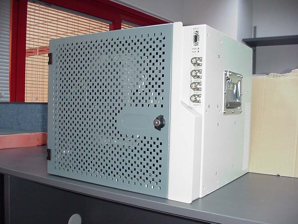
Click to zoom
Application Details
- Equipment Class
- PCB - PCS Licensed Transmitter
- Date of Grant
- Nov 15, 2004
- Application Purpose
- Original Equipment
- Date of Application
- Nov 15, 2004
- Equipment Note
- In-Building RF Distribution Sytem
- Frequency Range
- 928.00000000 - 941.00000000
- Country
- United States
Documents & Files
Document Text
Text extracted from the exhibit documents filed with the FCC. Open a document above to read the original.
Users Manual
DS-2000 Rev 2.7 Features • Support for remote monitoring through MA 410/430 controllers • Scalable and future-safe – additional remote units can easily be installed • All active components are located in the communication closet/room BTS 3 BTS 2 BTS 1 BTS 2 BTS 1 RIU 2 MA 410 RIU 1 MA 430 Base Unit Base Unit RU 2000 RU 2000 Add-on RU 2000 Add-on RU 2000 Remote Cabinet 1 Remote Cabinet 8 Remote Monitoring BU Servicing up to eight remote locations Antennas distributing all services in the remote locutions Antennas distributing all services in the remote locutions MobileAccess 2000 MobileAccess 2000 mobileaccess Networks Providing converged wireless coverage solutions MobileAccess™ 2000 converged wireless networks solution provides scalable in-building coverage for multiple wireless data and voice services through a single coax and broadband antenna infrastructure. The solution is based on two main elements that are interconnected via fiber optic cable: • Remote Cabinets - distributed over remote sites, the remote cabinets interface to the coax antenna infrastructure. Each cabinet can house up to five Remote Units (RUs) 2000 corresponding to the covered services. MA 2000 Lite provides single operator entry level support. • Base Units - concentrated in the telecom room, the BUs interface to the RF signal source, where each BU performs RF to optic conversion for a number of operator services. Each BU can support up to eight same service RUs. In addition, Remote Interface Units (RIUs) can be used to provide interface to the each BTS, and automatically adjust the output signal to respond to a range of BTS or BDA output power levels. MA 410/430 controllers can be used for remote monitoring of the system elements from a single location via advanced intuitive GUI. • Each Remote Cabinet can support up to 20 multi- operator services • Each MA 2000 Lite can support up to 8 services • All services are distributed through a single coax and antenna infrastructure • Support for high-power modules • Support for all current and future technologies such as TDMA, CDMA, WCDMA and GSM, and services such as PCS/CELLULAR, Paging, iDEN and 802.11 (a/b/g) Wireless LAN Example of MA 2000 system with remote cabinets supporting up to five services: two per RU 2000 and an additional service provided by the Add- on unit. A single coax and antenna infrastructure services each remote location. Each BU can distribute the signal over up to eight remote locations DS-2000 Rev 2.7 MobileAccess 2000 RF Connections To RF source (Base Unit and RIU): N-type Female, 50 ohm To antennas: N-type Female, 50 ohm Intermodule:SMA Female, 50 ohm Physical Specification Dimensions - Base Unit 48.26x4.44x29.97cm (19”x1Ux11.8”) - RC (H x W x D) 355x482.6x397mm (13.97”x19”x15.63”) - Radio Interface Unit 48.26x13.32x29.97cm (19”x3Ux11.8”) - MA 410/430 48.26x4.44x29.97cm (19”x1Ux11.8”) Weight - BU 2.82Kg (6.2lb) - RC 2000 (chassis)35 Kg four modules (77lbs) - RIU (3 BTSC) 8.7Kg (19lb) - MA 410/430 2.6Kg (5.8lb) Environmental Specifications Temperature Operating0ºC to +50ºC (32ºF to 122ºF) Storage-20ºC to 85ºC (-4ºC to 185ºC) Standards and Approvals USA - FCC-47CFR, parts 2,15, 22, 24,90 Canada - IC Supported Services TDMA 800/1900 CDMA 800/1800/1900 GSM 900/1800/1900 iDEN 800, SMR 900, Paging 900 WCDMA Fiber Optic Specifications Optical output power 1.0mW Max. Optical budget 3dB Optical loss per mated-pair connectors: 0.5dB (max) Optical ConnectorSC/APC Fiber type9/125 SM Wavelength1310 10nm Maximum distance between Base Unit and Remote Cabinet2Km Power Supply to Base Units, Remote Unit 2000, RIUs and MA 410/430:20-48VDC Supply to 1200 add-on:25-48VDC Consumption: - RC chassis20W - Base Unit 14W - Remote Unit 200025W - Add-on MA 120050W - RIU12W - MA 410/43010W MA 410/430 Remote Management - Remote SNMP management from a single location - Client/server management capability over TCP/IP network with enhanced monitoring and control capabilities - Intuitive GUI that enables end-to-end fault sourcing from RIU to antennas - GUI includes: - System status at a glance through multi-color tree with upward propagation of fault indications - Graphical view of system elements including LED status displays and auxiliary connections - Multi-color event monitoring display 464.0 [18.3"] 482.6 [19.0"] 101.6 [4.0"] 76.2 [3.0"] 101.6 [4.0"] 355.0 [14.0"] 431.6 [17.0"] 349.4 [13.8"] 397.0 [15.6"] 355.0 [13.98"] 302.0 [11.89"] 459.6 [18.09"] 487.6 [19.20"] 349.4 [13.76"] 397.0 [15.63"] 460.0 [18.11"] DS-2000 Rev 2.7 MobileAccess 2000 Wallmount Cabinet Rackmount Cabinet
Users Manual
MobileAccess™ 2000 System Installation and Configuration Guide UM 2000, Rev 1.1 October, 2004 Preface MobileAccess 2000 MobileAccess 2000 MobileAccess Ltd. Vienna, Virginia Tel: +1-703-848-0200 MobileAccess Ltd. Lod, Israel Tel: +972-8-9183888 http://www.MobileAccess.com Email: [email protected] Copyright © 2004 MobileAccess. © 2004 by MobileAccess This document contains confidential and proprietary information of MobileAccess and may not be copied, transmitted, stored in a retrieval system or reproduced in any format or media, in whole or in part, without the prior written consent of MobileAccess. Information contained in this document supersedes any previous manuals, guides, specifications, data sheets or other information that may have been provided or made available to the user. This document is provided for informational purposes only, and MobileAccess does not warrant or guarantee the accuracy, adequacy, quality, validity, completeness or suitability for any purpose of the information contained in this document. MobileAccess reserves the right to make updates, improvements and enhancements to this document and the products to which it relates at any time without prior notice to the user. MOBILEACCESS MAKES NO WARRANTIES, EXPRESS OR IMPLIED, INCLUDING, WITHOUT LIMITATION, THOSE OF MERCHANTABILITY AND FITNESS FOR A PARTICULAR PURPOSE, WITH RESPECT TO THIS DOCUMENT OR ANY INFORMATION CONTAINED HEREIN. TRADEMARK ACKNOWLEDGEMENT MobileAccess TM is a registered trademark of MobileAccess. This document contains other trademarks, trade names and service marks of MobileAccess and other organizations, all of which are the property of their respective owners. II Installation and Configuration Guide MobileAccess 2000 Preface POLICY FOR WARRANTEE AND REPAIR MobileAccess tests and inspects all its products to verify their quality and reliability. MobileAccess uses every reasonable precaution to ensure that each unit meets their declared specifications before shipment. Customers should advise their incoming inspection, assembly, and test personnel about the precautions required in handling and testing our products. Many of these precautions can be found in this manual. The products are covered by the following warranties: General Warranty MobileAccess warrants to the original purchaser all standard products sold by MobileAccess to be free of defects in material and workmanship for one (1) year from date of shipment from MobileAccess. During the warranty period, MobileAccess will repair or replace any product that MobileAccess proves to be defective. This warranty does not apply to any product that has been subject to alteration, abuse, improper installation or application, accident, electrical or environmental over-stress, negligence in use, storage, transportation or handling. Specific Product Warranty Instructions All MobileAccess products are warranted against defects in workmanship, materials and construction, and to no further extent. Any claim for repair or replacement of units found to be defective on incoming inspection by a customer must be made within 30 days of receipt of shipment, or within 30 days of discovery of a defect within the warranty period. This warranty is the only warrany made by MobileAccess and is in lieu of all other t warranies, expressed or implied. MobileAccess sales agents or representatives are no tt authorized to make commiments on waranty returns. tr RETURNS In the event that it is necessary to return any product against above warranty, the following procedure shall be followed: 1. Return authorization is to be received from MobileAccess prior to returning any unit. Advise MobileAccess of the model, serial number, and discrepancy. The unit may then be forwarded to MobileAccess, transportation prepaid. Devices returned collect or without authorization may not be accepted. 2. Prior to repair, MobileAccess will advise the customer of our test results and any charges for repairing customer-caused problems or out-of-warranty conditions etc. 3. Repaired products are warranted for the balance of the original warranty period, or at least 90 days from date of shipment. Installation and Configuration Guide III Preface MobileAccess 2000 LIMITATIONS OF LIABILITIES MobileAccess's liability on any claim, of any kind, including negligence for any loss or damage arising from, connected with, or resulting from the purchase order, contract, quotation, or from the performance or breach thereof, or from the design, manufacture, sale, delivery, installation, inspection, operation or use of any equipment covered by or furnished under this contact, shall in no case exceed the purchase price of the device which gives rise to the claim. EXCEPT AS EXPRESSLY PROVIDED HEREIN, MOBILEACCESS MAKES NO WARRANTY, EXPRESSED OR IMPLIED, WITH RESPECT TO ANY GOODS, PARTS AND SERVICES PROVIDED IN CONNECTION WITH THIS AGREEMENT INCLUDING, BUT NOT LIMITED TO, THE IMPLIED WARRANTIES OF MERCHANTABILITY AND FITNESS FOR A PARTICULAR PURPOSE. MOBILEACCESS SHALL NOT BE LIABLE FOR ANY OTHER DAMAGE INCLUDING, BUT NOT LIMITED TO, INDIRECT, SPECIAL OR CONSEQUENTIAL DAMAGES ARISING OUT OF OR IN CONNECTION WITH FURNISHING OF GOODS, PARTS AND SERVICE HEREUNDER, OR THE PERFORMANCE, USE OF, OR INABILITY TO USE THE GOODS, PARTS AND SERVICE. REPORTING DEFECTS The units were inspected before shipment and found to be free of mechanical and electrical defects. Examine the units for any damage that may have been caused in transit. If damage is discovered, file a claim with the freight carrier immediately. Notify MobileAccess as soon as possible. NOTE: Keep all packing material until you have completed the inspection WARNING: To comply with FCC RF exposure compliance requirements, antennas used for this product must be fixed mounted on indoor permanent structures, providing a separation distance of at least 20 cm from all persons during normal operation. WARNING: Antenna gain should not exceed 10dB. WARNING: Each indivi…
Text truncated - open the document above for the full version.
Users Manual
Rack and Cabinet Installations 3.4 MA 850 Installations MA 850 may be integrated into the MA 2000 system using one of the following installations: Installing it directly on the MA 2000 RC top panel (using the supplied plate); • • • Mounting it on a rack (using the supplied plate); Wall mount near the MA 2000 cabinet. The coax outputs of the cabinet are connected to the appropriate ports on the MA 850 and the antennas are connected directly to the MA 850 module. 3.4.1 MA 850 RC 2000 Assembly 1. Assemble two side brackets to the plate sides as illustrated in Figure 3-10. 2. Assemble the MA 850 module to the supplied bracket using the four screws and washers as illustrated below. Side bracket assembly Connections to antennas Side bracket assembly Connections to Remote Cabinet antenna ports Figure 3-10. MA 850 Rack Installation Installation and Configuration Guide 21 Rack and Cabinet Installations 3. Assemble the plate to the MA 2000 RC by securing the brackets to the cabinet sides as illustrated below. Connection to Remote Cabine t antenna ports Plate assembly secured to RC with side brackets Figure 3-11. Illustration of MA 850 Mounted on MA 2000 RC 4. Connect the RC antenna ports to the MA 850 front panel port connectors as illustrated below. Connections to antennas Figure 3-12. Illustration of RC Antenna port connections 5. Connect the antennas to the MA 850 antenna ports. 22 Installation and Configuration Guide Rack and Cabinet Installations 3.4.2 MA 850 Rack Mount 1. Assemble the side brackets as illustrated in Figure 3-10. 2. Assemble the MA 850 module to the supplied bracket using the four screws and washers. 3. Mount the assembly in the rack using the side brackets. Connections to antennas Connections to RC antenna ports Figure 3-13. MA 850 to Bracket Installation 4. Connect the RC antenna ports to the SMA connectors on the MA 850 front panel. 5. Connect the antenna to the MA 850 antenna ports. 3.4.3 MA 850 Wall Mount Installation The MA 850 may be mounted independently on the wall near the RC cabinet. 1. Connect the RC antenna ports to the SMA connectors on the MA 850 front panel. 2. Connect the antenna to the MA 850 antenna ports. Installation and Configuration Guide 23 Rack and Cabinet Installations 3.5 2000 Lite Installation and Connections MA 2000 Lite is designed to be a wall mounted device. It is usually installed in the communication shaft of the corresponding floor and is powered from an external power source. It may also be connected to a backup battery. The remote units are mounted externally to the 2000 Lite device and their antenna outputs are connected to either side of the 2000 Lite device. The combined outputs are then connected to the antennas in the covered area. 2000 Lite is capable of supporting two types of remote units: RU 2000 and MA 850 (wireless 802.11a/b/g coverage). A MA 1200 add-on module can be connected to each RU 2000 module to provide additional services. The MA 2000 Lite connections are shown in the following figures. Note that the power connections are on the underside, and the coax connections are at the sides of the modules. Connections to RU antenna ports or MA 850 SMA ports (if a MA 850 module is installed) to Connections to Antennas Connections to RU antenna ports or to MA 850 SMA ports (if a MA 850 module is installed) Figure 3-14. 2000 Lite System coax connections 3.5.1 MA 2000 Lite Coax Connections 1. Connect the RU 2000 antenna ports to the appropriate connectors at the side of the MA 2000 Lite module. NOTE: The additional require RU 2000 connections are described in section 4.41. . 2. Connect the antennas to the MA 2000 Lite antenna ports. 3.5.2 MA 850 Installation Connections 1. Connect the 2000 Lite antenna ports to the MA 850 From Mobile Services connectors on the MA 850 front panel. 2. Connect the antennas to the MA 850 Antenna ports. 24 Installation and Configuration Guide System Elements 4 4 S S y y s s t t e e m m E E l l e e m m e e n n t t s s 4.1 Overview This chapter describes each of the system elements, and their individual connections. It can be used as reference to verify the connections of each module or to upgrade your system. In order to describe the installation process clearly, it will be described as consisting of two logical parts: A. Telecommunications room – installing the RIUs, BUs, MA 410/430 controllers, and the required passive equipment in the telecommunication room close to the RF signal source. This installation may differ between single and multi-building topologies. B. Remote locations – RC installations and connections. These are usually wall mounts. The installations for two basic topologies are described in detail: for single building and for multi-building. By understanding the two generic installations you will be able to address any variations in system deployment. NOTE: For installations that include the MA NMS: Once the installation has been completed it can be verified using the MCT application (NMS User’s Guide) and the devices monitored using the NMS Manager (NMS User’s Guide). , Installation and Configuration Guide 25 System Elements 4.2 MA 2000 Remote Cabinet The MA 2000 Remote Cabinet can house various combinations of up to five RU 2000 and MA 1200 add-on modules. The number of modules depends on the models, required filtering, etc. In addition, a MA 850 module may be installed externally. The Remote Cabinet provides the filtering, combining, power interface and antenna interface functions. NOTE:If an MA 860 module is installed as well, the antenna outputs are further connected to the appropriate connecions on the MA 850 and the antennas then conneced to the MA 850 antenna connections. tt The optic connection from the BUs are routed internally and connected directly to the corresponding RU 2000 module. The MA 2000 Remote Cabinet is provided in two power configurations: • Integrated power supply – a power supply is integrated into the cabinet and fed from an external AC power source. The individ…
Text truncated - open the document above for the full version.
Cover Letter(s)
MobileAccess networks Products standards tests Date: 25/8/04 Federal Communications Commission Authorization and Evaluation Division Equipment Authorization Branch 7435 Oakland Mills Road Columbia, MD 21046 To whom it may concern: We, the undersigned, hereby authorize Thomas N. Cokenias to act on our behalf in all manners relating to application for equipment authorization, including signing of all documents relating to these matters. Any and all acts carried out by Thomas N. Cokenias on our behalf shall have the same effect as acts of our own. We, the undersigned, hereby certify that we are not subject to a denial of federal benefits, that includes FCC benefits, pursuant to Section 5301 of the Anti-Drug Abuse Act of 1988, 21 U.S.C. 853(a). This authorization is valid until further written notice from the applicant. Sincerely Yours, Mr. Shai Simhon R&D engineer Standards manager MobileAccess networks LTD.
Cover Letter(s)
tel: 650-726-1263 fax: 650-726-1252 email [email protected] Thomas N. Cokenias EMC & Radio Type Approvals Test & Consulting Services for Commercial, Military, International Compliance P.O. Box 1086 El Granada, CA 94018 [email protected] Compliance Certification Services 20 August 2004 561F Monterey Road Morgan Hill, CA 95037 Attention: Mike Kuo, Reviewing Engineer Re: Confidentiality Request per Section 0.459 of the Rules Applicant: MobileAccess Networks FCC ID: OJFMA2000 Hello, On behalf of my client MobileAccess Networks,. I request the following documents be kept confidential: Schematics Block Diagram Theory of Operation Parts List MobileAccess has invested significant resources in the development of this product. Disclosure of product schematics and other sensitive documents would provide other manufacturers with an unfair competitive advantage. If you have questions or need further information please don't hesitate to call. Sincerely, tel: 650-726-1263 fax: 650-726-1252 email [email protected] THOMAS N COKENIAS EMC Consultant and Agent for Foxcom Wireless
Cover Letter(s)
Mike Kuo From: Shay Simchon [[email protected]] Sent: November02 2004 Tuesday 7:51 AM To: Mike Kuo Subject: MA2000 product-answers to questions given by TCB 11/16/2004 Hi here are some answers to the questions given by the TCB Q1) attached the datasheet and user's manual for the MA2000 product indeed, the remote units inside the cabinet are type of the RHU's of the system called MA1000 (as mentioned they were granted in Nov. 2003) due to a change in passive (filters, mainly) these unit are no longer MA1000 Remote Hub Units and we catalog them as new products MA2000 RHU's. therefore the units were tested again inside the MA2000 cabinet. indication for the system's components: RHU (remote hub unit) : indicated as remote unit: BU (base unit) : indicated as host unit (mainly sends base-station downlink via fiber-optic and receives handset uplink via fiber-optic from remote) RIU (radio interface unit) : indicated as host unit it sends base station downlink via coax to the BU it transmits the uplink (that came from the BU) to the base station the RIU is an active inteface unit but for the BTS ( no antenna connection) combined with passive interface unit unit as well remote cabinet : indicated as active interface unit but as follows: the cabinet is passive interface unit for RF but has monitoring circuit (digital logic) for monitoring except the the cabinet and the units inside it all other component are identical to the the units of the MA1000 system that was already granted (shared componets for both the MA1000 and MA2000 systems) Q2) indeed Uplink was not fully tested and that is due to the mentioned fact that the received signals from the handset (antenna) that pass through the system (as a link and without any down/up frequency conversions) goes straight to the Base Station through a cable from the output of our system in radiated emission the system were tested as well in receive mode in the Uplink the system receive the signals transmitted by the handset through the antennas and amplifies them with a fixed gain.from the RHU the signals pass through the fiber-optics to the Base unit which amplifies the signal again (fix gain) and pass it to the base station through a cable or to the optional RIU which first can gather uplink signals from up to 8 base units then pass it through the BTS conditioner (the active part in the RIU).each BTS conditioner can handle a specific frequency bad of operation ( the difference is only the different filters inside the conditioners) Q3) the output power specification for each service/modulation can be found inside the attached datasheet Q5) regarding the the failure in some of the iDEN800 masks plot: the plot indicates failure only because the test lab upload the mask they had which apparently doesnt match the FCC mask for iDEN due to that fact, and as you can see in the plot themselves we did those plot for both the input signal from the generator (the blue lines in the plots) and the output from our system (the red lines in the plots). as you can see beacuse the wrong mask also the input indicated as failure(the iDEN generator itself) and you can see no degradation in the mask between the blue line (generator) and the red line (the output of our system) but only the difference of gain. Q6) the RHU product that we call SMR is limited to the DL frequencies of 928~941MHz and to the UL frequencies of 896~902MHz and we did the tesst for the lower frequency, the upper frequency and in the middle and in any case the system is "transparent" to all the range of the frequencies of DL 928~941MHz and UL 896~902MHz. also as you can see fro the plots, as well as the plot of intermodulations it is beyond any doubt that we keep the limit of -13dbm. Q7) part 22.917 no longer contain the paragraph (f) i know it exist in 2002 edition but it isnt exist from 10-1-2003 edition we couldnt locate it as well in the FCC site thank you for you help shai simhon MobileAccess networks Ltd. Tel: 972-8-9183867 Fax: 972-8-9183844 [email protected] 11/16/2004
External Photos
MA2000 photos FCC ID Label Location
Test Report
MA1200 tests general information Product name: MA2000 Applicant: MobileAccess Networks Ltd. Ofek One Center Building B, Northern Industrial Zone Lod, Israel 71293 Contact person: Shai Simhon Telephone number: 972-8-918-3867 FCC ID: OJFMA2000 Tested by: Hermon Laboratories Ltd. Rakevet Ind. Zone, P. O. Box 23 Binyamina 30550 Israel Phone: +972 (0) 4 6288001 Fax: +972 (0) 4 6288277 Email: [email protected] Web: www.hermonlabs.com Dates of testing: 23/3/2004~25/3/2004, 16/5/2004~18/5/2004, 27/5/2004 Type of emissions: DXW (TDMA), F9W (CDMA), F8W(AMPS), F1D (Paging), GXW (iDEN), F3E (LMR), F3E (SMR), GXW (GSM), Frequency range: SERVICES DOWNLINK UPLINK AMPS/TDMA/CDMA 800869~894MHz 824~849MHz LMR/iDEN 800851~869MHz 806~824MHz Paging 900928~941MHz 899~902MHz TDMA/CDMA/GSM 19001930~1990MHz 1850-1910 MHz Range of Operation Power Input power range (with RIU): 10~36dBm. Refer to the data sheet For output power refer to the next table Maximum Power Rating Service / Modulation Downlink Band [MHz] Output Powers Specification (dBm) mean Hermon Lab. Max. Power (dBm) Hermon Lab. Max. Power (W) (F8W) AMPS 800869-8941416.8.048 (DXW) TDMA 800869-8941416.7.047 (F9W) CDMA 800869-8941417.1.051 (F3E) LMR 800851-8691417.7.059 (GXW) iDEN 800851-8691417.3.054 (F3E) SMR 900935-9411419.1.081 (F1D) Paging 900928-9411419.1.081 (DXW) TDMA 19001930-19901416.4.044 (GXW) GSM 19001930-19901417.3.054 (F9W) CDMA 19001930-19901416.5.045 TEST EQUIPMENTS LIST From MobileAccess: Manufacturer informationMA Serial No. Description NameModel No.Serial No. Due Calibr. 20 Digital Signal Generator 250KHz – 3000MHz HPESG–E4432B US393406 72 02/2005 21 Digital Signal Generator 250KHz – 3000MHz HPESG–E4000A GB37040 173 02/2005 26 Digital Signal Generator 250KHz – 3000MHz HPESG–D3000A US370408 81 02/2005 29 Digital Signal Generator 250KHz – 3000MHz HPESG–E4432B GB38450 502 02/2005 From Hermon Laboratories: HLNoEquipment Description ManufacturerModelSer. No.Last Cal. 26Analyzer, Spectrum, 100 Hz - 2.2 GHz AnritsuMS-2601A346022-Sep-03 121Filter Low Pass, 0 - 1200 MHz Hewlett Packard 360B12106-Jan-03 163LISN FCC/VDE/MIL-STD Electro-MetricsANS 25/2131401-Oct-03 447LISN, 16/2, 300V RMS HLLISN 16 - 106603-Nov-03 493Oven temperature -45...175 deg C ThermotronS-1.2 Mini-Max1401623-Sep-03 521EMI Receiver (Spectrum Analyzer) with RF filter section 9 k- 6.5 GHz Hewlett Packard 8546A3617A 00319, 3448A00253 26-Sep-03 580DC block adaptor 10 kHz - 2.2 GHz AnritsuMA8601 A58026-Dec-03 589Cable Coaxial, GORE A2P01POL118, 2.3 m HLGORE-317602-Dec-03 590Attenuator 10 dB, 50 Ohm, N-type, 2 W Elisra Electronic Systems MW2100-N-Type1015-Jan-04 603Mains Impedance Stabilization Network, 3 phase, 400 V, 40A HLMISN3-400-4060310-Feb-04 604Antenna BiconiLog Log-Periodic/T Bow-TIE 26 - 2000 MHz EMCO31419611-101110-Jan-04 661Generator Swept Signal, 10 MHz to 40 GHz, + 10 dBm Hewlett Packard 83640B3614A0026614-Sep-03 787Transient LimiterHewlett Packard 11947A3107A0187721-Nov-03 1097Attenuator, 50 Ohm, 5 W, DC to 8 GHz, 20 dB Midwest Microwave 0793-20-NN-07109715-Jan-04 1424Spectrum Analyzer, 30 Hz- 40 GHz Agilent Technologies (HP) 8564EC3946A0021930-Aug-03 HLNoEquipment Description ManufacturerModelSer. No.Last Cal. 1562Oscilloscope 100 MHz, DMM TektronixTHS720AB03944420-Sep-03 1651Attenuators Set (2, 3, 5, 20 dB), DC-18 GHz M/A-COM2082165103-Jan-04 1947Cable 18GHz, 6.5 m, blue Rhophase Microwave Limited NPS-1803A-6500-NPST497417-Oct-03 1984Antenna, Double-Ridged Waveguide Horn, 1-18 GHz, 300 W, N-type EMC Test Systems 31159911-596422-Mar-04 1989Adapter, 18 - 26.5 GHz, WR- 42/SMA Continental Microwave & Tool Co. WR-42/SMA198930-Aug-03 2014Attenuator, Manual Step, 0-99/1 dB, 0-4 GHz, 2 W WeinschelAC9004-99-111692408-Dec-03 2258Amplifier Low Noise 2-20 GHz Sophia Wireless LNA0220-C022205-Nov-03 2260Amplifier Low Noise 14-33 GHz Sophia Wireless LNA28-B023305-Nov-03 2387Filter Bandpass, 8-14 GHz HLFBP8-14238705-Jun-03 2399Cable 40GHz, 1.5 m, blue Rhophase Microwave Limited KPS-1503A-1500-KPSX294524-Jun-03 2400Cable 40GHz, 1.5 m, green Rhophase Microwave Limited KPS-1503A-1500-KPSX294624-Jun-03 2432Antenna, Double-Ridged Waveguide Horn 1-18 GHz EMC Test Systems 311500027177702-Jul-03 2524Attenuator, 10 dB, DC-18 GHz Midwest Microwave 263-10252401-Mar-04 Block diagram of test setup:
Test Report
iDEN 800. Band 851-866 MHz. 16QAM Emission mask at 851.0125 MHz. FFC 90.691 Emission mask at 860.0 MHz. FFC 90.691 Emission mask at 865.9875 MHz. FFC 90.691 iDEN. LMR 800. Band 851-866 MHz. FM5kHz/1kHz Emission mask at 851.0125 MHz. FFC 90.691 Emission mask at 860.00 MHz. FFC 90.691 Emission mask at 865.9875 MHz. FFC 90.691
Test Report
Maximum Power Rating Service / Modulation Downlink Band [MHz] Output Powers Specification (dBm) mean Hermon Lab. Max. Power (dBm) Hermon Lab. Max. Power (W) (F8W) AMPS 800869-8941416.8.048 (DXW) TDMA 800869-8941416.7.047 (F9W) CDMA 800 869-894 14 17.0 .050 (F3E) LMR 800 851-869 14 17.9 .062 (GXW) iDEN 800 851-869 14 17.7 .059 (F3E) SMR 900935-9411419.1.081 (F1D) Paging 900928-9411419.1.081 (DXW) TDMA 19001930-19901416.4.044 (GXW) GSM 19001930-19901417.3.054 (F9W) CDMA 19001930-19901416.5.045 TEST EQUIPMENTS LIST From MobileAccess: Manufacturer informationMA Serial No. Description NameModel No.Serial No. Due Calibr. 20 Digital Signal Generator 250KHz – 3000MHz HPESG–E4432B US393406 72 02/2005 21 Digital Signal Generator 250KHz – 3000MHz HPESG–E4000A GB37040 173 02/2005 26 Digital Signal Generator 250KHz – 3000MHz HPESG–D3000A US370408 81 02/2005 29 Digital Signal Generator 250KHz – 3000MHz HPESG–E4432B GB38450 502 02/2005
Test Report
MA1200 tests general information Product name: MA2000 Applicant: MobileAccess Networks Ltd. Ofek One Center Building B, Northern Industrial Zone Lod, Israel 71293 Contact person: Shai Simhon Telephone number: 972-8-918-3867 FCC ID: OJFMA2000 Tested by: Hermon Laboratories Ltd. Rakevet Ind. Zone, P. O. Box 23 Binyamina 30550 Israel Phone: +972 (0) 4 6288001 Fax: +972 (0) 4 6288277 Email: [email protected] Web: www.hermonlabs.com Dates of testing: 23/3/2004~25/3/2004, 16/5/2004~18/5/2004, 27/5/2004 Type of emissions: DXW (TDMA), F9W (CDMA), F8W(AMPS), F1D (Paging), GXW (iDEN), F3E (LMR), F3E (SMR), GXW (GSM), Frequency range: SERVICES DOWNLINK UPLINK AMPS/TDMA/CDMA 800869~894MHz 824~849MHz LMR/iDEN 800851~869MHz 806~824MHz Paging 900928~941MHz 899~902MHz TDMA/CDMA/GSM 19001930~1990MHz 1850-1910 MHz Range of Operation Power Input power range (with RIU): 10~36dBm. Refer to the data sheet For output power refer to the next table Maximum Power Rating Service / Modulation Downlink Band [MHz] Output Powers Specification (dBm) mean Hermon Lab. Max. Power (dBm) Hermon Lab. Max. Power (W) (F8W) AMPS 800869-8941416.8.048 (DXW) TDMA 800869-8941416.7.047 (F9W) CDMA 800869-8941417.1.051 (F3E) LMR 800851-8691417.7.059 (GXW) iDEN 800851-8691417.3.054 (F3E) SMR 900935-9411419.1.081 (F1D) Paging 900928-9411419.1.081 (DXW) TDMA 19001930-19901416.4.044 (GXW) GSM 19001930-19901417.3.054 (F9W) CDMA 19001930-19901416.5.045 TEST EQUIPMENTS LIST From MobileAccess: Manufacturer informationMA Serial No. Description NameModel No.Serial No. Due Calibr. 20 Digital Signal Generator 250KHz – 3000MHz HPESG–E4432B US393406 72 02/2005 21 Digital Signal Generator 250KHz – 3000MHz HPESG–E4000A GB37040 173 02/2005 26 Digital Signal Generator 250KHz – 3000MHz HPESG–D3000A US370408 81 02/2005 29 Digital Signal Generator 250KHz…
Text truncated - open the document above for the full version.
Contact Information
Applicant
Dana Whitney(Director of Operations and Program)
Test Firm
Hermon LaboratoriesGeorge Shleimovich
Technical Specifications
| # | Rule Parts | Frequency Range | Power Output | Emission | Tolerance |
|---|---|---|---|---|---|
| 1 | 9 | 928 MHz - 941 MHz | 81.00 mW | F1D | Amp |
Other Applications from Corning Optical Communication LLC

OJFE62-N3-7US
Aug 29, 2024Remote Unit, Radio Node
Equipment Class
B2I - Part 20 Industrial Booster (CMRS)
OJFDHRU-G2-19
Apr 09, 2024HRU Digital High Power Amplifier Module supporting PCS
Equipment Class
B2I - Part 20 Industrial Booster (CMRS)
OJFDLRUG2678
Oct 17, 2023Low Band dRAU
Equipment Class
B2I - Part 20 Industrial Booster (CMRS)
OJFDMRUG22325
Jul 31, 2023digital Medium-power Remote Unit
Equipment Class
B2I - Part 20 Industrial Booster (CMRS)
OJFDMRUG2678
Jul 30, 2023digital Medium-power Remote Unit
Equipment Class
B2I - Part 20 Industrial Booster (CMRS)