OJFMA850In Building RF Distribution System
Corning Optical Communication LLC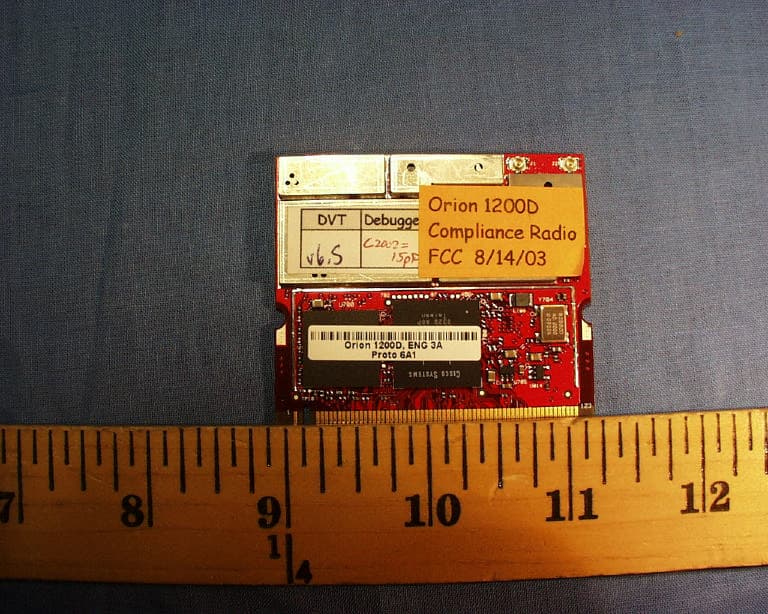
Click to zoom
Application Details
- Equipment Class
- DTS - Digital Transmission System
- Date of Grant
- Aug 10, 2004
- Application Purpose
- Original Equipment
- Date of Application
- Aug 10, 2004
- Equipment Note
- In Building RF Distribution System
- Frequency Range
- 2412.00000000 - 2462.00000000
- Country
- United States
Documents & Files
Document Text
Text extracted from the exhibit documents filed with the FCC. Open a document above to read the original.
Users Manual
UM 850, Rev 1.2 I MobileAccess™ 850 Installation and Configuration Guide UM 850, Rev 1.2 August, 2004 Introduction MobileAccess™ 850 II UM 850, Rev 1.2 Copyright © 2004 MobileAccess. © 2004 by MobileAccess This document contains confidential and proprietary information of MobileAccess and may not be copied, transmitted, stored in a retrieval system or reproduced in any format or media, in whole or in part, without the prior written consent of MobileAccess. Information contained in this document supersedes any previous manuals, guides, specifications, data sheets or other information that may have been provided or made available to the user. This document is provided for informational purposes only, and MobileAccess does not warrant or guarantee the accuracy, adequacy, quality, validity, completeness or suitability for any purpose of the information contained in this document. MobileAccess reserves the right to make updates, improvements and enhancements to this document and the products to which it relates at any time without prior notice to the user. MOBILEACCESS MAKES NO WARRANTIES, EXPRESS OR IMPLIED, INCLUDING, WITHOUT LIMITATION, THOSE OF MERCHANTABILITY AND FITNESS FOR A PARTICULAR PURPOSE, WITH RESPECT TO THIS DOCUMENT OR ANY INFORMATION CONTAINED HEREIN. TRADEMARK ACKNOWLEDGEMENT MobileAccess TM is a registered trademarks of MobileAccess. This document contains other trademarks, trade names and service marks of MobileAccess and other organizations, all of which are the property of their respective owners. MobileAccess Ltd. Vienna, Virginia Tel: +1-703-848-0200 MobileAccess Ltd. Lod, Israel Tel: +972-8-9183888 http://www.MobileAccess.com Email: [email protected] MobileAccess™ 850 Introduction UM 850, Rev 1.2 III POLICY FOR WARRANTEE AND REPAIR MobileAccess tests and inspects all its products to verify their quality and reliability. MobileAccess uses every reasonable precaution to ensure that each unit meets their declared specifications before shipment. Customers should advise their incoming inspection, assembly, and test personnel about the precautions required in handling and testing our products. Many of these precautions can be found in this manual. The products are covered by the following warranties: General Warranty MobileAccess warrants to the original purchaser all standard products sold by MobileAccess to be free of defects in material and workmanship for one (1) year from date of shipment from MobileAccess. During the warranty period, MobileAccess will repair or replace any product that MobileAccess proves to be defective. This warranty does not apply to any product that has been subject to alteration, abuse, improper installation or application, accident, electrical or environmental over-stress, negligence in use, storage, transportation or handling. Specific Product Warranty Instructions All MobileAccess products are warranted against defects in workmanship, materials and construction, and to no further extent. Any claim for repair or replacement of units found to be defective on incoming inspection by a customer must be made within 30 days of receipt of shipment, or within 30 days of discovery of a defect within the warranty period. This warranty is the only warranty made by MobileAccess and is in lieu of all other warranties, expressed or implied. MobileAccess sales agents or representatives are not authorized to make commitments on warranty returns. RETURNS In the event that it is necessary to return any product against above warranty, the following procedure shall be followed: 1. Return authorization is to be received from MobileAccess prior to returning any unit. Advise MobileAccess of the model, serial number, and discrepancy. The unit may then be forwarded to MobileAccess, transportation prepaid. Devices returned collect or without authorization may not be accepted. 2. Prior to repair, MobileAccess will advise the customer of our test results and any charges for repairing customer-caused problems or out-of-warranty conditions etc. 3. Repaired products are warranted for the balance of the original warranty period, or at least 90 days from date of shipment. Introduction MobileAccess™ 850 IV UM 850, Rev 1.2 LIMITATIONS OF LIABILITIES MobileAccess's liability on any claim, of any kind, including negligence for any loss or damage arising from, connected with, or resulting from the purchase order, contract, quotation, or from the performance or breach thereof, or from the design, manufacture, sale, delivery, installation, inspection, operation or use of any equipment covered by or furnished under this contact, shall in no case exceed the purchase price of the device which gives rise to the claim. EXCEPT AS EXPRESSLY PROVIDED HEREIN, MOBILEACCESS MAKES NO WARRANTY, EXPRESSED OR IMPLIED, WITH RESPECT TO ANY GOODS, PARTS AND SERVICES PROVIDED IN CONNECTION WITH THIS AGREEMENT INCLUDING, BUT NOT LIMITED TO, THE IMPLIED WARRANTIES OF MERCHANTABILITY AND FITNESS FOR A PARTICULAR PURPOSE. MOBILEACCESS SHALL NOT BE LIABLE FOR ANY OTHER DAMAGE INCLUDING, BUT NOT LIMITED TO, INDIRECT, SPECIAL OR CONSEQUENTIAL DAMAGES ARISING OUT OF OR IN CONNECTION WITH FURNISHING OF GOODS, PARTS AND SERVICE HEREUNDER, OR THE PERFORMANCE, USE OF, OR INABILITY TO USE THE GOODS, PARTS AND SERVICE. REPORTING DEFECTS The units were inspected before shipment and found to be free of mechanical and electrical defects. Examine the units for any damage that may have been caused in transit. If damage is discovered, file a claim with the freight carrier immediately. Notify MobileAccess as soon as possible. NOTE: Keep all packing material until you have completed the inspection WARNING: To comply with FCC RF exposure compliance requirements, antennas used for this product must be fixed mounted on indoor permanent structures, providing a separation distance of at least 20 cm from all persons during normal operation. WARNING: Antenna gain should not exceed 10dB. WARNING: Each individual antenna used fo…
Text truncated - open the document above for the full version.
Cover Letter(s)
tel: 650-726-1263 fax: 650-726-1252 [email protected] Thomas N. Cokenias EMC &Radio Approvals Test & Consulting Services for Commercial, Military, International Compliance P.O. Box 1086 El Granada, CA 94018 email: [email protected] 3 July 2004 Compliance Certification Services 561F Monterey Road Morgan Hill CA 95037 Attention; Mike Kuo Re: FCC Certification for Mobile Access Networks model MA850 FCC ID: OJFMA850 Dear Mike, The referenced device is an 802.11b/g in-building RF distribution system. Through use of triplexers, band -reject and band-pass filters, the MA-850 allows its multi-band antennas to be used with 802.11a signals at 5 GHz, as well as with SMR/LMR/Cellular PCS signals in the 800 – 1900 MHz frequency bands. These other bands are not processed by any of the 802.11b/g circuitry, they are passively coupled from other FCC certified devices to the antennas being used by the 802.11b/g signals. I do not believe this product will require certification under other rule parts because the other band signals are processed by separately certified devices. Data shows no interaction between desired 2.4 GHz signals and signals in the other operating bands. If you have questions or need further information, please don’t hesitate to call. MobileAccess Networks has asked for expedited service on this application and I see to it that you get whatever additional information you need as quickly as possible. Sincerely, Tom Cokenias Agent for MobileAccess NetworksFC
Cover Letter(s)
Cisco Systems, Inc. 4125 Highlander Parkway Richfield, Ohio 44286 Phone: 330 523-2094 Fax: 330 523-2002 http://www.cisco.com Phone: (330) 523-2094 Fax: (330) 523-2002 E-Mail: [email protected] July 19, 2004 Federal Communications Commission Equipment Authorization Division, Application Processing Branch 7435 Oakland Mills Road Columbia, MD 21046 Re: FCC ID: OJFMA850 To Whom It May Concern: The following information is to be held confidential pursuant to 47 CFR Part 0 §0.457 and Section 552(b)(4) of the Freedom of Information Act, because the information provided is proprietary and contains trade secrets. If made public, the information might be used to the disadvantage of the Cisco Systems, Inc. in the market place. AIR-MP21G-A-K9 Schematic Diagrams Best Regards, Jim Nicholson EMC Compliance Engineer
Cover Letter(s)
tel: 650-726-1263 fax: 650-726-1252 [email protected] Thomas N. Cokenias EMC &Radio Approvals Test & Consulting Services for Commercial, Military, International Compliance P.O. Box 1086 El Granada, CA 94018 email: [email protected] Compliance Certification Services 561F Monterey Road Morgan Hill, CA 95037 Attention: Mike Kuo Re: Request to withhold indefinitely portions of certification application from public view per FCC Rule Part: 0.459 Applicant: MobileAccess Networks FCC ID:OJFMA850 Dear Mike, On behalf of my client MobileAccess Networks, I request the following documents be withheld from public view for an indefinite period of time: Schematics Block diagram Theory of operation MobileAccess Networks has invested considerable resources in the design and execution of this product and as such, other manufacturers would be afforded an unfair competitive advantage were the referenced documents to be made easily available. The referenced device incorporates devices manufactured by Cisco Systems and Linksys. The schematics and block diagrams for these devices will be provided to the TCB via “ third party confidentiality request “ submissions. If you have questions or need further information, please contact the undersigned. Sincerely, THOMAS N COKENIAS Agent for MobileAccess Networks
Cover Letter(s)
Hi Mike, Attached is a description of the system and what follows is Rich Fabina email to them and summaries of discussion with FCC. I'll be in the office today if you have questions or wish to discuss. Thanks for your help with this and with the modular items Mike. best regards Tom >X-Original-To: [email protected] >Delivered-To: [email protected] >Subject: MA-850 approval process- FCC contacts >Date: Tue, 22 Jun 2004 19:39:42 +0300 >Thread-Topic: MA-850 approval process- FCC contacts >Thread-Index: AcRYBTAUSrap7ZhUSxqmkptyvITiCAAcOnpw >From: "Yair_Shapira" <[email protected]> >To: "Tom Cokenias" <[email protected]> >Cc: "Shay Simchon" <[email protected]> >X-Spam-Checker-Version: SpamAssassin 2.63-1.2 (2004-01-11) on > ethra2.cokenias.org >X-Spam-Level: >X-Spam-Status: No, hits=-4.6 required=6.5 tests=BAYES_00,HTML_60_70, > HTML_FONTCOLOR_UNKNOWN,HTML_MESSAGE autolearn=no version=2.63-1.2 >Status: RO > >Tom, > > > >Per our call earlier, following please find some references for the >discussions we had with the FCC regarding the approval of the MA850. > > > > > >Regards > > > >Yair Shapira > >VP Research and Development > >MobileAccess Ltd. > >Office : 972-8-9183888 > >Mobile: 972-53-275573 > >Email: [email protected] > >Website: <http://www.mobileaccess.com/>http:\\www.MobileAccess.com > > > > > > > > > >Summary of a meeting with FCC officers regarding the approval >procedure of the MA 850 > > > >Date: 14 May 2004 > > > >FCC Attendees: Alan Scrime: Chief Policy and Rules Division > > Rich Fabina, Chief of Equipment Auth Branch > > Rashmi Doshi, Lab Director (above RichŠnot >sure exact title) > > > >Mobile Access: Jeff Kunst VP product management > > > > > >Rich Fabina is the main person that we will need to work with on >this project will be our point of contact when the testing is >complete and ready to be submitted. > > > >Rich Fabian felt that it will be ok to leave the approval for the >type-2 system (MA-1000) alone because it is not approved with an >antenna anyway and that he only cares about the type-2 system >relative to any additional intermodulations that might be created >when combining with the type-15 (MA-850). Although he understands >that nothing occur here due to high isolation and passive nature of >the triplexer, but he wants to see the test reports showing that >this is the case. > > > >They did not seem concerned about the b/g ports being empty since >there was no way to send more than 100mw to each port and even the >total is less than the 1w allowed. > > > >Conclusions: > >- The MA-850 needs to be tested in multiple configurations >to show normal operation and worst case > >o 1,2,3,4 b/g ports operating with both 4 "a" ports blocked. > >o They would like to see a separate set of tests with the >CELLULAR/PCS ports operating so that they can see that there is no >impact on these signals as they radiate simultaneously out of the >antenna. > >- Need to submit data on the triplexer characteristics from >testing. It is important that we prove that all ports are frequency >limited with filters and that there is strong isolation between >themŠand, of course, that there is no impact on the cellular signals >that pass through. > >- Need to insure we are careful on the "a" portsŠnow we >need some kind of factory installed cover on the "a" ports. > >- The test report submitted needs to be augmented with the >cellular dataŠIt can be put in an appendix since it is not really >relevant to the type-15 testing. The Type-2 FCC IDs should be >referenced in this part of the report > >- Before we send the report in, we should notify Rich >Fabina that it is coming. We can contact him directly if we have >questions about what to test (or not to test). > > > > > > > > > > > >Later Correspondence with Rich Fabina > > > >-----Original Message----- >From: Rich Fabina [mailto:[email protected]] >Sent: Friday, June 04, 2004 1:57 PM >To: Jeff Kunst >Cc: Joe Dichoso >Subject: RE: MobileAccess Networks: Question about approval process > > > >Jeff, > > > >If you want the grant quickly, you will have to go to a TCB for >Certification. Our processing backlog indicates that we will not >review an application for Certification until 45 days after it is >received at the Lab. If we have questions on the application, they >will have to be answered before we can issue the grant of >Certification. This process can currently take in excess of 60 days. > > > >I cannot recommend one TCB over another and remain impartial. >However, I suggest you ask a prospective TCB how many applications >for this Rule Part that they have processed. Alternatively, you can >look on the database at ><http://www.fcc.gov/oet/fccid>www.fcc.gov/oet/fccid under the >equipment class or Rule Part that the application will be filed to >see who has done the most applications of this type. If I remember >correctly, this is a Part 24 device that will be filing under >equipment class PCB. > > > >The TCB you ultimately choose can certainly contact myself or Mr. >Joe Dichoso to ask questions that they may have when processing this >application. > > > >I trust that this has responded to this inquiry. > > > >Thanks, > >Rich > >-----Original Message----- >From: Jeff Kunst [mailto:[email protected]] >Sent: Tuesday, June 01, 2004 6:06 PM >To: Rich Fabina >Cc: Yair_Shapira >Subject: MobileAccess Networks: Question about approval process > >Rich, > > > >Hello. First I want to again say thanks for your time several days >ago when you met with us to consult about the testing required to >smooth out the approval process for the new MobileAccess equipment >that allows the convergence of Wi-Fi and Cellular systems indoors. >I am contacting you now to request your advice on the submission of >the test results on our converged Wi-Fi/Cellular in-building >wireless equipment. > > > >We are now entering a local lab in Israel for the required FCC >testing of the equipment and wanted to get your opinion on how to >submit the test…
Text truncated - open the document above for the full version.
Cover Letter(s)
TCB GRANT OF EQUIPMENT AUTHORIZATIONTCB Certification Issued Under the Authority of the Federal Communications Commission By: Compliance Certification Services 561F Monterey Road Morgan Hill, CA 95037 United States Date of Grant: 09/24/2003 Application Dated: 09/24/2003 Cisco Systems Inc 170 West Tasman Drive San Jose, CA 95134-1706 United States Attention: Andrew Griffin , Manager, Regulatory Compliance NOT TRANSFERABLE EQUIPMENT AUTHORIZATION is hereby issued to the named GRANTEE, and is VALID ONLY forthe equipment identified hereon for use under the Commission's Rules and Regulations listed below. FCC IDENTIFIER: LDK102049 Name of Grantee: Cisco Systems Inc Equipment Class:Digital Transmission System Notes:802.11 b/g Mini-PCI Radio Module Grant Notes FCC Rule Parts Frequency Range (MHZ) Output Watts Frequency Tolerance Emission Designator CE15C - 2412.0 2462.0 0.196 Modular approval. Output power listed is conducted. This device may only be used in Cisco Access Point with specific antennas as documented in this filing. Co-located 802.11/a optional transmitter operating conditions with FCC ID:LDK102045 have been evaluated as described in this filing - separate equipment certification is needed for other co-location configurations and RF exposure conditions.The antenna(s) used for this transmitter must be installed to provide a separation distance of at least 20 cm from all persons and must not be co-located or operating in conjunction with any other antenna or transmitter. This device must utilize a BIOS lock mechanism to allow end user installation and ensures use only with hosts as specified in the Certification filing. End- Users must be provided with transmitter operation conditions for satisfying RF exposure compliance. This device must be marketed for indoor use only when optional 802.11/a radio is installed. CE:This device has shown compliance with the conducted emissions limits in 15.107, 15.207, or 18.307 adopted under FCC 02-157 (ET Docket 98-80). The device may be marketed after July 11, 2005, and is not affected by the 15.37(j) or 18.123 transition provisions. 7/13/04 6:50 AMFCC - OET TCB Form 731 Grant of Equipment Authorization Page 1 of 1https://gullfoss2.fcc.gov/prod/oet/cf/tcb/reports/Tcb731GrantForm.cfm?mode=COPY&RequestTimeout=500&application_id=866930&fcc_id=LDK102049
External Photos
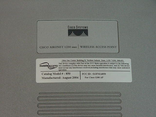
MA850 photos MA850 top view: FCC Label area MA850 back panel with cover for the 802.11a AP’s
Internal Photos
MA850 internal view with shield MA850 internal view without shield
Parts List/Tune Up Info
ÆìStripes of Qualityî 15 www.antenna.com Specifications Electrical Power Rating50 watts GainUnity (0 dBd, 2 dBi) Frequency Range806-960 MHz; 1710-3000 MHz VSWR2:1 Input Impedance50 ohms PolarizationVertical E-plane Beamwidth90∞ typical H-plane BeamwidthOmnidirectional Mechanical Radome Diameter8.1 inches (205 mm) Radome Depth2.6 inches (67 mm) Radome MaterialABS RadiatorBrass Weight0.7 pounds (0.3 kg) MountingSolid or hollow, fixed ceiling Mounting Hardware3 wall anchors, #8 x 1 inch long Phillips and screw covers, 3/16 inch (5 mm) drill size needed ConnectorN female bulkhead CableAvailable separately Fixed Station Multiband Indoor Antenna Model ASP-3561 Versatile ó combines trunking, cellular, GSM, ISM, DCS1800 and PCS1900 frequencies into one indoor antenna Economical ó provides a cost-effective solution for high volume deployments and multiple in-building systems Precision Engineered ó incorporates capacitive fed, broad band microstrip circuitry Unobtrusive ó low profile blends easily with internal environment for unobtrusive appearance DC Grounded ó to meet local electrical building codes Convenient ó simple to install for indoor ceiling mount applications TRUNKING FIXED STATION ANTENNAS 8.1 inches (205 mm) 2.6 inches (67 mm)
Parts List/Tune Up Info
www.rfsworld.com Americas +1 203 630 3311 / Mercosur +55 11 7961 2433 / Europe, Mid East, Africa +49 511 676 2520 / North Asia +86 21 5774 4500 / South Asia +61 3 9751 8400 Product Data Sheet for AO8818DC00-28T0 MicroTenna™ Indoor Antenna The Celwave® MicroTenna series is the ideal choice for all indoor antenna requirements. When your planning indoor ESMR, AMPS, GSM, DCS or PCS systems the Celwave® MicroTenna series has an antenna that can make your installation quick and easy. Each MicroTenna series antenna uses our ingenious wall/ceiling mount for mounting on various surfaces. Their off-white color radome blends easily into most building aesthetics. The integrated connector keeps the diameter of the cable connector small. The MicroTenna series offers has a dual-band model that covers all wireless services from 806 to 2700 MHz. The MicroTenna series is available with various patterns and gains form unity to 6 dB. Product Specifications Frequency BandTrunking/SMR (806-824, 851-869 MHz), Cellular (824-849, 869-894 MHz), GSM 900/ETACS (872-915, 917-960 MHz), GSM 1800 (1710-1785, 1805-1880 MHz), PCS 1900 (1850-1990 MHz) Horizontal PatternOmnidirectional Antenna TypeIndoor Electrical Down Tilt OptionFixed Gain, dBi (dBd)2.14 (0) Frequency Range, MHz806-2700 Connector TypeN Female Connector LocationBottom Mount TypeFixed Electrical Downtilt, deg0 Horizontal Beamwidth, deg360 Mounting HardwareUniversal Wall & Ceiling Mount Gain (Omni), dBi (dBd)2.14 (0) VSWR< 1.5:1 Vertical Beamwidth, deg66 PolarizationVertical Maximum Power Input, W50 Lightning protection(N/A) Indoor Product www.rfsworld.com Americas +1 203 630 3311 / Mercosur +55 11 7961 2433 / Europe, Mid East, Africa +49 511 676 2520 / North Asia +86 21 5774 4500 / South Asia +61 3 9751 8400 Product Data Sheet for AO8818DC00-28T0 (Cont.) MicroTenna™ Indoor Antenna Dimensions - HxWxD, mm (in)152 x 102 x 102 (6 x 4 x 4) Weight w/o Mtg. Hardware, kg (lb)Hdwr Included Weight w/ Mtg. Hardware, kg (lb)3.8 (1.5) Radiating Element MaterialBrass Radome MaterialABS Reflector MaterialAluminum Max Wind Loading Area, m² (ft²)N/A (Indoor Application) Shipping Weight, kg (lb)0.9 (2) Shipping Dimensions of Accessory - HxWxD, m (ft) Packed w/ Antenna Shipping ModeUPS Packing Dimensions, HxWxD, mm (in)305 x 305 x 229 (12 x 12 x 9) Features/Benefits • Small size – aesthetically pleasing for indoor installations. • Integrated Ceiling/Wall Mount for easy installation. • Various patterns available to efficiently cover target area. • Broadband model available – covers SMR, cellular, DCS and PCS with one Antenna. Note Application = Indoor, ceiling Pattern = Omni, Vertical pol. with null below antenna Key = Single Monopole
Parts List/Tune Up Info
MULTIBAND OMNI MA-CM36-15 Multi Band Omni Antenna MA-CM36-15 Mars Multi Band Omni Antenna covers GSM/AMPS/IDEN/PCS/UMTS/WLAN/BLUETOOTH bands. The antenna is aesthetic, small and has unobtrusive profile that blends easily with any environment. Specifications: Electrical Standard SMR, AMPS, CDMA, TDMA, GSM 900 PCS, DECT, GSM 1900, UMTS Bluetooth , ISM WLAN Frequency, MHz 806-960 1710 – 2170 2400 – 2500 Gain, typ. 2 dBi 3 – 4 dBi 5 dBi VSWR, max. 2.0: 1 1.5: 1 1.8: 1 Polarization Linear Vertical Power 50 W Impedance 50 Ohms Mechanical and Environmental Dimensions Base Diameter-205 mm, Height-89 mm Connector N-Type, Female RadomeABS, UV Protected Temperature-40°C to +70°C Base plate Aluminum Environmental Indoor Usage (Outdoor version available on request) Specifications subject to change without notice Patent Pending MULTIBAND OMNI MA-CM36-15
Parts List/Tune Up Info
Engineering Data Sheet Part #: AIR-ANT1728 (Ceiling Mount) Part #: AIR-ANT3213 (Mast Mount) 5 dBi, Diversity Omni-directional Specifications: Frequency Range........................2.5 GHz VSWR............................................<2:1 Nominal Impedance...................50 ohms Gain..............................................5 dBi Nominal Coax..............................................6” Dual 50 Ohm Low LossRG58 Coax Termination......................TNC Reverse Polarity Plug Elevation Pattern Engineering Data Sheet Part #: AIR-ANT1729 6 dBi, Patch Antenna Specifications: Frequency Range.......................2.4 - 2.5 GHz VSWR............................................1.5:1 Gain..............................................6 dBi Front to back Ratio...................18dB Termination.................................Rev. TNC and RG-58 Height...........................................0.525” Width.............................................3.806” Length...........................................5.181” Material.......................................ABS Plastic E plane and H plane Engineering Data Sheet Part #: AIR-ANT2012 2.4 GHz Spatial Diversity Directional Antenna Specifications: Frequency Range.......................2.4-2.5 GHz VSWR............................................1.7:1 Nominal Impedance...................50 ohms Gain..............................................6.5 dBi Nominal Polarization................................Vertical Linear Coax..............................................Dual Low Loss RG58 Coax Termination......................TNC Rev. Pol. Plug Weight...........................................9.6oz Power............................................10 Watts Length ..........................................6-21/32’ Engineering Data Sheet Part #: AIR-ANT2506 3 dBd, Omni-directional Antenna Specifications: Frequency Range.......................2.4 –2.5 GHz VSWR............................................1.5:1 Nominal Impedance...................50 ohms Gain..............................................3 dBd Nominal E-Plane 3dB Beamwidth...........38 Degrees Max Power...................................50 Watts Material.......................................Polycarbonate Package.......................................Outdoor Coax..............................................36” RG58 Coax Termination......................TNC Rev. Pol. Plug Engineering Data Sheet Part #: AIR-ANT3213 5 dBi, Diversity Omni-directional Specifications: Frequency Range........................2.5 GHz VSWR............................................<2:1 Nominal Impedance...................50 ohms Gain..............................................5 dBi Nominal Coax..............................................6” Dual 50 Ohm Low LossRG58 Coax Termination......................TNC Reverse Polarity Plug Elevation Pattern Engineering Data Sheet Part #: AIR-ANT3351 Omni-directional Antenna Assembly, Positive Diversity Specifications: Frequency Range.......................2.4-2.5 GHz VSWR............................................1.5:1 Power............................................10-Watt Max Gain..............................................3.5 dBi Elev. Plane 3 dB B.W.................45 Degrees (Peak at 53) Polarization................................Vertical Linear Termination.................................Reverse TNC 36” of RG-58 Weight............................................4.8 oz Engineering Data Sheet Part #: AIR-ANT3549 8.5 dBi, Patch Antenna Specifications: Frequency Range.......................2.4 –2.5 GHz VSWR............................................1.5:1 Nominal Impedance ..................50 ohms Gain .............................................8.5 dBi Nominal E-Plane 3dB Beamwidth...........55 Degrees H-Plane 3dB Beamwidth...........60 Degrees Polarization ...............................Linear Coax. ............................................36” RG-58 Coax Termination .....................TNC Rev. Pol. Environment................................Indoors/Outdoors Engineering Data Sheet Part #: AIR-ANT4941 2.2 dBi, Low Profile Dipole Antenna Specifications: Frequency Range.......................2.45-2.4835 GHz VSWR............................................1.5:1 Nominal Impedance...................50 ohms Gain..............................................2.2 dBi Nominal Polarization................................Vertical Termination.................................TNC Rev. Pol. Plug Engineering Data Sheet Part #: AIR-ANT5959 2.4 GHz, 2dBi Integrated Omnidirectional Diversity Antennas Specifications: Frequency Range.......................2.4 - 2.5 GHz VSWR............................................1.7:1 Power............................................5 Watts Gain..............................................2 dBi Polarization ...............................Vertical Linear Azimuth Pane Beamwidth.........Omni Directional Elevation Plane 3dB BW...........80 Degrees Antenna Connector....................Reverse TNC (2X) H-Plane E-Plane -30 -20 -10 0 10 0 20 40 60 80 100 120 140 160 180 -160 -140 -120 -100 -80 -60 -40 -20 Telex Communications, INC. 8601 E. Cornhusker Hwy Lincoln, NE 68507 Phone: (402) 467-5321 Fax: (402) 467-3279 2409AB Yagi AZIMUTH Pattern Frequency List Freq: 2.400 GHz Freq: 2.441 GHz Freq: 2.483 GHz -30 -20 -10 0 10 0 20 40 60 80 100 120 140 160 180 -160 -140 -120 -100 -80 -60 -40 -20 Telex Communications, INC. 8601 E. Cornhusker Hwy Lincoln, NE 68507 Phone: (402) 467-5321 Fax: (402) 467-3279 2409AB Yagi ELEVATION Pattern Frequency List Freq: 2.400 GHz Freq: 2.441 GHz Freq: 2.483 GHz
Test Report
MA850 part 15 tests MA850 peak output power..............................................................................................2 MA850 peak output power connected to MA1000 with cell800 frequencies operation........................16 MA850 peak output power connected to MA1000 with PCS1900 frequencies operation.....................37 MA850 6 dB bandwidth and 99% power bandwidth...............................................................51 MA850 6 dB bandwidth and 99% power bandwidth connected to MA1000 with cell800 operation........73 MA850 6 dB bandwidth and 99% power bandwidth connected to MA1000 with PCS1900 operation.....87 1.1 Peak output power Figure 1.1.1 Peak output power test setup EUTAttenuator Spectrum analyzer Photograph 1.1.1 Peak output power test setup Table 1.1.1 Peak output power test results ASSIGNED FREQUENCY: 2401 - 2473 MHz ASSEMBLY MA 850 TRANSMITTER OUTPUT POWER SETTINGS: Maximum DETECTOR USED: Peak CHANNEL POWER BANDWIDTH 50 MHz RESOLUTION BANDWIDTH: 100 kHz VIDEO BANDWIDTH: 300 kHz Carrier frequency, MHz Modulating signal Bit rate, Mbps Port Peak output power, dBmLimit, dBm Margin*, dB Verdict DSSS 2412 26.0 30 -4.0 Pass 2437 26.3 30 -3.7 Pass 2462 CCK 5.5 2 25.8 30 -4.2 Pass OFDM 2412 20.1 30 -9.9 Pass 2437 20.2 30 -9.8 Pass 2462 BPSK 6 2 20.1 30 -9.9 Pass * - Margin = Peak output power – specification limit. Reference numbers of test equipment used HL 1424 HL 1651 HL 2399 Full description is given in Appendix A. Plot 1.1.1 Pea…
Text truncated - open the document above for the full version.
Contact Information
Applicant
Dana Whitney(Director of Operations and Program)
Test Firm
Standard Institution of IsraelSteli Loznen
Technical Specifications
| # | Rule Parts | Frequency Range | Power Output |
|---|---|---|---|
| 1 | 15C | 2.41 GHz - 2.46 GHz | 457.00 mW |
Other Applications from Corning Optical Communication LLC

OJFE62-N3-7US
Aug 29, 2024Remote Unit, Radio Node
Equipment Class
B2I - Part 20 Industrial Booster (CMRS)
OJFDHRU-G2-19
Apr 09, 2024HRU Digital High Power Amplifier Module supporting PCS
Equipment Class
B2I - Part 20 Industrial Booster (CMRS)
OJFDLRUG2678
Oct 17, 2023Low Band dRAU
Equipment Class
B2I - Part 20 Industrial Booster (CMRS)
OJFDMRUG22325
Jul 31, 2023digital Medium-power Remote Unit
Equipment Class
B2I - Part 20 Industrial Booster (CMRS)
OJFDMRUG2678
Jul 30, 2023digital Medium-power Remote Unit
Equipment Class
B2I - Part 20 Industrial Booster (CMRS)