OJFMA850A1In Building RF Distribution System
Corning Optical Communication LLC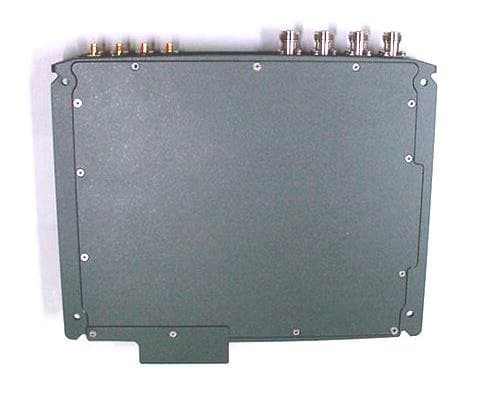
Click to zoom
Application Details
- Equipment Class
- NII - Unlicensed National Information Infrastructure TX
- Date of Grant
- Jul 18, 2006
- Application Purpose
- Original Equipment
- Date of Application
- Jul 18, 2006
- Equipment Note
- In Building RF Distribution System
- Frequency Range
- 5745.00000000 - 5805.00000000
- Country
- United States
Documents & Files
Document Text
Text extracted from the exhibit documents filed with the FCC. Open a document above to read the original.
Users Manual
P/N: 709C00110x REV: 1.1 Date: July 2006 M M M o o o b b b i i i l l l e e e A A A c c c c c c e e e s s s s s s 8 8 8 5 5 5 0 0 0 A A A 1 1 1 Installation and Configuration Guide Preface Preface Material MA 850A1A1 Installation and Configuration Guide II MobileAccess Ltd. Vienna, Virginia Tel: +1-703-848-0200 MobileAccess Ltd. Lod, Israel Tel: +972-8-9183888 http://www.MobileAccess.com Preface Preface Material MA 850A1A1 Installation and Configuration Guide III P P r r e e f f a a c c e e M M a a t t e e r r i i a a l l © COPYRIGHT 2006, MOBILEACCESS NETWORKS INC. ALL RIGHTS RESERVED. M OBILEACCESSTM IS A REGISTERED TRADEMARK OF MOBILEACCESS. THIS DOCUMENT CONTAINS OTHER TRADEMARKS, TRADE NAMES AND SERVICE MARKS OF MOBILEACCESS AND OTHER ORGANIZATIONS, ALL OF WHICH ARE THE PROPERTY OF THEIR RESPECTIVE OWNERS. T HIS DOCUMENT CONTAINS CONFIDENTIAL AND PROPRIETARY INFORMATION OF MOBILEACCESS AND MAY NOT BE COPIED, TRANSMITTED, STORED IN A RETRIEVAL SYSTEM OR REPRODUCED IN ANY FORMAT OR MEDIA , IN WHOLE OR IN PART, WITHOUT THE PRIOR WRITTEN CONSENT OF MOBILEACCESS. INFORMATION CONTAINED IN THIS DOCUMENT SUPERSEDES ANY PREVIOUS MANUALS, GUIDES, SPECIFICATIONS, DATA SHEETS OR OTHER INFORMATION THAT MAY HAVE BEEN PROVIDED OR MADE AVAILABLE TO THE USER . T HIS DOCUMENT IS PROVIDED FOR INFORMATIONAL PURPOSES ONLY, AND MOBILEACCESS DOES NOT WARRANT OR GUARANTEE THE ACCURACY, ADEQUACY , QUALITY, VALIDITY, COMPLETENESS OR SUITABILITY FOR ANY PURPOSE OF THE INFORMATION CONTAINED IN THIS DOCUMENT. MOBILEACCESS RESERVES THE RIGHT TO MAKE UPDATES, IMPROVEMENTS AND ENHANCEMENTS TO THIS DOCUMENT AND THE PRODUCTS TO WHICH IT RELATES AT ANY TIME WITHOUT PRIOR NOTICE TO THE USER . MOBILEACCESS MAKES NO WARRANTIES, EXPRESS OR IMPLIED, INCLUDING, WITHOUT LIMITATION, THOSE OF MERCHANTABILITY AND FITNESS FOR A PARTICULAR PURPOSE, WITH RESPECT TO THIS DOCUMENT OR ANY INFORMATION CONTAINED HEREIN. Preface Preface Material MA 850A1A1 Installation and Configuration Guide IV Policy for Warrantee and Repair MOBILEACCESS TESTS AND INSPECTS ALL ITS PRODUCTS TO VERIFY THEIR QUALITY AND RELIABILITY. MOBILEACCESS USES EVERY REASONABLE PRECAUTION TO ENSURE THAT EACH UNIT MEETS THEIR DECLARED SPECIFICATIONS BEFORE SHIPMENT . CUSTOMERS SHOULD ADVISE THEIR INCOMING INSPECTION , ASSEMBLY, AND TEST PERSONNEL ABOUT THE PRECAUTIONS REQUIRED IN HANDLING AND TESTING OUR PRODUCTS. MANY OF THESE PRECAUTIONS CAN BE FOUND IN THIS MANUAL . T HE PRODUCTS ARE COVERED BY THE FOLLOWING WARRANTIES: General Warranty MOBILEACCESS WARRANTS TO THE ORIGINAL PURCHASER ALL STANDARD PRODUCTS SOLD BY MOBILEACCESS TO BE FREE OF DEFECTS IN MATERIAL AND WORKMANSHIP FOR ONE (1) YEAR FROM DATE OF SHIPMENT FROM MOBILEACCESS. DURING THE WARRANTY PERIOD, MOBILEACCESS WILL REPAIR OR REPLACE ANY PRODUCT THAT MOBILEACCESS PROVES TO BE DEFECTIVE. THIS WARRANTY DOES NOT APPLY TO ANY PRODUCT THAT HAS BEEN SUBJECT TO ALTERATION , ABUSE, IMPROPER INSTALLATION OR APPLICATION, ACCIDENT, ELECTRICAL OR ENVIRONMENTAL OVER -STRESS, NEGLIGENCE IN USE, STORAGE, TRANSPORTATION OR HANDLING. Specific Product Warranty Instructions ALL MOBILEACCESS PRODUCTS ARE WARRANTED AGAINST DEFECTS IN WORKMANSHIP, MATERIALS AND CONSTRUCTION, AND TO NO FURTHER EXTENT . ANY CLAIM FOR REPAIR OR REPLACEMENT OF UNITS FOUND TO BE DEFECTIVE ON INCOMING INSPECTION BY A CUSTOMER MUST BE MADE WITHIN 30 DAYS OF RECEIPT OF SHIPMENT, OR WITHIN 30 DAYS OF DISCOVERY OF A DEFECT WITHIN THE WARRANTY PERIOD. THIS WARRANTY IS THE ONLY WARRANTY MADE BY MOBILEACCESS AND IS IN LIEU OF ALL OTHER WARRANTIES, EXPRESSED OR IMPLIED. MOBILEACCESS SALES AGENTS OR REPRESENTATIVES ARE NOT AUTHORIZED TO MAKE COMMITMENTS ON WARRANTY RETURNS. Returns IN THE EVENT THAT IT IS NECESSARY TO RETURN ANY PRODUCT AGAINST ABOVE WARRANTY, THE FOLLOWING PROCEDURE SHALL BE FOLLOWED: 1. RETURN AUTHORIZATION IS TO BE RECEIVED FROM MOBILEACCESS PRIOR TO RETURNING ANY UNIT. ADVISE MOBILEACCESS OF THE MODEL, SERIAL NUMBER , AND DISCREPANCY. THE UNIT MAY THEN BE FORWARDED TO MOBILEACCESS, TRANSPORTATION PREPAID. DEVICES RETURNED COLLECT OR WITHOUT AUTHORIZATION MAY NOT BE ACCEPTED . 2. PRIOR TO REPAIR, MOBILEACCESS WILL ADVISE THE CUSTOMER OF OUR TEST RESULTS AND ANY CHARGES FOR REPAIRING CUSTOMER-CAUSED PROBLEMS OR OUT -OF-WARRANTY CONDITIONS ETC. 3. REPAIRED PRODUCTS ARE WARRANTED FOR THE BALANCE OF THE ORIGINAL WARRANTY PERIOD, OR AT LEAST 90 DAYS FROM DATE OF SHIPMENT . Limitations of Liabilities MOBILEACCESS'S LIABILITY ON ANY CLAIM, OF ANY KIND, INCLUDING NEGLIGENCE FOR ANY LOSS OR DAMAGE ARISING FROM, CONNECTED WITH, OR RESULTING FROM THE PURCHASE ORDER , CONTRACT, QUOTATION, OR FROM THE PERFORMANCE OR BREACH THEREOF, OR FROM THE DESIGN, MANUFACTURE , SALE, DELIVERY, INSTALLATION, INSPECTION, OPERATION OR USE OF ANY EQUIPMENT COVERED BY OR FURNISHED UNDER THIS CONTACT , SHALL IN NO CASE EXCEED THE PURCHASE PRICE OF THE DEVICE WHICH GIVES RISE TO THE CLAIM. EXCEPT AS EXPRESSLY PROVIDED HEREIN, MOBILEACCESS MAKES NO WARRANTY, EXPRESSED OR IMPLIED, WITH RESPECT TO ANY GOODS, PARTS AND SERVICES PROVIDED IN CONNECTION WITH THIS AGREEMENT INCLUDING, BUT NOT LIMITED TO, THE IMPLIED WARRANTIES OF MERCHANTABILITY AND FITNESS FOR A PARTICULAR PURPOSE. MOBILEACCESS SHALL NOT BE LIABLE FOR ANY OTHER DAMAGE INCLUDING, BUT NOT LIMITED TO, INDIRECT, SPECIAL OR CONSEQUENTIAL DAMAGES ARISING OUT OF OR IN CONNECTION WITH FURNISHING OF GOODS, PARTS AND SERVICE HEREUNDER, OR THE PERFORMANCE, USE OF, OR INABILITY TO USE THE GOODS, PARTS AND SERVICE. Preface Preface Material MA 850A1A1 Installation and Configuration Guide V Reporting Defects THE UNITS WERE INSPECTED BEFORE SHIPMENT AND FOUND TO BE FREE OF MECHANICAL AND ELECTRICAL DEFECTS. E XAMINE THE UNITS FOR ANY DAMAGE THAT MAY HAVE BEEN CAUSED IN TRANSIT. IF DAMAGE IS DISCOVERED, FILE A CLAIM WITH THE FREIGHT CARRIER IMMEDIATELY . NOTIFY MOBILEACCESS AS SOON AS POSSIBLE. NOTE: KEEP ALL PACKING MATERIAL UNTIL YOU HAVE COMPLETED THE INSPECTION WARNING: TO COMPLY WITH FCC RF EXPOSURE COMPLIANCE REQUIREME…
Text truncated - open the document above for the full version.
Cover Letter(s)
Ofek One Center Building 2, Northern Industrial Zone, Lod 71293, Israel Tel: +972 8918 3897, Fax: +972 8918 3844, www.mobileaccess.com July 17, 2006 American TCB 6731 Whittier Ave Suite C110 McLean, VA 22101 USA Subject: Request for confidentiality for the RF distribution amplifier, model MA850, FCC ID:OJFMA850A1 Dear Gentlemen, In regards the exhibits submitted in support of the application for FCC ID:OJFMA850A1, please classify the following as confidential under the provision of 47 CFR 0.459: 1) Schematic diagram, file “Schematic_diagram_17138” (11 pages) 2) MA850_Block_Diagram_17138 (1 page). The above material contains trade secrets or technical data which Mobile Access Networks Ltd.. deems to be proprietary. Therefore this information would customarily be guarded from competitors and cannot be accessible to the general public. Sincerely, Kochav Yadid Director, Product Implementation & Testing
Cover Letter(s)
American Telecommunications Certification Body Inc. 6731 Whittier Ave, McLean, VA 22101 July 18, 2006 RE: Mobile Access Networks FCC ID: OJFMA850A1 After a review of the submitted information, I have a few comments on the above referenced Application. 1) Each application must stand on its own and therefore the Photographs underneath the subshields of the AP must be provided. Please provide. 2) Please explain why the operational description for the 850 mentions a maximum output of 100mW, but the 731 form and test report shows 29.7 dBm. Was a sufficient bandpass filter used to avoid overloading the analyzer. 3) The maximum allowed output for omnidirectional applications is 36 dBm. This is exceeded with 29.7 dBm and 7 dBi gain antenna. 4) RF exposure assumes the same limits for all 4 bands of operation. This is not totally correct. Additionally above there may be a concern with power issues. Please adjust RF exposure to show compliance with the distance cited. Note that the Density/Limit % of each band must add to be < 100%. Please correct/adjust as necessary. 5) RF exposure should be corrected from any power concern raised above. 6) Calculated RF exposure distance appears to be 20.5 cm, while manual only shows 20 cm (page 5). Users manual should be adjusted to match final RF exposure information. 7) Users manual section 2.4.1 should clarify model number 850 for the 802.11b/g vs. 850A or 850A1. Otherwise complete original data should be provided and also information regarding the different antennas showing they are of the same types as mentioned in the users manual. Note current testing appears to be a different type of antenna than the original and therefore not covered by the current testing. 8) Is the manual section 2.5 list the correct FCC ID for the original access point? 9) FYI... Please note that labels must be placed on the access points themselves and the previous FCC ID’s on them should be covered or removed. 10) FYI...Proper testing for the 26 dB test for the UNII portion of the device should be done 26 dB from the peak emission measured on the same plot, not the power used as a reference level. Note that this result affects the limit applied for power. However since the more stringent level is used/applied, retesting is not necessary. However for any future tests or additional testing of this device should be performed properly. 11) Please explain compliance to 15.407(c). 12) Section 7.16.2 of the UNII should factor the limit for the worse case antenna gain. For instance -27 dBm – 7 dBi = -34 dBm/MHz EIRP. Please correct. z Page 2 July 19, 2006 Timothy R. Johnson Examining Engineer mailto: [email protected] The items indicated above must be submitted before processing can continue on the above referenced application. Failure to provide the requested information may result in application termination. Correspondence should be considered part of the permanent submission and may be viewed from the Internet after a Grant of Equipment Authorization is issued. Please do not respond to this correspondence using the email reply button. In order for your response to be processed expeditiously, you must submit your documents through the AmericanTCB.com website. Also, please note that partial responses increase processing time and should not be submitted. Any questions about the content of this correspondence should be directed to the sender.
Cover Letter(s)
HERM O N LA BO RA TO RIES July 19, 2006 American TCB 6731 Whittier Ave Suite C110 McLean, VA 22101 Attn: Mr. T. Johnson, Examining Engineer RE: your e-mail dated July 18, 2006; Mobile Access Networks Ltd. FCC ID:OJFMA850A1, ATCB003764 Dear Mr. Johnson, Please find below the answers to your questions. 1) The internal photos of AP underneath the subshields, file “Internal_photos_AP-PCB_17138” was uploaded on July 19, 2006. 2) The Peak output power test was repeated with 2-4 GHz bandpass filter. The maximum measured power was 26.5 dBm (447 mW). The corrected “Operational_description_17138_rev1”, “ATCB_Form_731_17138_rev1” were uploaded on July 19, 2006. 3) The revised test report “MOBRAD_FCC.17138_rev1_part1/part2” with corrected Table 7.2.2 was uploaded on July 19, 2006. 4) The corrected file “RF_exposure_evaluation_17138_rev1” was uploaded on July 19, 2006. 5) As above 6) As above 7) The corrected User_manual_17138_rev1 was uploaded on July 19, 2006. 8) Yes, the FCC ID is correct, FCC ID:LDK102056 9) Mobile Access confirms that the labels will be placed on the access points themselves and the previous FCC ID's on them will be removed. The file “Cover letter for new labeling_17138” was uploaded on July 19, 2006 via Cover Letter folder. 10) OK, thank you. HERM O N LA BO RA TO RIES 11) MA850A1 is an amplifier and does not transmit any signal in the absence of the input signal beyond the internal noise which complies with spurious emission limits as provided in the test report. The sources of RF signal are 4 FCC approved access points (FCC ID:LDK102056). Assuming the access points were approved according to the same part of the FCC rules, the whole system complies as well. 12) The Table 7.16.2 was corrected. The revised test report “MOBRAD_FCC.17138_407_rev1_part1/part2” was uploaded on July 19, 2006. Sincerely, Marina Cherniavsky, certification engineer Hermon Laboratories
Cover Letter(s)
Page 1 of 5 Summary, Conclusions, and Final Proposals Regarding Mobile Access Networks Model 850A From Meeting March 8, 2006 Attendees: FCC – Rashmi Doshi, Joe Dichoso Mobile Access – Steve Blum ATCB – Tim Johnson Intro: Several Items were not apparent regarding approval of this device and were discussed during the meeting. 1. First is that the device itself will only receive licensed services from previously approved devices/systems. 2. All 802.11 b/g and 802.11a inputs are also from previously approved devices. 3. Only the 802.11b chain is amplified. 4. The licensed services and 802.11a services are only PASSIVELY coupled via a triplexer with the amplified 802.11b devices. Furthermore, the triplexer provides 40 dB of isolation between each service 5. The system is only professionally installed. 6. The system will always contain the 4 b/g/a access points per documentation with all b/g ports connected. Much of this was only solidified in the final part of the meeting with Joe Dichoso (Rashmi Doshi was only present for the first ½ of the meeting). Items discussed/confirmations: Confirmation A: Whether composite powers are necessary to consider for the 802.11b and various 802.11a bands? The FCC stated that as long as information is present in the application to show that the various 802.11b and 802.11a signals are not coordinated, that composite power does not apply. FCC Comments: The device is a composite device consisting of multiple transmitters with absolutely no coordination between the transmitters either by design or installation(e.g. channel selection). *At the meeting, the installation did not involve mix and matching access points and only one FCC identifier was acceptable because 4 identical access points were to always be used. However, the submitted installation instruction indicates that two access points(two fcc identifiers) are chosen and there is no limitation on the number of each that can be used. Multiple FCC identifiers will be required for each configuration. The installation guide must be consistent with what is filed for. Confirmation B: The FCC will allow labeling of the 850A instead of the access point. The new ID effectively replaces any FCC ID’s on the access points. Ideally the FCC ID’s on the access points should be covered/removed/or marked through. Page 2 of 5 FCC Comments: Section 15.19(a)4 requires the ID to go on the main unit. For transmitter/amp approvals, we have been requiring the FCC Identifier to go on the transmitter not the amp. The FCC identifier of the access points should be covered up(not scratched off) with the new label. It is ok to place another label on the amplifier as well. Page 3 of 5 Confirmation C: Populating 802.11a inputs. Given the same access point contains both 802.11 g/b and a functionality, and the fact that the 802.11 a inputs are strictly passive connections through a triplexer and there is no depopulation of access points, the FCC stated that 802.11a connections are not fully necessary to be connected since this is only lack of a particular jumper cable from the access point to the 850A. FCC Comments: Confirmed. Confirmation D: During conversations, the FCC felt it would be acceptable that MobileAccess verify through testing (at the full power expected) that additional licensed services are not affected and do not affect the 802.11b/g and 802.11 a results. Should these results be found to be worse than previous results, then a Class II PC application will be utilized as appropriate. FCC Comments: You should test with a representative sample of licensed services signals. Confirmation E: Testing Requirements Expected by FCC. Licensed Services in Radiated tests are injected using an equivalent CW signal at what is considered maximum output power. 1) 802.11 b/g only tests. Complete compliance to all 15.247 rules should be shown for all applicable tests for just the 802.11 b/g operating at maximum configuration (4 x 802.11 b/g). This includes appropriate antenna conducted output tests and radiated tests as necessary. 2) 802.11a. It is assumed that all 802.11 b/g ports will always be connected per previous comments cited above. Therefore complete compliance to all 15.407 rules may be shown for all applicable tests for 15.407 operating at maximum configuration (4 x 802.11 a + 4 x 802.11b/g inputs attached). This includes appropriate antenna conducted output tests and radiated tests as necessary for compliance to 15.407. However depending on radiated results shown in 4) below, compliance for radiated portion may be able to be shown in a single combined test with licensed services therefore making separate 802.11a testing unnecessary. 3) Comparison of 802.11b/g signals (power and bandwidth) with and without licensed services as original required by Rich Fabina in the original 850 application. Note that Rich Fabina determined for the original application that the licensed services need not be tested by themselves due to the passive coupling and nature of being previously approved without an antenna: Page 4 of 5 It is assumed that this comparison is only necessary for the 802.11b/g due to the amplifier and switching matrix present in the 850A. 802.11a signals are only passively coupled and not deemed necessary. 4) Complete system, 802.11 b/g + 802.11a + licensed tests. Radiated data showing spurious emissions compliance to licensed limit (i.e. 43+10 log = -13 dBm) or possibly meeting spurious 15.407 limits. If compliance of all spurious can be shown to meet 15.407 limits in this configuration, it is proposed that separate testing of spurious radiated for 2) above is deemed not necessary. 5) Antenna Conducted Tests – When multiple transmitters share the same antenna, the FCC requires additional antenna conducted data. The following tests are anticipated to be required: a) Simultaneous TX of 802.11b/g + a. Antenna conducted tests to show compliance to - 17/-27 dBm/MHz EIRP requirements (without licensed services operating). Limits are ap…
Text truncated - open the document above for the full version.
External Photos
Mobile Access Networks Ltd. FCC ID:OJFMA850A1 Date: July 2006 Page 1 of 4 EXTERNAL PHOTOGRAPHS This document contains 3 photographs Mobile Access Networks Ltd. FCC ID:OJFMA850A Date: November 2005 Page 2 of 4 Photograph No.1 General view Mobile Access Networks Ltd. FCC ID:OJFMA850A Date: November 2005 Page 3 of 4 Photograph No.2 Bottom view Mobile Access Networks Ltd. FCC ID:OJFMA850A Date: November 2005 Page 4 of 4 Photograph No.3 Rear panel view
External Photos
Mobile Access Networks Ltd. FCC ID:OJFMA850A1 Date: July 2006 External_photos_17138_AP.doc Page 1 of 5 EXTERNAL PHOTOGRAPHS of ACCESS POINT This document contains 4 photographs Mobile Access Networks Ltd. FCC ID:OJFMA850A1 Date: July 2006 External_photos_17138_AP.doc Page 2 of 5 Photograph No.1 Top view Mobile Access Networks Ltd. FCC ID:OJFMA850A1 Date: July 2006 External_photos_17138_AP.doc Page 3 of 5 Photograph No.2 Bottom view Mobile Access Networks Ltd. FCC ID:OJFMA850A1 Date: July 2006 External_photos_17138_AP.doc Page 4 of 5 Photograph No.3 Panel view Mobile Access Networks Ltd. FCC ID:OJFMA850A1 Date: July 2006 External_photos_17138_AP.doc Page 5 of 5 Photograph No.4 Second panel view
ID Label/Location Info
17/07/2006 MA850a1 FCC – Labeling decleration Created by Ron Hagage Page 1 of 1 To whom it may concern According to ATCB request, the updated labels for MA850A1 and AP will replace the existing labels in case of use with correlate system components (MA850A1 unit and Cisco 1242 Access Point device) Ron Hagage
ID Label/Location Info
Mobile Access Networks Ltd. FCC ID:OJFMA850A1 Date: July 2006 Label_ AP_CISCO_17138.doc Page 1 of 2 LABEL The label shown below is affixed on the bottom of the Access Point unit. The label material is PVC with a permanent adhesive. Label location on the AP bottom, FCC ID:OJFMA850A1 OfekOneCenterBuildingB,LOD71293,ISRAEL Manufactured: CatalogModel:850A Month-Year 2)Thisdevicemustacceptanyinterferencereceived, ThisdevicecomplieswithPartoftheFCCRules. Operationissubjecttothefollowingtwoconditions: 1)Thisdevicemaynotcauseharmfulinterference,and includinginterferencethatmaycauseundesiredoperation. ForCisco1242AP FCCID:OJFMA850A1
ID Label/Location Info
Mobile Access Networks Ltd. FCC ID:OJFMA850A1 Date: July 2006 Page 1 of 2 LABEL The label shown below is affixed on the bottom of the MA850 unit. The label material is PVC with a permanent adhesive. Label location on the MA850 bottom, FCC ID:OJFMA850A1 REVISIONS REV. DESCRIPTION DATEAPPROVED NOTES: 1.ALLTEXTPRINTEDSIZE6TO7ANDFONTSTYLETIMESNEWROMAN. 2.POSITIONCOMPANYLOGOACCORDINGTODIMENSIONSPECIFIED. 3.POSITIONUNITTEXTUNDERCOMPANYLOGOASSHOWNINDRAWING.UNITTEXTSHOULDBEINBARCODEFORMAT WITHHUMANREADABLETEXTASWELL. 4.SERIALNUMBERWILLCONTAIN7CHARACTERSANDWILLBECOPIEDFROMTHEBARCODELABELOFTHEBOARD INSTALLEDINSIDEHOUSING.THESERIALNUMBERMUSTBECREATEDACCORDINGTOPROCEDURENO1.089. 5.MANUFACTUREDFIELDWILLHAVEREGULARDATECODEFOREXAMPLEJANUARY2002WILLBEMARKEDASJAN-2002ANDONWARDS FEB-2002,MAR-2002. TITLE: DrawnBy:AlonaM. AlonaM. YOSSIG.YOSSIG. Name:Signature: Date: Check: Approve: MARKETINGLABEL:P.N-850 OfekOneCenter,BuildingB.NorthernIndusrialZone.Lod71293 PRODUCTP/N: DrawingNo: MF0019001 276B010901 Rev:A00 PaperSize:A4 Sh:1of1 MobileAccessNetworksLtd. Thisdocumentcontain proprietary informationandisthe propertyofMobileAccess NetworksLtd.Nouse, Disclosureorreproduction isgrantedtoanythirdparties withoutexplicitwritten permissionof confidential Ltd.MobileAccessNetworks 28.0mm OfekOneCenterBuildingB,LOD71293,ISRAEL 85.0mm YaakovS. YaakovS. FCCID:OJFMA850A1 ECONo: 2)Thisdevicemustacceptanyinterferencereceived,including 19/06/05 19/06/05 19/06/05 Manufactured: Module: DCPower 20-48VDC, Max.1.0A Month-Year 850 1234567 S/N: -Ver1.2 US LISTEDI.T.L E220757 C U L R ThisdevicecomplieswithPart15oftheFCCRules. Operationissubjecttothefollowingtwoconditions: 1)Thisdevicemaynotcauseharmfulinterference,and interferencethatmaycauseundesiredoperation
Internal Photos
Mobile Access Networks Ltd. FCC ID:OJFMA850A1 Date: July 2006 Page 1 of 8 IN TERNAL PHOTOGRAPHS This document contains 7 photographs Mobile Access Networks Ltd. FCC ID:OJFMA850A Date: November 2005 Page 2 of 8 Photograph No.1 Internal view Mobile Access Networks Ltd. FCC ID:OJFMA850A Date: November 2005 Page 3 of 8 Photograph No.2 Internal view Mobile Access Networks Ltd. FCC ID:OJFMA850A Date: November 2005 Page 4 of 8 Photograph No.3 Internal view without shields Mobile Access Networks Ltd. FCC ID:OJFMA850A Date: November 2005 Page 5 of 8 Photograph No.4 PCB in the case view Mobile Access Networks Ltd. FCC ID:OJFMA850A Date: November 2005 Page 6 of 8 Photograph No.5 PCB component side view Mobile Access Networks Ltd. FCC ID:OJFMA850A Date: November 2005 Page 7 of 8 Photograph No.6 PCB printed side view Mobile Access Networks Ltd. FCC ID:OJFMA850A Date: November 2005 Page 8 of 8 Photograph No.7 Case internal view
Internal Photos
Mobile Access Networks Ltd. FCC ID:OJFMA850A1 Date: July 2006 Internal_photos_17138_AP.doc Page 1 of 8 INTERNAL PHOTOGRAPHS of ACCESS POINT This document contains 7 photographs Mobile Access Networks Ltd. FCC ID:OJFMA850A1 Date: July 2006 Internal_photos_17138_AP.doc Page 2 of 8 Photograph No.1 Internal view Mobile Access Networks Ltd. FCC ID:OJFMA850A1 Date: July 2006 Internal_photos_17138_AP.doc Page 3 of 8 Photograph No.2 Internal view, second side Mobile Access Networks Ltd. FCC ID:OJFMA850A1 Date: July 2006 Internal_photos_17138_AP.doc Page 4 of 8 Photograph No.3 Printed circuit board, top view Mobile Access Networks Ltd. FCC ID:OJFMA850A1 Date: July 2006 Internal_photos_17138_AP.doc Page 5 of 8 Photograph No.4 Printed circuit board, top view Mobile Access Networks Ltd. FCC ID:OJFMA850A1 Date: July 2006 Internal_photos_17138_AP.doc Page 6 of 8 Photograph No.5 Printed circuit board, top view Mobile Access Networks Ltd. FCC ID:OJFMA850A1 Date: July 2006 Internal_photos_17138_AP.doc Page 7 of 8 Photograph No.6 Printed circuit board, top view Mobile Access Networks Ltd. FCC ID:OJFMA850A1 Date: July 2006 Internal_photos_17138_AP.doc Page 8 of 8 Photograph No.7 PCB second side view
Internal Photos
Mobile Access Networks Ltd. FCC ID:OJFMA850A1 Date: July 2006 Page 1 of 3 INTERNAL PHOTOGRAPHS of ACCESS POINT Printed Circuit Board This document contains 2 photographs Mobile Access Networks Ltd. FCC ID:OJFMA850A1 Date: July 2006 Page 2 of 3 Photograph No.1 PCB top view without shields Mobile Access Networks Ltd. FCC ID:OJFMA850A1 Date: July 2006 Page 3 of 3 Photograph No.2 PCB second side view without shields
Operational Description
Page 1/2 HUBER+SUHNER ® SENCITY ® ART ANTENNA FOR WIRELESS COMMUNICATION SWA 0859/360/4/10/V Technical Data Radiation Pattern Electrical Properties Frequency range (MHz) 806 - 960 1710 - 2170 2400 - 5875 Impedance 50 Ω VSWR <1.5 Polarization linear, vertical Gain 5 dBi 6 dBi 7 dBi 3 dB beamwidth horizontal 360° Max. power 300 W (CW) at 50°C vertical horizontal 900 MHz UMTS 2400 MHz 5600 MHz Mechanical Properties Dimensions Ø 200 x 100 mm (Ø 7.87” x 3.94”) Weight 0.3 kg ( 0.66 lbs.) Material Antenna brass (powder coated) Material Groundplate aluminium (powder-coated) Operating temperature range - 40°C to + 80°C Storage temperature range - 40°C to + 80°C Windload 18 N at 160km/h (100mph) Available Types Article no. 1399.17.0037 23040329 N female (light blue PANTONE 277 C and grey RAL 7043) 1399.17.0055 84006023 N female (completely grey-white RAL 9018) 1399.26.0037 23040330 TNC female (light blue PANTONE 277 C and grey RAL 7043) Mounting Hardware Article no. 9091.99.0095 84001045 optional (see mounting instruction) Documents 01.02.0777 security instruction 01.02.0969 mounting instruction Document no.: 01.02.0949 Uncontrolled Copy Issue no.: 9 Issued/Checked/Released: 4159/4253/04.2005 Supersedes: 10.2004 Last amended: 4159 Page 2/2 WAIVER! It is exclusively in written agreements that we provide our customers with warrants and representations as to the technical contained specifications and/or the fitness for any particular purpose. The facts and figures herein are carefully compiled to the best of our knowledge, but they are intended for general informational purposes only. HUBER+SUHNER is certified according to ISO 9001 and ISO 14001 HUBER+SUHNER – Excellence in Connectivity Solutions HUBER+SUHNER AG RF Technology 9100 Herisau, Switzerland Phone +41 (0)71 353 41 11 Fax +41 (0)71 353 47 51 www.hubersuhner.com HUBER+SUHNER ® SENCITY ® ART ANTENNA FOR WIRELESS COMMUNICATION SWA 0859/360/4/10/V Dimensions (mm)
Operational Description
MULTIBAND OMNI MA-CP26-2X Patent Pending Multi Band Omni Antenna MA-CP26-2X Mars Multi Band Omni Antenna covers all the bands for 2G, 2.5G and 3G cellular, as well as ISM, WLAN, Bluetooth and Wi-Fi. The antenna is aesthetic, small and has unobtrusive profile that blends easily with any environment. Electrical Specifications: Standard SMR,AMPS, CDMA, TDMA, GSM 900 PCS, DECT, GSM 1900, UMTS Bluetooth, ISM, WLAN WLL UNII, WLL,H- LAN, Wi-Fi Frequency, MHz 806-960 1710 – 2170 2400 – 2500 3400 – 3700 4900-6000 Gain, dBi, typ. 2 3-4 5 5 5-6 VSWR, max. 2.0: 1 1.6: 1 1.6:1 2:1 1.8:1 Polarization Linear Vertical Power 50 W Impedance 50 Ohms Mechanical and Environmental Specifications: Dimensions Base Diameter-205 mm, Height-89 mm ConnectorN-Type, Female RadomePlastic, UV Protected Temperature-40°C to +70°C Base plate Aluminum EnvironmentalIndoor Usage (Outdoor version available on request) Specifications subject to change without notice
Operational Description
DS-MA850A1-REV. 1.0 Page-1 MA-850A1 Wi-Fi Module Features • Multi-use infrastructure: The same cables and antennas used for Wi-Fi can be re-purposed to simultaneously deliver other wireless voice and data services. • AP clustering: 802.11 access points (APs) connect to the MA-850A1 in telecom closets where they are more secure and easier to manage than in conventional Wi-Fi deployments, where APs are installed on ceilings and walls throughout the facility. • Wi-Fi applications transparency: The MA-850A1 uses discrete, passive antennas to radiate 802.11 signals, providing a coverage architecture that replicates the behaviors necessary to transparently support advanced AP features and location-sensitive Wi-Fi applications. • High-power: With integral constant gain amplifiers combined with its low-loss architecture, the MA- 850A1 offers scalable support for demanding applications such as wireless VoIP and 802.11a. • Robust system management: Familiar SNMP- based management provides proactive visibility and control of the MA-850A1 based Wi-Fi infrastructure. MobileAccess MA-850A1 The MA-850A1 Wi-Fi Module enables 802.11b/g and 802.11a Wi-Fi signals to be combined with other wireless services for simultaneous distribution over the MobileAccess Universal Wireless Network. The MA-850A1 can be deployed in a stand-alone mode for Wi-Fi only environments, or it can be connected to other MobileAccess elements (MA- 1000/2000) to deliver Wi-Fi along with other wireless services including cellular/PCS, public safety, and WMTS. Unlike traditional Wi-Fi deployments, where 802.11 Access Points (APs) are installed on ceilings and walls throughout the facility, the MA- 850A1 enables organizations to cluster their 802.11 APs together in secure telecom closets. With the clustering approach, IT managers can more easily access APs, which ultimately reduces the operational costs of managing the Wi-Fi network and minimizes disruption within the facility. MA 850A1 Specifications DS-MA850A1-REV. 1.0 Page-2 802.11b/g RF Parameters Bandwidth 2400 - 2485 MHz Output Power 26.5 dBm (on every port) Gain -10 to +5 dB Gain Flatness ±1.5 dB 802.11a RF Parameters Bandwidth 5150 - 5850 MHz Insertion Loss 5 dB (on every port) Gain Flatness ±1 dB UMTS Parameters Bandwidth 1920 – 2170 MHz, Insertion Loss 3.0 dB (on every port) Gain Flatness ±1.5 dB Input Power 0 to 22 dBm Mobile Services Parameters Bandwidth 806 – 960 MHz, 1710 – 1990 MHz Insertion Loss 2.5 dB (on every port) Gain Flatness ±1.5 dB Management Configuratio…
Text truncated - open the document above for the full version.
Contact Information
Applicant
Dana Whitney(Director of Operations and Program)
Technical Contact
Hermon LaboratoriesAlex Usoskin
[email protected]972 4628 8001
Harakevet Industrial zone · Binyamina · Israel
Non-Technical Contact
Mobile Access Networks Ltd.Kohav Yadid
[email protected]972 8918 3897
Test Firm
Hermon Laboratories Ltd.Alexander Usoskin
Technical Specifications
| # | Rule Parts | Frequency Range | Power Output |
|---|---|---|---|
| 3 | 15E | 5.75 GHz - 5.80 GHz | 11.00 mW |
Other Applications from Corning Optical Communication LLC

OJFE62-N3-7US
Aug 29, 2024Remote Unit, Radio Node
Equipment Class
B2I - Part 20 Industrial Booster (CMRS)
OJFDHRU-G2-19
Apr 09, 2024HRU Digital High Power Amplifier Module supporting PCS
Equipment Class
B2I - Part 20 Industrial Booster (CMRS)
OJFDLRUG2678
Oct 17, 2023Low Band dRAU
Equipment Class
B2I - Part 20 Industrial Booster (CMRS)
OJFDMRUG22325
Jul 31, 2023digital Medium-power Remote Unit
Equipment Class
B2I - Part 20 Industrial Booster (CMRS)
OJFDMRUG2678
Jul 30, 2023digital Medium-power Remote Unit
Equipment Class
B2I - Part 20 Industrial Booster (CMRS)