OJFMA860WME860M WITH WCE
Corning Optical Communication LLC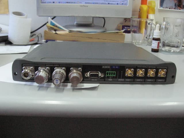
Click to zoom
Application Details
- Equipment Class
- DTS - Digital Transmission System
- Date of Grant
- Mar 06, 2008
- Application Purpose
- Original Equipment
- Date of Application
- Mar 06, 2008
- Equipment Note
- 860M WITH WCE
- Frequency Range
- 2412.00000000 - 2462.00000000
- Country
- United States
Documents & Files
Document Text
Text extracted from the exhibit documents filed with the FCC. Open a document above to read the original.
Users Manual
P/N: 709C002901 REV: A00 Date: 09-JAN-2008 8 8 8 6 6 6 0 0 0 M M M w w w i i i t t t h h h W W W C C C E E E Installation and Configuration Guide Preface Material MA-860 Installation and Configuration Guide II MobileAccess 8391 Old Courthouse Road, Suite 300, Vienna, VA 22182 Tel: (866)436-9266, (703)848-0200 TAC: (800)787-1266, Fax: (703)848-0280 http://www.MobileAccess.com Preface Material MA-860 Installation and Configuration Guide III P P r r e e f f a a c c e e M M a a t t e e r r i i a a l l ©COPYRIGHT 2007, MOBILEACCESS NETWORKS INC.ALL RIGHTS RESERVED. M OBILEACCESSTM IS A REGISTERED TRADEMARK OF MOBILEACCESS.THIS DOCUMENT CONTAINS OTHER TRADEMARKS, TRADE NAMES AND SERVICE MARKS OF MOBILEACCESS AND OTHER ORGANIZATIONS, ALL OF WHICH ARE THE PROPERTY OF THEIR RESPECTIVE OWNERS. T HIS DOCUMENT CONTAINS CONFIDENTIAL AND PROPRIETARY INFORMATION OF MOBILEACCESS AND MAY NOT BE COPIED, TRANSMITTED, STORED IN A RETRIEVAL SYSTEM OR REPRODUCED IN ANY FORMAT OR MEDIA , IN WHOLE OR IN PART, WITHOUT THE PRIOR WRITTEN CONSENT OF MOBILEACCESS.INFORMATION CONTAINED IN THIS DOCUMENT SUPERSEDES ANY PREVIOUS MANUALS, GUIDES, SPECIFICATIONS, DATA SHEETS OR OTHER INFORMATION THAT MAY HAVE BEEN PROVIDED OR MADE AVAILABLE TO THE USER . T HIS DOCUMENT IS PROVIDED FOR INFORMATIONAL PURPOSES ONLY, AND MOBILEACCESS DOES NOT WARRANT OR GUARANTEE THE ACCURACY, ADEQUACY, QUALITY, VALIDITY, COMPLETENESS OR SUITABILITY FOR ANY PURPOSE OF THE INFORMATION CONTAINED IN THIS DOCUMENT. M OBILEACCESS RESERVES THE RIGHT TO MAKE UPDATES, IMPROVEMENTS AND ENHANCEMENTS TO THIS DOCUMENT AND THE PRODUCTS TO WHICH IT RELATES AT ANY TIME WITHOUT PRIOR NOTICE TO THE USER . MOBILEACCESS MAKES NO WARRANTIES, EXPRESS OR IMPLIED, INCLUDING, WITHOUT LIMITATION, THOSE OF MERCHANTABILITY AND FITNESS FOR A PARTICULAR PURPOSE, WITH RESPECT TO THIS DOCUMENT OR ANY INFORMATION CONTAINED HEREIN. Preface Material MA-860 Installation and Configuration Guide IV Policy for Warrantee and Repair MOBILEACCESS TESTS AND INSPECTS ALL ITS PRODUCTS TO VERIFY THEIR QUALITY AND RELIABILITY.MOBILEACCESS USES EVERY REASONABLE PRECAUTION TO ENSURE THAT EACH UNIT MEETS THEIR DECLARED SPECIFICATIONS BEFORE SHIPMENT .CUSTOMERS SHOULD ADVISE THEIR INCOMING INSPECTION , ASSEMBLY, AND TEST PERSONNEL ABOUT THE PRECAUTIONS REQUIRED IN HANDLING AND TESTING OUR PRODUCTS.MANY OF THESE PRECAUTIONS CAN BE FOUND IN THIS MANUAL . T HE PRODUCTS ARE COVERED BY THE FOLLOWING WARRANTIES: General Warranty MOBILEACCESS WARRANTS TO THE ORIGINAL PURCHASER ALL STANDARD PRODUCTS SOLD BY MOBILEACCESS TO BE FREE OF DEFECTS IN MATERIAL AND WORKMANSHIP FOR ONE (1) YEAR FROM DATE OF SHIPMENT FROM MOBILEACCESS.DURING THE WARRANTY PERIOD, M OBILEACCESS WILL REPAIR OR REPLACE ANY PRODUCT THAT MOBILEACCESS PROVES TO BE DEFECTIVE.THIS WARRANTY DOES NOT APPLY TO ANY PRODUCT THAT HAS BEEN SUBJECT TO ALTERATION , ABUSE, IMPROPER INSTALLATION OR APPLICATION, ACCIDENT, ELECTRICAL OR ENVIRONMENTAL OVER -STRESS, NEGLIGENCE IN USE, STORAGE, TRANSPORTATION OR HANDLING. Specific Product Warranty Instructions ALL MOBILEACCESS PRODUCTS ARE WARRANTED AGAINST DEFECTS IN WORKMANSHIP, MATERIALS AND CONSTRUCTION, AND TO NO FURTHER EXTENT .ANY CLAIM FOR REPAIR OR REPLACEMENT OF UNITS FOUND TO BE DEFECTIVE ON INCOMING INSPECTION BY A CUSTOMER MUST BE MADE WITHIN 30 DAYS OF RECEIPT OF SHIPMENT, OR WITHIN 30 DAYS OF DISCOVERY OF A DEFECT WITHIN THE WARRANTY PERIOD. THIS WARRANTY IS THE ONLY WARRANTY MADE BY MOBILEACCESS AND IS IN LIEU OF ALL OTHER WARRANTIES, EXPRESSED OR IMPLIED. MOBILEACCESS SALES AGENTS OR REPRESENTATIVES ARE NOT AUTHORIZED TO MAKE COMMITMENTS ON WARRANTY RETURNS. Returns IN THE EVENT THAT IT IS NECESSARY TO RETURN ANY PRODUCT AGAINST ABOVE WARRANTY, THE FOLLOWING PROCEDURE SHALL BE FOLLOWED: 1. R ETURN AUTHORIZATION IS TO BE RECEIVED FROM MOBILEACCESS PRIOR TO RETURNING ANY UNIT.ADVISE MOBILEACCESS OF THE MODEL, SERIAL NUMBER, AND DISCREPANCY.THE UNIT MAY THEN BE FORWARDED TO MOBILEACCESS, TRANSPORTATION PREPAID.DEVICES RETURNED COLLECT OR WITHOUT AUTHORIZATION MAY NOT BE ACCEPTED . 2. P RIOR TO REPAIR,MOBILEACCESS WILL ADVISE THE CUSTOMER OF OUR TEST RESULTS AND ANY CHARGES FOR REPAIRING CUSTOMER-CAUSED PROBLEMS OR OUT -OF-WARRANTY CONDITIONS ETC. 3. R EPAIRED PRODUCTS ARE WARRANTED FOR THE BALANCE OF THE ORIGINAL WARRANTY PERIOD, OR AT LEAST 90 DAYS FROM DATE OF SHIPMENT . Limitations of Liabilities MOBILEACCESS'S LIABILITY ON ANY CLAIM, OF ANY KIND, INCLUDING NEGLIGENCE FOR ANY LOSS OR DAMAGE ARISING FROM, CONNECTED WITH, OR RESULTING FROM THE PURCHASE ORDER, CONTRACT, QUOTATION, OR FROM THE PERFORMANCE OR BREACH THEREOF, OR FROM THE DESIGN, MANUFACTURE, SALE, DELIVERY, INSTALLATION, INSPECTION, OPERATION OR USE OF ANY EQUIPMENT COVERED BY OR FURNISHED UNDER THIS CONTACT , SHALL IN NO CASE EXCEED THE PURCHASE PRICE OF THE DEVICE WHICH GIVES RISE TO THE CLAIM. EXCEPT AS EXPRESSLY PROVIDED HEREIN, MOBILEACCESS MAKES NO WARRANTY, EXPRESSED OR IMPLIED, WITH RESPECT TO ANY GOODS, PARTS AND SERVICES PROVIDED IN CONNECTION WITH THIS AGREEMENT INCLUDING, BUT NOT LIMITED TO, THE IMPLIED WARRANTIES OF MERCHANTABILITY AND FITNESS FOR A PARTICULAR PURPOSE. MOBILEACCESS SHALL NOT BE LIABLE FOR ANY OTHER DAMAGE INCLUDING, BUT NOT LIMITED TO, INDIRECT, SPECIAL OR CONSEQUENTIAL DAMAGES ARISING OUT OF OR IN CONNECTION WITH FURNISHING OF GOODS, PARTS AND SERVICE HEREUNDER, OR THE PERFORMANCE, USE OF, OR INABILITY TO USE THE GOODS, PARTS AND SERVICE. Preface Material MA-860 Installation and Configuration Guide V Reporting Defects THE UNITS WERE INSPECTED BEFORE SHIPMENT AND FOUND TO BE FREE OF MECHANICAL AND ELECTRICAL DEFECTS. EXAMINE THE UNITS FOR ANY DAMAGE THAT MAY HAVE BEEN CAUSED IN TRANSIT.IF DAMAGE IS DISCOVERED, FILE A CLAIM WITH THE FREIGHT CARRIER IMMEDIATELY .NOTIFY MOBILEACCESS AS SOON AS POSSIBLE. NOTE: KEEP ALL PACKING MATERIAL UNTIL YOU HAVE COMPLETED THE INSPECTION WARNING: TO COMPLY WITH FCC RF EXPOSURE COMPLIANCE REQUIREMENTS, ANTENNAS USED FOR THIS PRODUCT MUST BE FIXED MOUNTED ON IND…
Text truncated - open the document above for the full version.
Users Manual
Infrastructure Preparation MA-860 Installation and Configuration Guide 19 3.5.3 AP Termination A 50 Ω ΩΩ Ω termination is required on each unused AP port. The type of termination is vendor specific. Vendor Model Termination Cisco 1242 RP-TNC 50 ohm terminators Aruba AP-70 RP-SMA 50 ohm terminators Trapeze MP-422 RP-SMA 50 ohm terminators Colubris MAP-330 RP-SMA 50 ohm terminators Meru AP-200 RP-SMA 50 ohm terminators 3.5.4 IDF Access Point Planning MobileAccess recommends that each independent IDF Telecom closet is adequately planned for installation of the access points to increase the amount of isolation and reduce the amount of RF leakage between access points. MobileAccess recommends the following options for access point installation: •Wall Mounting of MobileAccess supported Access Point •Rack-Mounting of MobileAccess supported Access Points Utilizing the mounting hardware distributed from each supported access point vendor, Access point can be mounted on a wall within the IDF or telecom closet and connected with the appropriate low-loss jumper cables to the appropriate 860 WLAN module interface ports. MobileAccess has also found that mounting the access points in a 19” rack system has proven to be effective against RF leakage between access points. In this configuration, two access points can be installed per 19” shelving unit which takes up 1U of space per two access points. Installation MA-860 Installation and Configuration Guide 20 4 I I n n s s t t a a l l l l a a t t i i o o n n This chapter contains the installation and connection procedures for various installation configurations. The MobileAccess 860 WLAN Module and system architecture may be installed in the following configurations: 4.1 Accessory Kits Verify that the supplied accessory kit corresponds to your installation. The accessory kits include a bracket, the required cables and accessories. Part Number Description AK-860-1000 RHU 1000 860 WLAN Accessory Mounting Kit AK-860-1200 RHU 1200 860 WLAN Accessory Mounting Kit AK-860-MDLT Modulite 860 WLAN Accessory Mounting Kit AK-860-2000 MRC 2000 860 WLAN Accessory Mounting Kit AK-860-2000L MRC 2000L 860 WLAN Accessory Mounting Kit AK-860-SA Stand alone Mounting Kit AK-860-PS-9.8V-75W (Optional) Redundant Power Supply Kit 4.2 Access Point Installation (Recommendation) MobileAccess recommends that each independent IDF Telecom closet is adequately planned for installation of the access points to increase the amount of isolation and reduce the amount of RF leakage between access points. MobileAccess recommends the following options for access point installation: •Wall Mounting of MobileAccess supported Access Point •Rack-Mounting of MobileAccess supported Access Points Utilizing the mounting hardware distributed from each supported access point vendor, Access point can be mounted on a wall within the IDF or telecom closet and connected with the appropriate low-loss jumper cables to the appropriate 860 WLAN module interface ports. Installation MA-860 Installation and Configuration Guide 21 MobileAccess has also found that mounting the access points in a 19” rack system has proven to be effective against RF leakage between access points. In this configuration as detailed in the picture below, two access points can be installed per 19” shelving unit which takes up 1U of space per two access points. Installation MA-860 Installation and Configuration Guide 22 4.3 Wi-Fi Coverage Expander (WCE) Installation Note: It is assumed the antennas have already been installed at the remote locations. A WCE unit is installed near each antenna. The WCE can be installed in the following configurations: •Tie-Wrap / Wire-Tie to a fixture •Wall Mounted – using four screws •In-line with the coax cables The WCE will be connected on one side to a 0.5'' low loss coaxial cable (typically running to a remote wiring closet), and to the Passive Broadband Antenna usually through a jumper (flexible 1' coax cable). The following sections illustrate each type of WCE installation. 0.5'' low loss coaxial cable Up to 250 ft 1' coax cable Installation MA-860 Installation and Configuration Guide 23 4.3.1 WCE Tie to Fixture Installation Use the two mounting slots used to affix the unit to any available building infrastructure via a wire-tie or tie-strap. 4.3.2 WCE Wall Mounted Using Four Screws Secure the WCE using four standard drywall screws (3/16” in diameter). Installation MA-860 Installation and Configuration Guide 24 4.3.3 In Line with Coax Cables WCE’s light design enables connecting it between the two coax cables without additional support. NOTE: The bending moment for ½” coax cable = 3lbs per foot. 4.4 860 WLAN Module Installation MA 860 can be mounted in the following configurations: •Standalone – mounted directly on the wall with four screws •Mounted onto an MA 1000 RHU •Mount as add-on to an MA 1000 RHU with an MA 1200 add-on unit •Add-on to a MA 2000 system To install the unit •Depending on your installation mount the unit on the IDF or telecom Closet wall (standalone installation) or assemble it onto the MA system (when converged with other MA systems) •Record location and serial number of MA860 unit Installation MA-860 Installation and Configuration Guide 25 4.5 MA-860 Unit Installation and Connections MobileAccess MA-860 is typically installed in the IDF or Telecom Closet of each floor to which WLAN coverage is to be supported. The accessories, mounting and installation procedures vary depending on the installation configuration. 4.5.1 Standalone Wall Mount Installation Figure 4-1. MA-860 Standalone Installation Configuration NOTE: It is recommended to record the location of the units and IP address according to the MAC addresses on the sticker at the rear of the units near the Ethernet port. Although it is not required for a stand-alone installation, it is recommended to set the supplied cable 705102101 aside (usually used when MA-860 is installed in an add-on configuration).You will need it if yo…
Text truncated - open the document above for the full version.
Users Manual
Installation MA-860 Installation and Configuration Guide 39 4.7.2 Power Connections to MA860 Unit •Only Main PS is connected to the unit – connect directly to 20-48V side of the PWR connector. •Main and Redundant PSs connected to the unit – connect the provided splitter cable to the unit and the Main and Redundant PSs to the appropriate connectors as shown below. Connection to Main Power Supply only Connection to splitter cable for installations with redundant PS To Main PS To Redundant PS MA-860 Installation and Configuration Guide 40 5 P P o o w w e e r r - - u u p p a a n n d d P P r r o o v v i i s s i i o o n n i i n n g g t t h h e e U U n n i i t t Upon power-up, MA-860 automatically performs WCE, WiFi Coverage Expander auto-discovery. It is recommended to locally connect to the unit using a computer running the telnet session to configure the local configuration options defined below. Following the initial setup and configuration MobileAccess recommends that the administrator verifies that all connected antennas are detected via the Web GUI or Engineering GUI, to perform the adjustment procedures and to verify that the unit is operating properly. MA860 is by default configured with a static IP address. (It may also be configured for DHCP). Once the MA860 IP address is defined and it is connected to the network, it can be remotely managed via a Web access connection. This section provides the following information: •Unit power-up and procedures performed by the unit upon power-up •Opening a session from the MA-860 Engineering Tool application •Verifying all antennas are connected •Performing adjustment procedures 5.1 Power-up and WCE Auto-discovery To power-up the unit Connect the power to the PWR connector located on the MA-860 as defined in Section 4.7. Unit initialization and WCE auto-discovery Upon power-up, the unit performs discovery of the WCE units during which time the RUN LED (located on the front panel) is constant GREEN. This will take between one to two minutes. If you have connected the 860 WLAN Module via the Web GUI or Engineering UI before the auto-discovery process was completed, the dialog will show Auto-discovery in process. After the initial discovery procedure has been completed, the RUN LED continuously flickers green indicating normal operation. Note: Configuration changes corresponding to the addition or removal of WCE units can be remotely performed at any time via the Web GUI to access the unit. Power-up and Provisioning the Unit MA-860 Installation and Configuration Guide 41 5.2 System Setup Configuration Before deploying the device in the field, it is recommended that all system level configurations are configured on the 860 WLAN module as defined in section 5.2 5.2.1.1 Assigning Network Parameters The unit is factory set with the following static IP address: IP address: 192.168.1.1 Subnet mask: 255.255.0.0 Default GW: 192.168.254.254 •Change the static address using Telnet as described in section 5.2.1.2 Note: For networks with DHCP – refer to section 6.2.2 •To set the SNMP parameters – refer to section 5.2.1.3. 5.2.1.2 Changing the Static IP Address The static IP address is changed from the Telnet window. To change the static IP address 1. Set your laptop IP to the same subnet as the static IP address assigned to the Repeater (e.g 192.168.1.2) 2. Connect the unit to your laptop with a cross cable. 3. Click the Windows Start option, choose Run and type Telnet and press Enter. 4. At the prompt Microsoft Telnet> o 192.168.1.1 9999. Press Enter. 5. Click OK and immediately press Enter to go into Setup Mode. The current settings will be displayed, followed by the Change Setup menu. Change Setup: 0 Server configuration 1 Channel 1 configuration 3 SNMP configuration 8 exit without save 9 save and exit Your choice 0 6. Enter 0 (Server Configuration). 7. You will be prompted to change the IP address one byte at a time –Enter the new value for each byte as you are prompted and press Enter. For example, the value entered below is 192.168.10.55 IP Address : (000) 192.(000) 168.(000) 10.(000) 55 Power-up and Provisioning the Unit MA-860 Installation and Configuration Guide 42 8. You will be are prompted to set the Gateway, Netmask, telnet Config password and to Change the DHCP device name. IP Address : (000) .(000) .(000) .(000) Set Gateway IP Address (Y) ? Gateway IP Address : (192) .(168) .(010) .(245) Netmask: Number of Bits for Host Part (0=default) (16) Change telnet config password (N) ? Change DHCP device name (not set) ? (N) ? 9. Press Enter to run through the rest of the parameters. When the Setup Menu is displayed again, select 9 – Save and Exit. 5.2.1.3 Setting SNMP Parameters 1. Click the Windows Start option, choose Run and type Telnet and press Enter. 2. At the prompt Microsoft Telnet> o xxxx.xxxx.xxxx.xxxx 9999 (where xxxx.. is the IP address of the unit). Press Enter. 3. Click OK and immediately press Enter to go into Setup Mode. The current settings will be displayed, followed by the Change Setup menu. Change Setup: 0 Server configuration 1 Channel 1 configuration 3 SNMP configuration 8 exit without save 9 save and exit Your choice 3 4. Enter 3 (SNMP Configuration). 5. Set the SNMP Read and Write community names and the SNMP traps destination addresses (up to three addresses can be defined). SNMP community name for read (): public SNMP community name for write (): private Enter IP addresses for SNMP traps: 1: (000) 192.(000) 168.(000) 10.(000) 22 2: (000) .(000) .(000) .(000) 3: (000) .(000) .(000) .(000) 6. Press Enter to run through the rest of the parameters. When the Setup Menu is displayed again, select 9 – Save and Exit. Power-up and Provisioning the Unit MA-860 Installation and Configuration Guide 43 5.3 Default Login and User Account Levels You may login to the MA 860 unit through any Web browser or 860 WLAN Engineering GUI. The available login credentials and default passwords are defined below: •Operator (oper) – monitoring options only…
Text truncated - open the document above for the full version.
Cover Letter(s)
Making Wireless an Indoor State of Mind FCC Confidential Authorization 13/01/2008 FEDERAL COMMUNICATIONS COMMISSIONS Authorization and Evaluation Division 7435 Oakland Mills Road Columbia, MD 21046 Subject: Confidentiality Request regarding application for certification of FCC ID: OJFMA860WME In accordance with Sections 0.457 and 0.459 of the Commission’s Rules, MobileAccess Networks hereby requests long-term confidential treatment of information accompanying this application as outlined below: Conf 860M With WCE BlkDia.pdf Conf 860M With WCE PartsLst 1.pdf Conf 860M With WCE PartsLst 2.pdf Conf 860M With WCE Schem 1.pdf Conf 860M With WCE Schem 2.pdf The above materials contain proprietary and confidential information not customarily released to the public. The public disclosure of these materials provides unjustified benefits to its competitors in the market. Sincerely, Steve Blum Product Manager MobileAccess Networks 8391 Old Courthouse Rd Suite 300 Vienna VA 22182-3819 Unwired: 541-758-2880 Making Wireless an Indoor State of Mind On the web at www.MobileAccess.com
Cover Letter(s)
Making Wireless an Indoor State of Mind FCC Confidential Authorization Date: 28/02/2008 To: Timco Engineering Inc. To Whom It May Concern We hereby authorize Mr. Shaike Raz of I.T.L. (Product Testing) Ltd (ITL) to sign Form 731 on our behalf regarding the FCC ID Certification Process for the following application: 860M with WCE System FCC ID: OJFMA860WME Thank you, Sincerely, Steve Blum Product Manager MobileAccess Networks 8391 Old Courthouse Rd Suite 300 Vienna VA 22182-3819 Unwired: 541-758-2880 Making Wireless an Indoor State of Mind On the web at www.MobileAccess.com
Cover Letter(s)
file:///W|/M/MOBILE_OJF/3674IC7/cust%20reply_70110%20to%20TCB%20question%20%231.htm From: Emc [[email protected]] Sent: Thursday, January 10, 2008 10:19 AM To: [email protected] Cc: Leonid Pakman Subject: RE: TIMCO-TCB/Request for addtional information - MOBILE ACCESS NETWORKS - FCC ID: OJFMA860WCE Timco Job Number 3674IC7 Hi Bruno, 1. The following is the response to your Dec. 3, 2007 email which included comments to the original application of OJFMA860WCE, based on our recent telephone conversation and correspondences. 2. We plan to upload all the revised reports, Forms 731, and exhibits by 14 January 2008. 3. Concerning item 1: The 860M with WCE is not a repeater. This device is an external radio frequency amplifier (ERFPA). 4. Concerning item 2: We will upload new Forms 731, 2 for each Access Point (1 for 2.4 GHz transmitter; 1 for 5 GHz transmitter) application including separate reports. 5. Concerning item 3: We will upload: a. Photos showing the label locations on each access point b. Photos showing the label locations on the combiner box and amplifier box. All 5 FCC ID#'s will be placed on each box. 6. Concerning item 4: The 860M With WCE will be marketed only as a system with the 5 tested access points. The user manual and external packaging include a notification of which access points are to be used with the 860M With WCE. Concerning labeling, see item 5 above. A reversed polarity connector is used on the access points' RF output, to satisfy unique coupling with the 860M. 7. Concerning item 5: As already discussed and agreed before, the cellular/PCS devices signals are not routed via the amplifier (only 802.11 signals). Therefore no Parts 22/24 tests are required. 8. Concerning item 8: Only maximum output power as detailed in the device test report will be on the two forms 731 (1 for each transmitter), for each of the 5 access points. 9. Concerning item 7: Upper and lower tested frequencies will be listed in the forms 731 separately for each transmitter of each of the 5 access points. 10. Concerning item 8: We took new photos with better resolution which will be uploaded. 11. Concerning item 9: Separate reports for Section 15.247 and 15.407 will be uploaded. 12. Concerning item 10: Additional testing of a 3rd operation frequency for each NII band was completed and included in the test reports. 13. Concerning item 11: Spurious radiated emission results are detailed in Sections 4; 5 of each new test report. file:///W|/M/MOBILE_OJF/3674IC7/cust%20reply_70110%20to%20TCB%20question%20%231.htm (1 of 3)2/7/2008 3:22:06 PM file:///W|/M/MOBILE_OJF/3674IC7/cust%20reply_70110%20to%20TCB%20question%20%231.htm 14. Concerning item 12: a. Section 10 shows data for conducted test for 2.4 GHz band edges. b. Spurious radiated emission tests (section 5) included the 2,4385 MHz to 2,500 MHz restricted band. 15. Concerning item 13: Band edges at 5.250 GHz when operating at 5.24 GHz were retested for all 5 access points to show compliance with 20 dBc requirement. See Section 11 of the new reports. 16. Concerning item 14: Spurious radiation levels results are included in sections 4; 5 of each new test report. 17. Concerning item 15: Tester name and signature was added for all tests in the new reports. 18. Concerning item 16: The test setup diagram describes the 2 nd configuration (860M and WCE+1000). The MA2000 product family is identical to the MA1000 product family as far as it concerns to the 860M and WCE interface. This is why we are stating that all described configurations (860M and WCE stand alone, 860M and WCE+1000, 860M and WCE+2000) are supported. Both the MA-1000 and MA-2000 handle cellular services and have their own FCC ID # approval. Also see the response to item 5 above, explaining that cellular service testing is not applicable for these applications. 19. Concerning item 17: It is stated in the test reports and user manual that the maximum antenna gain is 7dBi. Any 3PE antenna of equal or lower gain as required by the FCC can be used. See revised information concerning antennas in Section 3.4.1 of the revised user manual. 20. Concerning item 18: The revised user manual (Section 3.5.1) includes the list of all 5 access points. 21. The following exhibits are common to all 5 applications: External photos of the 860M and WCE units Internal Photos of the 860M and WCE units FCC Labels for 860M and WCE units Operational description Block diagram Parts Lists Schematics Test setup photos file also includes conducted tests setups of all 5 access points. Regards Shaike Raz EMC Laboratory Manager EMC Laboratory ITL (Product Testing) Ltd. Kfar Bin Nun Israel Tel: +972-8-979-7799 Fax: +972-8-979-7702 Email: [email protected]/[email protected] http://www.itl.co.il This e-mail message may contain privileged or confidential information. If you are not the intended recipient, you may not disclose, use, disseminate, distribute, copy or rely upon this message or file:///W|/M/MOBILE_OJF/3674IC7/cust%20reply_70110%20to%20TCB%20question%20%231.htm (2 of 3)2/7/2008 3:22:06 PM file:///W|/M/MOBILE_OJF/3674IC7/cust%20reply_70110%20to%20TCB%20question%20%231.htm attachment in any way. If you received this e-mail message in error, please return by forwarding the message and its attachments to the sender. file:///W|/M/MOBILE_OJF/3674IC7/cust%20reply_70110%20to%20TCB%20question%20%231.htm (3 of 3)2/7/2008 3:22:06 PM
Cover Letter(s)
RE: TIMCO-TCB/Request for additional information - MOBILE ACCESS NETWORKS - FCC ID: OJFMA860WCE Timco Job Number 3674IC7 From: Emc [[email protected]] Sent: Tuesday, February 05, 2008 7:46 AM To: [email protected] Cc: Leonid Pakman; Bruno Clavier; Shaike Raz Subject: RE: TIMCO-TCB/Request for additional information - MOBILE ACCESS NETWORKS - FCC ID: OJFMA860WCE Timco Job Number 3674IC7 Hello: Please see below ITL/Mobile Access responses to the above subject request for additional information. We plan to submit in the next 2 days the reports for the additional tests performed in the last days, revised Forms 731, user manual, test set up photos. We are looking forward to completing this job this week. Thanks for your help and cooperation. 1. Concerning item 1: Revised Forms 731 signed by the ITL authorized representative, including an authorization letter from Mobile Access will be uploaded. 2. Concerning Item 2: The revised Form 731 will include the frequency bands as tested including maximum conducted output power for each band. 3. Concerning items 3, 4, 6: A revised user manual will be uploaded. 4. Concerning item 5: Professional installation is covered by page VII of the user manual and installation instructions in Section 4 of the user manual. 5. Concerning item 7: The 860M is used with the WCE only. 6. Concerning item 8: file:///W|/M/MOBILE_OJF/3674IC7/cust%20reply_80205%20to%20TCB%20Question%20%232.htm (1 of 4)2/7/2008 3:22:05 PM RE: TIMCO-TCB/Request for additional information - MOBILE ACCESS NETWORKS - FCC ID: OJFMA860WCE Timco Job Number 3674IC7 New photos will be uploaded. 7. Concerning item 9: Under this application only the 860M+WCE configuration is applicable (see page 5 of the user manual). 8. Concerning item 10: The WCE is the "amplifier box" and the 860M is the "combiner box". 9. Concerning item 11: The revised user manual includes specific antennas in addition to antenna gain and type information (See Section 3.4.1). 10. Concerning item 12.1: 802.11 b/g and 802.11a signals are non-coordinated, therefore composite power does not apply. 11. Concerning item 12.2: The product was tested for conducted and radiated emissions for signals of 802.11b/g + 802.11a +licensed. In addition, intermodulation was also tested with the above signals (See Section 26 of the test reports). 12. Concerning item 12.3: The original tests were performed with one access point of each model. We performed additional testing on a configuration with 4 identical Cisco Model 1242 access points. See information in ITL additional test reports no.'s E764115.00 and E764116.00. 13. Concerning item 12.4: This type of test is not part of Section 15.247; 15.407 or the FCC guidance document for prior RF distribution amplifier (850A). Also, it's applicable only for FCC Parts 22/24/90 tests not performed under this application. 14. Concerning item 12.5: file:///W|/M/MOBILE_OJF/3674IC7/cust%20reply_80205%20to%20TCB%20Question%20%232.htm (2 of 4)2/7/2008 3:22:05 PM RE: TIMCO-TCB/Request for additional information - MOBILE ACCESS NETWORKS - FCC ID: OJFMA860WCE Timco Job Number 3674IC7 A complete system with 4 identical access points Cisco Model 1242, including 802.11b/g+802.11a +licensed signals was re-tested. See ITL test reports E764115.00 and E764116.00. 15. Concerning item 12.6: Intermodulation emissions tests were performed including 802.11b/g+802.11a+licensed signals operating simultaneously. The transmission frequencies were set to minimum separation to generatet maximum levels of 3rd order or other odd order signals. The access point was the type having maximum RF output power. The transmission frequencies were: 802.11b/g: 2412 MHz 802.11a: 5180 MHz CELL: 890 MHz PCS: 1985 MHz Regards Best Regards Shaike Raz EMC Laboratory Manager EMC Laboratory ITL (Product Testing) Ltd. Kfar Bin Nun Israel Tel: +972-8-979-7799 Fax: +972-8-979-7702 Email: [email protected]/[email protected] file:///W|/M/MOBILE_OJF/3674IC7/cust%20reply_80205%20to%20TCB%20Question%20%232.htm (3 of 4)2/7/2008 3:22:05 PM RE: TIMCO-TCB/Request for additional information - MOBILE ACCESS NETWORKS - FCC ID: OJFMA860WCE Timco Job Number 3674IC7 http://www.itl.co.il This e-mail message may contain privileged or confidential information. If you are not the intended recipient, you may not disclose, use, disseminate, distribute, copy or rely upon this message or attachment in any way. If you received this e-mail message in error, please return by forwarding the message and its attachments to the sender. file:///W|/M/MOBILE_OJF/3674IC7/cust%20reply_80205%20to%20TCB%20Question%20%232.htm (4 of 4)2/7/2008 3:22:05 PM
Cover Letter(s)
TIMCO ENGINEERING INC. TCB & FCB 849 NW State Road 45 FCC Approvals Newberry, Florida 32669 Industry Canada Approvals http://www.timcoengr.com Notified Body for Europe 888.472.2424 F 352.472.2030 email: [email protected] 1/22/2007 MR. SHAIKE RAZ ISRAEL TESTING LABORATORIES 972-897-9779 x9 972-897-9770 x2 [email protected] SUBJECT: MOBILE ACC…
Text truncated - open the document above for the full version.
Contact Information
Applicant
Dana Whitney(Director of Operations and Program)
Test Firm
Israel Testing LaboratoriesIIan Cohen
Technical Specifications
| # | Rule Parts | Frequency Range | Power Output |
|---|---|---|---|
| 1 | 15C | 2.41 GHz - 2.46 GHz | 182.00 mW |
Other Applications from Corning Optical Communication LLC

OJFE62-N3-7US
Aug 29, 2024Remote Unit, Radio Node
Equipment Class
B2I - Part 20 Industrial Booster (CMRS)
OJFDHRU-G2-19
Apr 09, 2024HRU Digital High Power Amplifier Module supporting PCS
Equipment Class
B2I - Part 20 Industrial Booster (CMRS)
OJFDLRUG2678
Oct 17, 2023Low Band dRAU
Equipment Class
B2I - Part 20 Industrial Booster (CMRS)
OJFDMRUG22325
Jul 31, 2023digital Medium-power Remote Unit
Equipment Class
B2I - Part 20 Industrial Booster (CMRS)
OJFDMRUG2678
Jul 30, 2023digital Medium-power Remote Unit
Equipment Class
B2I - Part 20 Industrial Booster (CMRS)