OJFVELTE700MBVE LTE 700MHz MIXED BAND MIMO
Corning Optical Communication LLC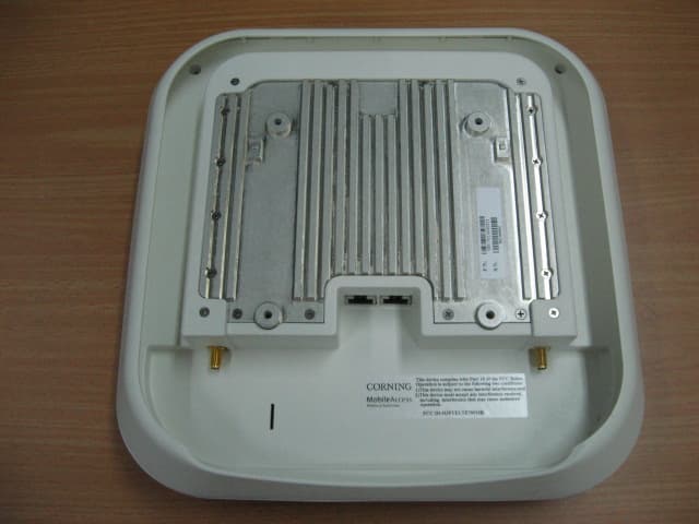
Click to zoom
Application Details
- Equipment Class
- TNB - Licensed Non-Broadcast Station Transmitter
- Date of Grant
- Sep 11, 2011
- Application Purpose
- Original Equipment
- Date of Application
- Sep 11, 2011
- Equipment Note
- VE LTE 700MHz MIXED BAND MIMO
- Frequency Range
- 728.00000000 - 758.00000000
- Country
- United States
Documents & Files
Document Text
Text extracted from the exhibit documents filed with the FCC. Open a document above to read the original.
Users Manual
MobileAccessVE Mixed-Band LTE 700 MHz Instant Coverage Solution User Manual P/N: 709C006211 REV: A00 Date: AUG, 2011 Preface Material Mixed Band LTE 700 MHz MobileAccessVE Instant Coverage Solution User Manual II Corning MobileAccess 8391 Old Courthouse Road, Suite 300, Vienna, VA 22182 Tel: +1(866)436-9266, +1(703)848-0200 TAC: +1(800)787-1266, Fax: +1(703)848-0280 www.corning.com/mobileaccess Preface Material Mixed Band LTE 700 MHz MobileAccessVE Instant Coverage Solution User Manual III Preface Material © Copyright 2011, MobileAccess. All Rights Reserved. This document contains confidential and proprietary information of MobileAccess and may not be copied, transmitted, stored in a retrieval system or reproduced in any format or media, in whole or in part, without the prior written consent of MobileAccess. Information contained in this document supersedes any previous manuals, guides, specifications, data sheets or other information that may have been provided or made available to the user. This document is provided for informational purposes only, and MobileAccess does not warrant or guarantee the accuracy, adequacy, quality, validity, completeness or suitability for any purpose of the information contained in this document. MobileAccess reserves the right to make updates, improvements and enhancements to this document and the products to which it relates at any time without prior notice to the user. MOBILEACCESS MAKES NO WARRANTIES, EXPRESS OR IMPLIED, INCLUDING, WITHOUT LIMITATION, THOSE OF MERCHANTABILITY AND FITNESS FOR A PARTICULAR PURPOSE, WITH RESPECT TO THIS DOCUMENT OR ANY INFORMATION CONTAINED HEREIN. Policy for Warrantee and Repair MobileAccess tests and inspects all its products to verify their quality and reliability. MobileAccess uses every reasonable precaution to ensure that each unit meets their declared specifications before shipment. Customers should advise their incoming inspection, assembly, and test personnel about the precautions required in handling and testing our products. Many of these precautions can be found in this manual. The products are covered by the following warranties: General Warranty MobileAccess warrants to the original purchaser all standard products sold by MobileAccess to be free of defects in material and workmanship for one (1) year from date of shipment from MobileAccess. During the warranty period, MobileAccess will repair or replace any product that MobileAccess proves to be defective. This warranty does not apply to any product that has been subject to alteration, abuse, improper installation or application, accident, electrical or environmental over-stress, negligence in use, storage, transportation or handling. Specific Product Warranty Instructions All MobileAccess products are warranted against defects in workmanship, materials and construction, and to no further extent. Any claim for repair or replacement of units found to be defective on incoming inspection by a customer must be made within (30) days of receipt of shipment, or within (30) days of discovery of a defect within the warranty period. This warranty is the only warranty made by MobileAccess and is in lieu of all other warranties, expressed or implied. MobileAccess sales agents or representatives are not authorized to make commitments on warranty returns. Preface Material Mixed Band LTE 700 MHz MobileAccessVE Instant Coverage Solution User Manual IV Returns In the event that it is necessary to return any product against above warranty, the following procedure shall be followed: 1. Return authorization is to be received from MobileAccess prior to returning any unit. Advise MobileAccess of the model, serial number, and discrepancy. The unit may then be forwarded to MobileAccess, transportation prepaid. Devices returned collect or without authorization may not be accepted. 2. Prior to repair, MobileAccess will advise the customer of our test results and any charges for repairing customer-caused problems or out-of-warranty conditions etc. 3. Repaired products are warranted for the balance of the original warranty period, or at least 90 days from date of shipment. Limitations of Liabilities MobileAccess's liability on any claim, of any kind, including negligence for any loss or damage arising from, connected with, or resulting from the purchase order, contract, quotation, or from the performance or breach thereof, or from the design, manufacture, sale, delivery, installation, inspection, operation or use of any equipment covered by or furnished under this contact, shall in no case exceed the purchase price of the device which gives rise to the claim. EXCEPT AS EXPRESSLY PROVIDED HEREIN, MOBILEACCESS MAKES NO WARRANTY, EXPRESSED OR IMPLIED, WITH RESPECT TO ANY GOODS, PARTS AND SERVICES PROVIDED IN CONNECTION WITH THIS AGREEMENT INCLUDING, BUT NOT LIMITED TO, THE IMPLIED WARRANTIES OF MERCHANTABILITY AND FITNESS FOR A PARTICULAR PURPOSE. MOBILEACCESS SHALL NOT BE LIABLE FOR ANY OTHER DAMAGE INCLUDING, BUT NOT LIMITED TO, INDIRECT, SPECIAL OR CONSEQUENTIAL DAMAGES ARISING OUT OF OR IN CONNECTION WITH FURNISHING OF GOODS, PARTS AND SERVICE HEREUNDER, OR THE PERFORMANCE, USE OF, OR INABILITY TO USE THE GOODS, PARTS AND SERVICE. Reporting Defects The units were inspected before shipment and found to be free of mechanical and electrical defects. Examine the units for any damage that may have been caused in transit. If damage is discovered, file a claim with the freight carrier immediately. Notify MobileAccess as soon as possible. Note: Keep all packing material until you have completed the inspection Safety Warnings To comply with FCC RF exposure compliance requirement, adhere to the following warnings: Warning! The Access Pod with its built-in antenna must be installed with a separation distance of at least 20cm from all persons and must not be located in conjunction with any other antenna. Warning! The outside antenna must be installed with a separation of at least 20cm from all pe…
Text truncated - open the document above for the full version.
Cover Letter(s)
Making Wireless an Indoor State of Mind FCC Confidential Authorization Date: 28 August 2011 FEDERAL COMMUNICATIONS COMMISSIONS Authorization and Evaluation Division 7435 Oakland Mills Road Columbia, MD 21046 Subject: Confidentiality Request regarding application for certification of FCC ID: : OJFVELTE700MB In accordance with Sections 0.457 and 0.459 of the Commission’s Rules, MobileAccess Networks hereby requests long-term confidential treatment of information accompanying this application as outlined below: CONF APPENDIX VE LTE 700 MB VAP BlkDia.pdf CONF APPENDIX VE LTE 700 MB VCU BlkDia.pdf CONF APPENDIX VE LTE 700 MB VCU combiner PartsLst.pdf CONF APPENDIX VE LTE 700 MB VCU digital PartsLst.pdf CONF APPENDIX VE LTE 700 MB VCU RF PartsLst.pdf CONF APPENDIX VE LTE 700 MB VCU splitter PartsLst.pdf CONF APPENDIX VE LTE 700 MB VCU Reference PartsLst.pdf CONF APPENDIX VE LTE 700 MB VAP digital PartsLst.pdf CONF APPENDIX VE LTE 700 MB VAP RF PartsLst.pdf CONF APPENDIX VE LTE 700 MB VCU combiner Schem.pdf CONF APPENDIX VE LTE 700 MB VCU digital Schem.pdf CONF APPENDIX VE LTE 700 MB VCU RF Schem.pdf CONF APPENDIX VE LTE 700 MB VCU splitter Schem.pdf CONF APPENDIX VE LTE 700 MB VCU Reference Schem.pdf CONF APPENDIX VE LTE 700 MB VAP digital Schem.pdf CONF APPENDIX VE LTE 700 MB VAP RF Schem.pdf The above materials contain proprietary and confidential information not customarily released to the public. The public disclosure of these materials provides unjustified benefits to its competitors in the market. Sincerely, Steve Blum Product Manager MobileAccess Networks 8391 Old Courthouse Rd Suite 300 Vienna VA 22182-3819 Unwired: 541-758-2880 Making Wireless an Indoor State of Mind On the web at www.MobileAccess.com
Cover Letter(s)
Making Wireless an Indoor State of Mind FCC Confidential Authorization Date: 28 August 2011 To: Timco Engineering Inc. To Whom It May Concern We hereby authorize Mr. Shaike Raz of I.T.L. (Product Testing) Ltd (ITL) to sign Form 731 on our behalf regarding the FCC ID Certification Process for the following application: FCC ID: OJFVELTE700MB Thank you, Sincerely, Steve Blum Product Manager MobileAccess Networks 8391 Old Courthouse Rd Suite 300 Vienna VA 22182-3819 Unwired: 541-758-2880 Making Wireless an Indoor State of Mind On the web at www.MobileAccess.com
Cover Letter(s)
Making Wireless an Indoor State of Mind FCC Confidential Authorization Date: 28 August 2011 To: Timco Engineering Inc. To Whom It May Concern We hereby authorize Mr. Shaike Raz of I.T.L. (Product Testing) Ltd (ITL) to act on our behalf regarding the FCC ID Certification Process for the following application: FCC ID: OJFVELTE700MB Thank you, Sincerely, Steve Blum Product Manager MobileAccess Networks 8391 Old Courthouse Rd Suite 300 Vienna VA 22182-3819 Unwired: 541-758-2880 Making Wireless an Indoor State of Mind On the web at www.MobileAccess.com
ID Label/Location Info
2)This device must accept any interference received ,This device complies with Part 15 of the FCC Rules.Operation is subject to the following two conditions:1)This device may not cause harmful interference ,and operation. including interference that may cause undesired FCC ID: OJFVELTE700MB
Operational Description
Mobile Access system FCCID: OJFVELTE700MB The MobileAccessVE Multi-Band LTE 700 MHz MIMO solution provides enhanced, cost effective, in-building LTE MIMO Upper C or Lower A, B, C Block coverage for all enterprise environments. This solution is quickly and easily deployed using the existing cable infrastructure to provide instant coverage without affecting existing LAN services or performance. MobileAccessVE Mixed-Band LTE 700 MHz solution interfaces with the Service Provider’s RF capacity sources, combines the MIMO wireless services with the Ethernet services and routes the combined services over the existing Ethernet infrastructure to strategically distributed Access Pods. The Access Pods are connected to standard RJ45 Ethernet jacks. They provide signal coverage and Ethernet connectivity for IP devices. MobileAccessVE Mixed-Band LTE 700MHz solution is simply implemented via two types of units: VE Control Unit (VCU)– Interfaces with the Service Provider’s RF capacity sources and VE Access Pods (VAPs). It combines the two wireless LTE MIMO channels with the Ethernet services and distributes them to the VAPs over CAT-5e/6 cables. Coverage can be expanded with Slave VCUs. The Master Unit can be configured to either support the Lower A,B,C and/or Upper C spectrum from the RF source. VE Access Pods (VAPs)– Two types of MIMO LTE VAPs, supporting Upper C or Lower A,B,C blocks (Model Dependent). Distributes LTE MIMO service and provides Ethernet/IP connectivity and PoE pass-through to connected IP appliances, such as Wi-Fi APs and IP phones.
Parts List/Tune Up Info
8391 Old Courthouse Road, Suite 300 Vienna, VA 22182 28 August 2011 Declaration Concerning the Mobile Access FCC ID: : OJFVELTE700MB No manual tune-up procedure required. Thank you, Steve Blum Product Manager MobileAccess Networks Inc. Office 541 758-2880 Mobile 541 990-3470
RF Exposure Info
2 44.2 300 733 300 cm mWf 2 47.2 300 741 300 cm mWf 2 50.2 300 751 300cm mWf R.F Exposure/Safety Calculation for VE LTE700 MB The E.U.T. isanin-building antenna distribution system, supporting a single frequency band. The“worst case” distance between the E.U.T. and the general population is10cm. Calculation of Maximum Permissible Exposure (MPE) Based on Section 1.1307(b)(1) Requirements (a)FCCOccupational userlimit at733 MHz is: FCC Occupational user limit at 741 MHz is: FCC Occupational user limit at 751 MHz is: Using table 1 of Section 1.1310 limit for general population/uncontrolled exposures, the above level is an average over 30 minutes. (b)The power density produced by the E.U.T. is P t - TransmittedPeakPower(worst case) G T - Antenna Gain R- Distance from Transmitter 2 4R GP S tt (c)Peak power density: Operation Frequency ModulationPt (mW) Antenna type G T (dBi)R (cm) S AV (mW/cm 2 ) Spec (mW/cm 2 ) QPSK27.4External10100.2182.44 16QAM26.6External10100.2122.44733 MHz. 64QAM25.7External10100.2052.44 QPSK25.9External10100.2062.47 16QAM27.2External10100.2162.47741 MHz 64QAM26.9External10100.2142.47 QPSK27.0External10100.2152.50 16QAM27.2External10100.2162.50751 MHz 64QAM26.5External10100.2112.50
Test Report
Test Report E108660.00 Mobile Access Networks Page 1 of 82 FCC ACC M Ver 1.1 05Mayl 2000 DATE: 5 September 2011 I.T.L. (PRODUCT TESTING) LTD. FCC Radio Test Report for Mobile Access Networks Equipment under test: VE LTE 700MHz Mix Band MIMO Comprising : 1. VE Control Unit 2. VE Access Pod 1. VCU-MB-LTE700-12E 2. VAP-MB-LTE700E Written by: _____________________________ D. Shidlowsky, Documentation Approved by: _____________________________ A. Moses, Test Engineer Approved by: _____________________________ I. Raz, EMC Laboratory Manager This report must not be reproduced, except in full, without the written permission of I.T.L. (Product Testing) Ltd. This report relates only to items tested. Test Report E108660.00 Mobile Access Networks Page 2 of 82 FCC ACC M Ver 1.1 05Mayl 2000 Measurement/Technical Report for FCC ID: OJFVELTE700MB This report concerns: Original Grant: X Class II change: Class I change: Equipment type: Licensed Non-Broadcast Station Transmitter Limits used: 47CFR Part 27 Subpart C Measurement procedure used is ANSI C63.4-2003. Substitution Method used as in ANSI/TIA-603-D: 2010 Application for Certification Applicant for this device: prepared by: (different from "prepared by") Ishaishou Raz Steve Blum ITL (Product Testing) Ltd. Mobile Access Networks Kfar Bin Nun 8391 Old Courthouse Rd., Suite #300 D.N. Shimshon 99780 Vienna, VA. 22182 Israel U.S.A. e-mail [email protected] Tel: +1-541-758-2880 Fax: +1-703-848-0260 e-mail: [email protected] Test Report E108660.00 Mobile Access Networks Page 3 of 82 FCC ACC M Ver 1.1 05Mayl 2000 TABLE OF CONTENTS 1. GENERAL INFORMATION ------------------------------------------------------------------------------- 5 1.1 Administrative Information ................................................................................. 5 1.2 List of Accreditations ......................................................................................... 6 1.3 Product Description ........................................................................................... 7 1.4 Test Methodology .............................................................................................. 7 1.5 Test Facility ....................................................................................................... 7 1.6 Measurement Uncertainty ................................................................................. 8 2. SYSTEM TEST CONFIGURATION --------------------------------------------------------------------- 9 2.1 Justification ........................................................................................................ 9 2.2 EUT Exercise Software ..................................................................................... 9 2.3 Special Accessories .......................................................................................... 9 2.4 Equipment Modifications ................................................................................... 9 2.5 Configuration of Tested System ........................................................................ 9 3. CONDUCTED AND RADIATED MEASUREMENT TEST SET-UPS PHOTO --------------10 4. CONDUCTED EMISSION FROM AC POWER LINES -------------------------------------------13 4.1 Test Specification ............................................................................................ 13 4.2 Test Procedure ................................................................................................ 13 4.3 Measured Data ................................................................................................ 13 4.4 Test Instrumentation Used, Conducted Measurement ................................... 18 5. MAXIMUM PEAK OUTPUT POWER -----------------------------------------------------------------19 5.1 Test Specification ............................................................................................ 19 5.2 Test procedure ................................................................................................ 19 5.3 Results table .................................................................................................... 24 5.4 Test Equipment Used. ..................................................................................... 25 6. EMISSION BANDWIDTH---------------------------------------------------------------------------------26 6.1 Test Specification ............................................................................................ 26 6.2 Test Procedure ................................................................................................ 26 6.3 Results Table .................................................................................................. 36 6.4 Test Equipment Used. ..................................................................................... 37 7. CONDUCTED SPURIOUS EMISSIONS -------------------------------------------------------------38 7.1 Test Specification ............................................................................................ 38 7.2 Test procedure ................................................................................................ 38 7.3 Results table .................................................................................................... 61 7.4 Test Equipment Used. ..................................................................................... 62 8. BAND EDGE MEASUREMENTS ----------------------------------------------------------------------63 8.1 Test Specification ............................................................................................ 63 8.2 Test procedure ................................................................................................ 63 8.3 Results table .................................................................................................... 67 8.4 Test Equipment Used. ..................................................................................... 68 9. SPURIOUS RADIA…
Text truncated - open the document above for the full version.
Test Setup Photos
Conducted and Radiated Measurement Test Set-ups Photo Conducted Emission From AC Mains Test Conducted Emission From Antenna Ports Test Radiated Emission Test Radiated Emission Test Frequency Error Test
Contact Information
Applicant
Dana Whitney(Director of Operations and Program)
Test Firm
Israel Testing LaboratoriesIIan Cohen
Technical Specifications
| # | Rule Parts | Frequency Range | Power Output | Emission | Tolerance |
|---|---|---|---|---|---|
| 1 | 27 | 728 MHz - 758 MHz | 27.00 mW | F9W | Amp |
Other Applications from Corning Optical Communication LLC

OJFE62-N3-7US
Aug 29, 2024Remote Unit, Radio Node
Equipment Class
B2I - Part 20 Industrial Booster (CMRS)
OJFDHRU-G2-19
Apr 09, 2024HRU Digital High Power Amplifier Module supporting PCS
Equipment Class
B2I - Part 20 Industrial Booster (CMRS)
OJFDLRUG2678
Oct 17, 2023Low Band dRAU
Equipment Class
B2I - Part 20 Industrial Booster (CMRS)
OJFDMRUG22325
Jul 31, 2023digital Medium-power Remote Unit
Equipment Class
B2I - Part 20 Industrial Booster (CMRS)
OJFDMRUG2678
Jul 30, 2023digital Medium-power Remote Unit
Equipment Class
B2I - Part 20 Industrial Booster (CMRS)