OKY1005600151A01BInductive Tag Reader
Baltech AG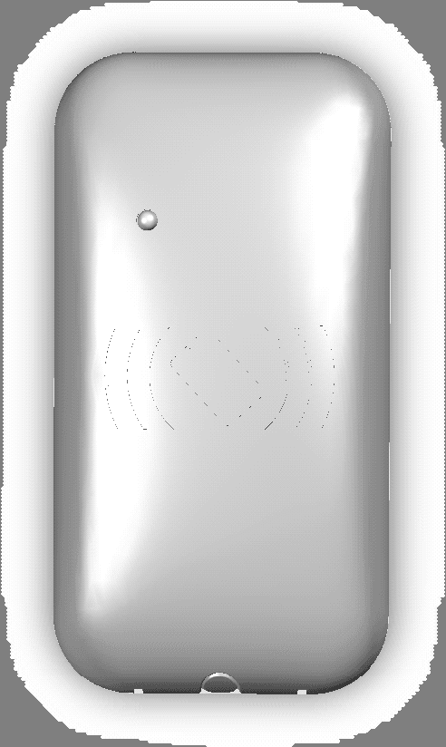
Click to zoom
Application Details
- Equipment Class
- DXT - Part 15 Low Power Transceiver, Rx Verified
- Date of Grant
- Aug 27, 2006
- Application Purpose
- Original Equipment
- Date of Application
- Aug 27, 2006
- Equipment Note
- Inductive Tag Reader
- Frequency Range
- 0.12500000 - 0.12500000
- Company
- Baltech AG
- Country
- Germany
Documents & Files
Document Text
Text extracted from the exhibit documents filed with the FCC. Open a document above to read the original.
Users Manual
Operation Manual 0056A01B-001 / ACCESS45-HIDP-5-232-LB-EQUITRAC REVISION 1.0, 2006-08-06 The ACCESS45-5-232-HIDP-LB is a RFID Read-/Write-Device (short: reader) which is compatible to all HID Prox cards. It provides a serial interface RS232 to output or exchange data with a host computer (typically an Equitrac Page Counter Unit, a printer or a copy machine) and a 125 kHz inductive interface to provide power to and exchange data with the HID Prox card (or other available form-factors such as tags, key-fobs). The host computer can control a bi-colour LED and a beeper to interface with the user. Mounting and Connection The reader generates a magnetic field with the frequency of 125 kHz which is influenced by any electrically conductive material in close proximity to the device. When mounting the unit, a distance to any such material of minimum 10 cm is required to ensure that there will be no significant degradation of the performance in terms of read range and reliability. Mounting the unit directly to metal would result in a severe reduction of read range down to zero functionality. Care should be taken when testing the device after mounting at a problematic environment: Read ranges and performance vary from card to card and very much from card to tag or key-fob. When mounting multiple readers, the distance between readers should be minimum 1m to avoid degradation of performance due to interference. Computer screens or other electronic equipment can also generate noise levels in close neighbourhood which may influence the RF-interface of the reader. Please try different mounting locations in case RF performance is reduced after mounting the device at its intended position. To connect the device to an Equitrac PageCounter, printer or copy machine, please make sure the host system provides an 8-pin Mini-DIN socket intended for connection of the reader. Alternatively, the reader can be connected to any serial RS232-interface by using a converter connector from 8-pin Mini-DIN female to D-Sub 9 female and suitable connection for a power supply. In case the LED and Beeper control lines should be operated, suitable control can be applied according to the below given specifications. Operation Whenever the device is connected to a proper power supply, it will switch on the internal antenna and periodically scan for a card. Once a card has been detected, the card number is read, the data converted and sent to the host system through the serial interface. To enable the device to read cards, tags and key-fobs successfully, they should be placed centred above the reader. Technical Data DC Electrical Characteristics Symbol Parameter Condition Min Typ Max Units Vdd Supply Voltage 4.75 5 5.5 VDC Idd Supply current 200 mA Idd1 Peak Supply current Inrush 450 mA Vih Input high voltage 3.3 Vdd+0.3 V Vil Input low voltage -0.3 0.8 V Ii Input leakage current 300 uA Additional requirements for the supply voltage: Vripple = 50mVpp max. RF Characteristics Operating frequency: 125 kHz Data transmission modulation reader to card: AM Data transmission modulation card to reader: AM Pinout 8-Pin Mini-DIN plug and Signal Descriptions Pin Name Type Description 1 PWR Power 5V Power Supply 2 TXD Output RS232-data from reader 3 RXD Input RS232-data to reader 4 RED Input LED red (when LED green is low) 5 GRN Inpur LED green (when LED red is low) 6 - - Not connected 7 /SPKR Input Speaker enable (active low) 8 GND Power Signal and Power Ground Serial Interface The TXD/RXD signals are compatible with RS-232 level signals. The interface operates at 2400 baud, no parity, 8 data bits, 1 stop bit. Upon detection of a valid card swipe, the reader outputs the card number in ASCII format. Temperature Operating temperature range: 0...35°C Storage temperature range: -20...+60°C Thermal shock: 30°C/min maximum dT/dt Humidity Operating: 20% to 80% relative humidity; non condensing Non-operating: 10% to 90% relative humidity; non condensing FCC Any changes or modifications not expressly approved by the party responsible for compliance could void the user's authority to operate the equipment.
Cover Letter(s)
Federal Communications Commission 445 12 th Street SW Washington, DC 20554 USA Request for Confidentiality in accordance with CFR 0.457 and 0.459 25 August 2006 EMCCert DR. RAŠEK - Certification Institute - Boelwiese 5 D-91320 Ebermannstadt RE: Certification Application FCC ID: OKY1005600151A01B Please be advised that the following information is to be held confidential on behalf of Baltech AG: • Schematics • Parts List • Block Diagram • Technical Description The application contains technical information which Baltech AG deems to be trade secrets and proprietary. If made public, the information might be used to the disadvantage of the applicant in the market place. Thank you for your attention to this matter.
Internal Photos
FCC ID OKY1005600151A01B FCC ID OKY1005600151A01B
Test Report
Senton GmbH Aeussere Fruehlingstrasse 45 D-94315 Straubing Note: The test data of this report is related only to the individual item which has been tested. This report shall not be reproduced except in full extent without the written approval of the testing laboratory. Test Report No. 50235-060611-2 (Edition 1) Page 1 of 40 Pages Straubing, August 25, 2006 T E S T - R E P O R T No. 50235-060611-2 (Edition 1) for ACCESS45-HIDP-5-232-LB-EQUITRAC Inductive Tag Reader Applicant: BALTECH AG Test Specifications: FCC Code of Federal Regulations, CFR 47, Part 15, Sections 15.205, 15.207 and 15.209 Industry Canada Radio Standards Specifications RSS-Gen Issue 1, Section 7.2.2 and RSS-210 Issue 6, Sections 2.2, 2.6 (Category I Equipment) Senton GmbH Aeussere Fruehlingstrasse 45 D-94315 Straubing Test Report No. 50235-060611-2 (Edition 1) Page 2 of 40 Pages Table of Contents 1 Description of the Equipment Under Test (EUT)......................................................... 3 2 Administrative Data..................................................................................................... 4 3 Identification of the Test Laboratory............................................................................ 5 4 Summary .................................................................................................................... 6 5 Operation Mode and Configuration of EUT ................................................................. 7 6 Measurement Procedures........................................................................................... 8 6.1 Bandwidth Measurements .................................................................................... 8 6.2 Conducted AC Powerline Emission.................................................................... 10 6.3 Radiated Emission Measurement 9 kHz to 30 MHz ........................................... 12 6.4 Radiated Emission in Fully or Semi Anechoic Room .......................................... 14 6.5 Radiated Emission at Open Field Test Site ........................................................ 16 7 Photographs Taken During Testing .......................................................................... 17 8 Test Results .............................................................................................................. 25 8.1 Occupied Bandwidth........................................................................................... 27 8.2 Designation of Emissions ................................................................................... 32 8.3 Restricted Bands of Operation............................................................................ 33 8.4 Conducted Powerline Emission Measurement 150 kHz to 30 MHz ................... 34 8.5 Radiated Emission Measurement 9 kHz to 30 MHz .......................................... 35 8.6 Radiated Emission Measurement 30 MHz to 1 GHz ......................................... 36 8.7 Exposure of Humans to RF Fields...................................................................... 37 9 Referenced Regulations ........................................................................................... 39 10 Charts taken during testing ....................................................................................... 40 Senton GmbH Aeussere Fruehlingstrasse 45 D-94315 Straubing Test Report No. 50235-060611-2 (Edition 1) Page 3 of 40 Pages 1 Description of the Equipment Under Test (EUT) General data of EUT Type designation 1 : ACCESS45-HIDP-5-232-LB-EQUITRAC Parts 2 : --- Serial number(s): Sample no. 1 Manufacturer: BALTECH AG Type of equipment: Inductive Tag Reader Version: As delivered FCC ID: OKY1005600151A01B Additional parts/accessories: with tag "HID Prox Card II" Technical data of EUT Application frequency range: Not applicable Frequency range: 125 kHz Operating frequency: 125 kHz Type of modulation: Amplitude Modulation (AM) Number of RF-channels: 1 Channel spacing: Not applicable Designation of emissions 3 : 20K0A1D Type of antenna: Integrated loop antenna Size/length of antenna: Rectangle: 37 mm x 20 mm Connection of antenna: detachable not detachable Type of power supply: DC supply Specifications for power supply: nominal voltage: 5.00 V minimum voltage: 4.25 V maximum voltage: 5.50 V 1 Type designation of the system if EUT consists of more than one part. 2 Type designations of the parts of the system, if applicable. 3 Also known as "Class of Emission". Senton GmbH Aeussere Fruehlingstrasse 45 D-94315 Straubing Test Report No. 50235-060611-2 (Edition 1) Page 4 of 40 Pages 2 Administrative Data Application details Applicant (full address): BALTECH AG Lilienthalstrasse 27 D-85399 Hallbergmoos Germany Contact person: Mr. Jürgen Rösch Contract identification: --- Receipt of EUT: August 1, 2006 Date(s) of test: August 8 and August 21 to 24, 2006 Note(s): --- Report details Report number: 50235-060611-2 Edition: 1 Issue date: August 25, 2006 Senton GmbH Aeussere Fruehlingstrasse 45 D-94315 Straubing Test Report No. 50235-060611-2 (Edition 1) Page 5 of 40 Pages 3 Identification of the Test Laboratory Details of the Test Laboratory Company name: Senton GmbH EMI/EMC Test Center Address: Aeussere Fruehlingstrasse 45 D-94315 Straubing Germany Laboratory accreditation: DAR-Registration No. DAT-P-171/94-02 FCC test site registration number 90926 Industry Canada test site registration: IC 3050 Contact person: Mr. Johann Roidt Phone: (+49) (0)9421 5522-0 Fax: (+49) (0)9421 5522-99 Senton GmbH Aeussere Fruehlingstrasse 45 D-94315 Straubing Test Report No. 50235-060611-2 (Edition 1) Page 6 of 40 Pages 4 Summary Summary of test results The tested sample complies with the requirements set forth in the Code of Federal Regulations CFR 47, Part 15, Sections 15.205, 15.207 and 15.209 of the Federal Communication Commission (FCC) and the Radio Standards Specifications RSS-Gen Issue 1, Section 7.2.2 and RSS-210 Issue 6, Sections 2.2, 2.6 (Category I Equipment) …
Text truncated - open the document above for the full version.
Test Setup Photos
Senton GmbH Aeussere Fruehlingstrasse 45 D-94315 Straubing Test Report No. 50235-060611-2 (Edition 1) Page 18 of 40 Pages Test setup for conducted AC powerline emission measurement Senton GmbH Aeussere Fruehlingstrasse 45 D-94315 Straubing Test Report No. 50235-060611-2 (Edition 1) Page 19 of 40 Pages Test setup for conducted AC powerline emission measurement - continued - Senton GmbH Aeussere Fruehlingstrasse 45 D-94315 Straubing Test Report No. 50235-060611-2 (Edition 1) Page 20 of 40 Pages Test setup for radiated emission measurement 9 kHz – 30 MHz (prescan in fully anechoic room) Senton GmbH Aeussere Fruehlingstrasse 45 D-94315 Straubing Test Report No. 50235-060611-2 (Edition 1) Page 21 of 40 Pages Test setup for radiated emission measurement 9 kHz – 30 MHz Senton GmbH Aeussere Fruehlingstrasse 45 D-94315 Straubing Test Report No. 50235-060611-2 (Edition 1) Page 22 of 40 Pages Test setup for radiated emission measurement (prescan in fully anechoic room) Senton GmbH Aeussere Fruehlingstrasse 45 D-94315 Straubing Test Report No. 50235-060611-2 (Edition 1) Page 23 of 40 Pages Test setup for radiated emission measurement (open field test site) Senton GmbH Aeussere Fruehlingstrasse 45 D-94315 Straubing Test Report No. 50235-060611-2 (Edition 1) Page 24 of 40 Pages Test setup for radiated emission measurement (open field test site) - continued -
Contact Information
Applicant
Juergen Roesch(President)
Test Firm
TUV SUD Product Service GmbH PS-EMC-STRRainer Heller
Technical Specifications
| # | Rule Parts | Frequency Range | Power Output |
|---|---|---|---|
| 1 | 15C | 0.125 MHz - 0.125 MHz | - |
Other Applications from Baltech AG
OKY12117601A01A
Jan 15, 2023RFID Card Reader
Equipment Class
DXX - Part 15 Low Power Communication Device Transmitter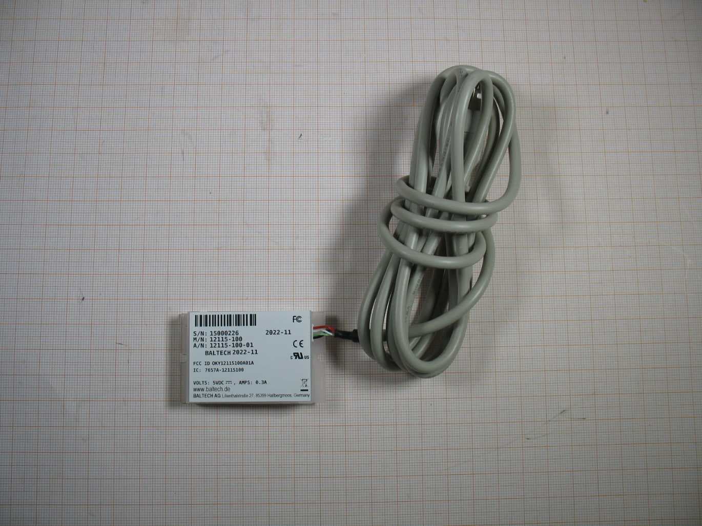
OKY12115100A01A
Jan 04, 2023RFID Card Reader
Equipment Class
DXX - Part 15 Low Power Communication Device Transmitter
OKY10115100A06A
Jul 26, 2021RFID Card Reader
Equipment Class
DXX - Part 15 Low Power Communication Device Transmitter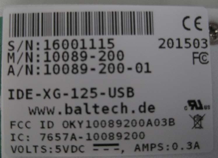
OKY10089200A03B
May 05, 2015IDE-XG-125-USB
Equipment Class
DXX - Part 15 Low Power Communication Device Transmitter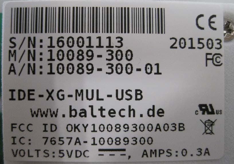
OKY10089300A03B
May 05, 2015IDE-XG-MUL-USB
Equipment Class
DXX - Part 15 Low Power Communication Device Transmitter