OKY10090100A02BSHARK M/ID-engine-M
Baltech AG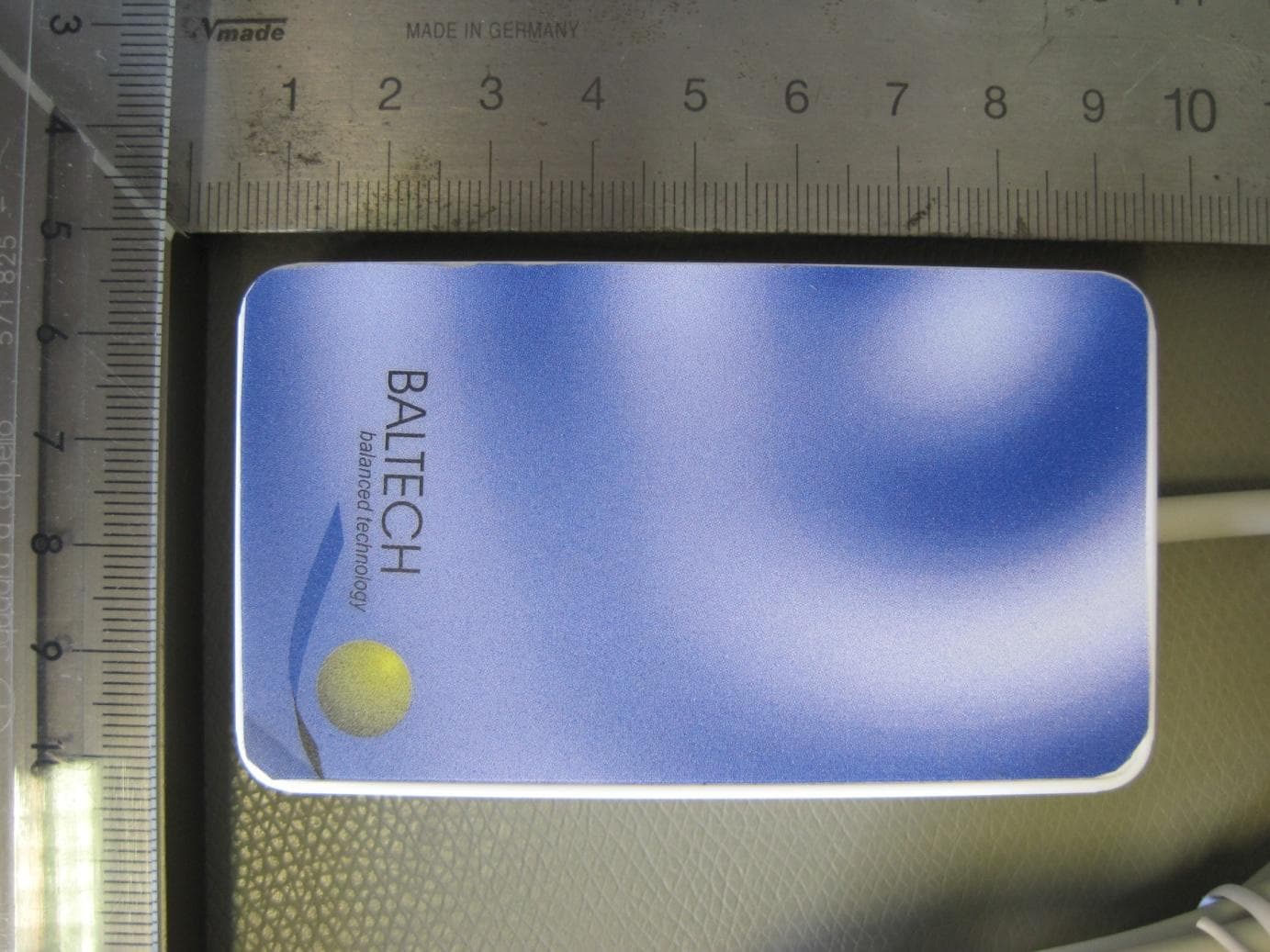
Click to zoom
Application Details
- Equipment Class
- DXX - Part 15 Low Power Communication Device Transmitter
- Date of Grant
- Dec 09, 2013
- Application Purpose
- Original Equipment
- Date of Application
- Dec 09, 2013
- Equipment Note
- SHARK M/ID-engine-M
- Frequency Range
- 13.56000000 - 13.56000000
- Company
- Baltech AG
- Country
- Germany
Documents & Files
Document Text
Text extracted from the exhibit documents filed with the FCC. Open a document above to read the original.
Users Manual
Operation Manual RFID Reader “IDE-PAD-MX-M1415” REVISION 2.0, 2013-12-04 Confidential information, all rights reserved. BALTECH AG Lilienthalstraße 27 85399 Hallbergmoos Germany Phone: +49 (811) 99 88 1- 0 FAX: +49 (811) 99 88 1- 11 e-mail: [email protected] http://www.baltech.de/ - 1 - Covered Variants: 10090-100 10090-1x 1 -y 1 Shark M-1415 IDE-PAD-MX-M1415 1 “x“ and “y”shall represent any numerical number. - 2 - Introduction The “Shark M-1415” is a desktop contactless smart card USB reader and writer that supports Mifare, ISO 14443A/B and ISO 15693 standard compliant cards and all cards compliant to these standards. Based on BALTECH’s core technology it provides support of the latest smartcard technologies, encryption and security features. Mounting and Connection The reader generates a magnetic field at 13.56MHz frequency which could be influenced by any electrically conductive material close to the device. To ensure good performances and functionalities in terms of read range and reliability a minimum distance of 10cm from such materials is required. Mounting the unit directly to metal would result in a severe reduction of read range down to zero functionality. Care should be taken when testing the device after mounting at a problematic environment: Read ranges and performance vary from card to card and very much from card to tag or key-fob. When mounting multiple readers, the distance between readers should be minimum 0.5 m in order to avoid degradation of performance due to interference. To connect the device to a host system (a printer or a PC), please make sure that the system provides an USB socket intended for connection of the reader. Operation Whenever the device is connected to a proper power supply, it will switch on the internal antenna and periodically scan for a card. Once a card has been detected, the card number is read, the data converted and sent to the host system through the USB Interface. To enable the device to read cards, tags and key-fobs successfully, they should be placed centred above the reader. - 3 - Technical Features Parameters Descriptions RF-Characteristics Operated Frequencies 13.56MHz Data transmission modulation reader to card: ASK Data transmission modulation card to reader: AM/Load modulation Interfaces Host USB: Full speed 2.0 Contactless Supported standards: ISO14443 A & B, ISO15693, Communication speed ISO14443A/B: Baud rate up to 424kBaud Reading distance: Up to 9 cm- depending on the tags. Human LEDs, Buzzer Power Supply [V DC ] USB bus powered: 5 (±5%) Consumption [W] Up to 1.0 / 0.75 typ. Temperature Operating [°C] -20 to +65 Storage [°C] -25 to +85 Humidity Operating[%] 20 to 80 relative humidity; non condensing Non Operating [%] 10 to 90 relative humidity; non condensing Pinout 4-Pin USB-A plug and Signal Descriptions Pin Name Type Description 1 PWR Power 5V Power Supply 2 D- Output USB-Data inverted 3 D+ Input USB-data 4 GND Power Signal and Power Ground - 4 - General regulatory requirements FCC Compliance Statement: This device complies with Part 15 of the FCC rules. The product FCC ID is OKY10090100A02B. The operation is subject to the following two conditions: (1) This device may not cause harmful interference. (2) This device must accept any interference received, including interference that may cause undesired operation. Caution: Any changes or modifications not expressly approved by the party responsible for compliance could void the user's authority to operate the equipment. This equipment has been tested and found to comply with the limits for a Class B digital device, pursuant to Part 15 of the FCC Rules. These limits are designed to provide reasonable protection against harmful interference in a residential installation. This equipment generates, uses and can radiate radio frequency energy and, if not installed and used in accordance with the instructions, may cause harmful interference to radio communications. However, there is no guarantee that interference will not occur in a particular installation. If this equipment does cause harmful interference to radio or television reception, which can be determined by turning the equipment off and on, the user is encouraged to try to correct the interference by one or more of the following measures: -- Reorient or relocate the receiving antenna. -- Increase the separation between the equipment and receiver. -- Connect the equipment into an outlet on a circuit different from that to which the receiver is connected. -- Consult the dealer or an experienced radio/TV technician for help. Canada Statement: This device complies with Industry Canada licence-exempt RSS standard(s). The product IC ID is “7657A-10090100”. Operation is subject to the following two conditions: (1) This device may not cause harmful interference, and (2) this device must accept any interference received, including interference that may cause undesired operation. Le présent appareil est conforme aux CNR d'Industrie Canada applicables aux appareils radio exempts de licence. L'exploitation est autorisée aux deux conditions suivantes: (1) l'appareil ne doit pas produire de brouillage, et (2) l'utilisateur de l'appareil doit accepter tout brouillage radioélectrique subi, même si le brouillage est susceptible d'en compromettre le fonctionnement.
External Photos
External Pictures for “10090-100” FCC ID : OKY10090100A02B IC ID: 7657A-10090100 Covered Variants: 10090-100, 10090-1X 1 -Y 1 This product is available in different housing types : “IDE-PAD-MX “ & “SharkM” “IDE –PAD-MX “ Housing Top 2 1 “x“ and “y” shall represent any numerical number 2 The front cover here is just used for purposes of illustration. The graphic is available in different designs. “IDE –PAD-MX” Housing Bottom Dimensions: SharkM Housing Top SharkM Housing Bottom: Dimensions:
ID Label/Location Info
Label Location for Model #:10090-100 Label Location for Model #:10090-110
Internal Photos
Internal Pictures for “10090-100” FCC ID : OKY10090100A02B IC ID: 7657A-10090100 Covered Variants: 10090-100, 10090-1X 1 -Y 1 The product is available in different housing types : “IDE-PAD-MX “ & “SharkM” Top 1 “x“ and “y” shall represent any numerical number Bottom Top with optional integrated SAM Bottom Removed „IDE-PAD-MX” back cover: Top: Bottom: Removed “SharkM” back cover: Top: Bottom
Test Report
Note: The test data of this report is related only to the individual item which has been tested. This report shall not be reproduced except in full extent without the written approval of the testing laboratory. Trade Register Munich HRB 85742 VAT ID No. DE129484267 Information pursuant to Section 2(1) DL-InfoV (Germany) at www.tuev-sued.com/imprint Supervisory Board: Dirk Eilers Management: Robert Kees Dr. Jens Butenandt Phone: +49 9421 55 22-0 Fax: +49 9421 55 22-99 www.tuev-sued.de TÜV SÜD Product Service GmbH Äußere Frühlingstraße 45 94315 Straubing Germany Prüfbericht / Test Report Nr. / No. 59583-24398 (Edition 2) Applicant: Baltech AG Type of equipment: RFID-Reader Type designation: ID-engine-M Order No.: E-Mail 21 May 2013 Test standards: FCC Code of Federal Regulations, CFR 47, Part 15, Sections 15.205, 15.207, 15.215 and 15.225 Industry Canada Radio Standards Specifications RSS-GEN Issue 3, Sections 7.2.2, 7.2.4 and 7.2.5 and RSS-210 Issue 8, Section A2.6 (Category I Equipment) May 31, 2013 Page 1 of 57 TÜV SÜD Product Service GmbH Äußere Frühlingstraße 45 94315 Straubing Germany Phone: +49 9421 5522-0 Fax: +49 9421 5522-99 Web: www.tuev-sued.de Test Report No. 59583-24398 (Edition 2) Page 2 of 57 Pages Table of Contents 1 Description of the Equipment Under Test (EUT) ............................................................ 3 2 Administrative Data ........................................................................................................ 5 3 Identification of the Test Laboratory ............................................................................... 6 4 Summary ........................................................................................................................ 7 5 Operation Mode and Configuration of EUT .................................................................... 8 6 Measurement Procedures .............................................................................................. 9 6.1 Bandwidth Measurements ....................................................................................... 9 6.2 Conducted AC Powerline Emission ....................................................................... 11 6.3 Radiated Emission Measurement 9 kHz to 30 MHz ............................................... 13 6.4 Radiated Emission in Fully or Semi Anechoic Room ............................................. 15 6.5 Radiated Emission at Alternative Test Site ............................................................ 17 6.6 Carrier Frequency Stability ..................................................................................... 19 7 Photographs Taken During Testing .............................................................................. 21 8 Test Results ................................................................................................................. 26 8.1 Occupied Bandwidth .............................................................................................. 28 8.2 Bandwidth of the Emission..................................................................................... 32 8.3 Designation of Emissions ....................................................................................... 34 8.4 Conducted Powerline Emission Measurement 150 kHz to 30 MHz ...................... 35 8.5 Spectrum Mask ...................................................................................................... 38 8.6 Radiated Emission Measurement 9 kHz to 30 MHz .............................................. 40 8.7 Radiated Emission Measurement 30 MHz to 1 GHz ............................................. 45 8.8 Carrier Frequency Stability ..................................................................................... 49 8.9 Exposure of Humans to RF Fields ......................................................................... 52 9 Referenced Regulations ............................................................................................... 54 10 Test Equipment List with Calibration Data ................................................................... 56 11 Revision History ........................................................................................................... 57 TÜV SÜD Product Service GmbH Äußere Frühlingstraße 45 94315 Straubing Germany Phone: +49 9421 5522-0 Fax: +49 9421 5522-99 Web: www.tuev-sued.de Test Report No. 59583-24398 (Edition 2) Page 3 of 57 Pages 1 Description of the Equipment Under Test (EUT) General data of EUT Type designation 1 : ID-engine-M Variants covered by this report 2 : HW Revision / Model Number Functionality 10090-3X-Y 10090-300 10090-310 10090-320 10090-330 10090-340 10090- 350 13,56MHz & 125kHz 10090-1X-Y 10090-100 10090-110 10090-120 10090-130 10090-140 10090- 150 13,56MHz only 10090-2X-Y 10090-200 125kHz only Serial number(s): Prototype Manufacturer: Baltech AG Type of equipment: RFID-Reader Version: As delivered FCC ID: N/A Industry Canada ID: N/A Additional parts/accessories: N/A Technical data of EUT Application frequency range: - 0.009 – 0.490 MHz - 13.111 – 14.01 MHz Frequency range: Operating frequency: 125 kHz, 13.56 MHz 1 Type designation of the system if EUT consists of more than one part. 2 Type designations of the parts of the system, if applicable. TÜV SÜD Product Service GmbH Äußere Frühlingstraße 45 94315 Straubing Germany Phone: +49 9421 5522-0 Fax: +49 9421 5522-99 Web: www.tuev-sued.de Test Report No. 59583-24398 (Edition 2) Page 4 of 57 Pages Type of modulation: ASK Number of RF-channels: 2 Channel spacing: N/A Designation of emissions 3 : Type of antenna: Integrated Size/length of antenna: Connection of antenna: detachable not detachable Type of power supply: DC supply Specifications for power supply: nominal voltage: 5.0 V minimum voltage: 4.75 V maximum voltage: 5.25 V nominal frequency: DC Hz 3 Also known as "Class of Emission". TÜV SÜD Product Service GmbH Äußere Frühlingstraße 45 94315 Straubing Germany P…
Text truncated - open the document above for the full version.
Test Setup Photos
TÜV SÜD Product Service GmbH Äußere Frühlingstraße 45 94315 Straubing Germany Phone: +49 9421 5522-0 Fax: +49 9421 5522-99 Web: www.tuev-sued.de Test Report No. 59583-24398 (Edition 2) Page 22 of 57 Pages Test setup for conducted AC powerline emission measurement TÜV SÜD Product Service GmbH Äußere Frühlingstraße 45 94315 Straubing Germany Phone: +49 9421 5522-0 Fax: +49 9421 5522-99 Web: www.tuev-sued.de Test Report No. 59583-24398 (Edition 2) Page 23 of 57 Pages Test setup for radiated emission measurement 9 kHz – 30 MHz TÜV SÜD Product Service GmbH Äußere Frühlingstraße 45 94315 Straubing Germany Phone: +49 9421 5522-0 Fax: +49 9421 5522-99 Web: www.tuev-sued.de Test Report No. 59583-24398 (Edition 2) Page 24 of 57 Pages Test setup for radiated emission measurement (alternate test site) TÜV SÜD Product Service GmbH Äußere Frühlingstraße 45 94315 Straubing Germany Phone: +49 9421 5522-0 Fax: +49 9421 5522-99 Web: www.tuev-sued.de Test Report No. 59583-24398 (Edition 2) Page 25 of 57 Pages Test setup for carrier frequency stability measurement
Contact Information
Applicant
Juergen Roesch(President)
Test Firm
TUV SUD Product Service GmbH PS-EMC-STRRainer Heller
Technical Specifications
| # | Rule Parts | Frequency Range | Power Output |
|---|---|---|---|
| 1 | 15C | 13.56 MHz - 13.56 MHz | - |
Other Applications from Baltech AG
OKY12117601A01A
Jan 15, 2023RFID Card Reader
Equipment Class
DXX - Part 15 Low Power Communication Device Transmitter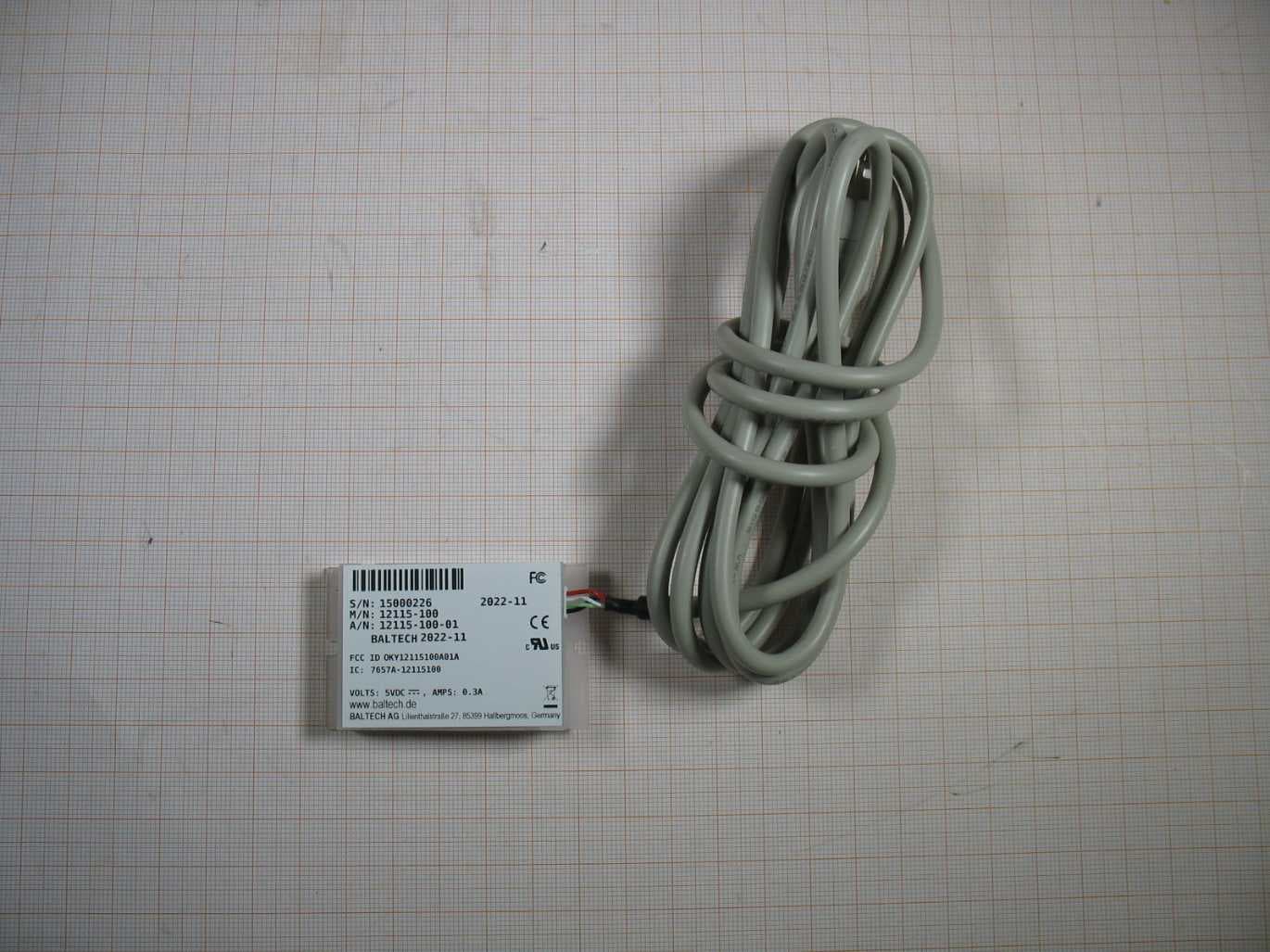
OKY12115100A01A
Jan 04, 2023RFID Card Reader
Equipment Class
DXX - Part 15 Low Power Communication Device Transmitter
OKY10115100A06A
Jul 26, 2021RFID Card Reader
Equipment Class
DXX - Part 15 Low Power Communication Device Transmitter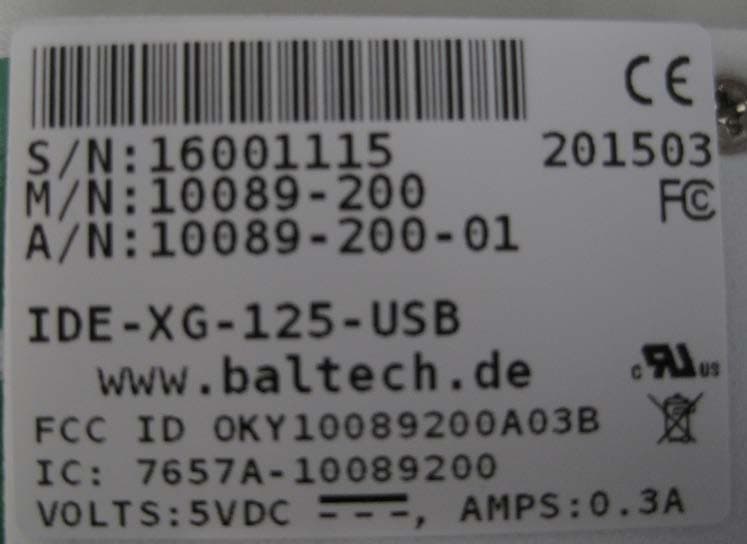
OKY10089200A03B
May 05, 2015IDE-XG-125-USB
Equipment Class
DXX - Part 15 Low Power Communication Device Transmitter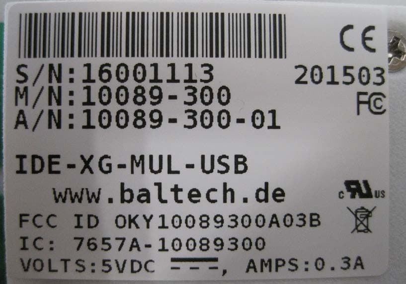
OKY10089300A03B
May 05, 2015IDE-XG-MUL-USB
Equipment Class
DXX - Part 15 Low Power Communication Device Transmitter