OKY1053300101A03CInductive Tag Reader Module
Baltech AG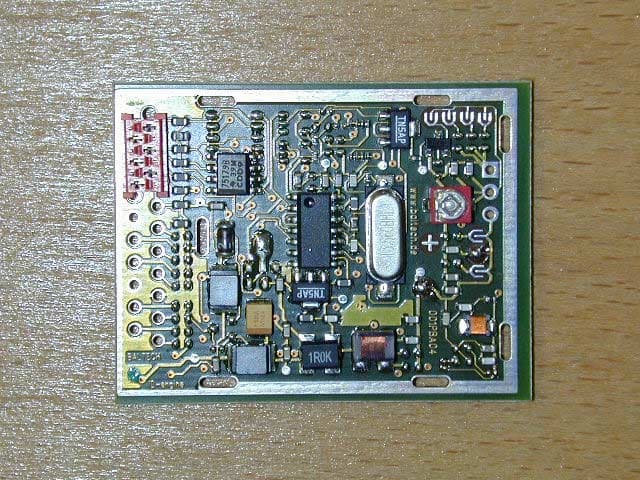
Click to zoom
Application Details
- Equipment Class
- DXX - Part 15 Low Power Communication Device Transmitter
- Date of Grant
- Mar 12, 2007
- Application Purpose
- Original Equipment
- Date of Application
- Mar 12, 2007
- Equipment Note
- Inductive Tag Reader Module
- Frequency Range
- 13.56000000 - 13.56000000
- Company
- Baltech AG
- Country
- Germany
Documents & Files
Document Text
Text extracted from the exhibit documents filed with the FCC. Open a document above to read the original.
Users Manual
0533A03C-001_manualR10.doc Page 1 of 2 Operation Manual BSM2-100 / 0533A03C-001 with 0001A04C and 0505A01A REVISION 1.0, 2006-11-17 The BSM2-100 is a RFID Read-/Write-Device (short: reader) which is compatible to all mifare® contactless smartcards. It provides a serial interface RS232 to output or exchange data with a host computer and a 13.56MHz inductive interface to provide power to and exchange data with the Mifare/ISO compliant card (or other available form-factors such as tags, key-fobs). Mounting and Connection The reader generates a magnetic field with the frequency of 13.56MHz which is influenced by any electrically conductive material in close proximity to the device. When mounting the antenna, a distance to any such material of minimum 10 cm is required to ensure that there will be no significant degradation of the performance in terms of read range and reliability. Mounting the antenna directly to metal would result in a severe reduction of read range down to zero functionality. Care should be taken when testing the device after mounting at a problematic environment: Read ranges and performance vary from card to card and very much between card and Tag’s or key-fob. When mounting multiple readers, the distance between readers should be minimum 1 m to avoid degradation of performance due to interference between the antennas. To connect the device to a host computer, any serial RS232-interface (COM-port) can be used. There is a special cable required to connect to the AMP MicroMatch 20-Pole connector which provides the communication and power supply connections. Operation When the device is connected to a proper power supply, it will perform some initialization routines and is then under control of the host system. The host software can initiate card scan cycles and, after a card has been detected, perform read and write operations to the card memory. Technical Data DC Electrical Characteristics Symbol Parameter Condition Min Typ Max Units Vdd Supply Voltage 4.75 5 5.5 VDC Idd Supply current 450 mA Idd1 Peak Supply current Inrush 650 mA Power supply voltage to be measured at BSM2-100 connector (NOT including voltage drop over connection cable). Additional requirements for the supply voltage: Vripple = 50mVpp max. 0533A03C-001_manualR10.doc Page 2 of 2 RF Characteristics Operating frequency: 13.56 MHz Data transmission modulation reader to card: AM 100% Data transmission modulation card to reader: AM/load modulation Pinout 20-Pin AMP MicroMatch Connector BSM2-100<->Host Pin Name Type Description 1,2 PWR Power 5V Power Supply 3,4, 20 GND Power Signal and Power Ground 5 TXD Output RS232-data from reader 6 RXD Input RS232-data to reader 7-19 - - Not connected 6-Pin AMP MicroMatch Connector Module 0533A03C-001 <-> 0001A04C To be connected 1:1 with a flatband ribbon cable AWG26-28, length 30cm (1’). Serial Interface The TXD/RXD signals are compatible with RS-232 level signals. The interface operates at 19200 baud, no parity, 8 data bits, 1 stop bit. The communication protocol used is the T3964R protocol. Temperature Operating temperature range: 0...35°C Storage temperature range: -20...+60°C Thermal shock: 30°C/min maximum dT/dt Humidity Operating: 20% to 80% relative humidity; non condensing Non-operating: 10% to 90% relative humidity; non-condensing ® mifare is a registered trademark of Philips Semiconductors, The Netherlands. ® mifare is a registered trademark of Philips Semiconductors, The Netherlands.
Cover Letter(s)
BALTECH balanced technology BALTECH Aktiengesellschaft für elektronische Identifikationssysteme Sitz: Hallbergmoos. Amtsgericht München, HRB 115215 Vorsitzender des Aufsichtsrats: Eva Zeising Vorstand: Jürgen Rösch (Vorsitzender), Martina Schuster-Rösch Postanschrift: Lilienthalstrasse 27, 85399 Hallbergmoos Telefon: 08 11 / 99 88 1-0; Telefax: 08 11 / 99 88 1-11 USt.-Id.-Nr.: Bankverbindung: DE185441242 Dresdner Bank Freising, Kto.: 9 253 221 00 BLZ: 700 800 00 BALTECH AG Lilienthalstrasse 27 Hallbergmoos 85399 GERMANY Hallbergmoos, Oct. 4th, 2006 Date Juergen ROESCH President PHOENIX TEST-LAB GmbH Product Certification Königswinkel 10 D 32825 Blomberg To Whom It May Concern: Please be advised that BALTECH AG authorizes Senton GmbH to act on our behalf, until otherwise notified, for applications submitted to PHOENIX TEST-LAB GmbH (PTL). We certify that we are not subject to denial of federal benefits, that includes FCC benefits, pursuant to Section 5301 of the Anti-Drug Abuse ACT of 1988, U.S.C.862. Further, no party, as defined in 47 CFR 1.2002 (b), to the application is subject to denial of federal benefits, that includes FCC benefits. Thank you for your attention to this matter.
Cover Letter(s)
Dirk Brandhorst/blom/DE/Phoeni x Contact 13.03.2007 15:07 An Kopie Blindkopie Thema WG: Response to Inquiry to FCC (Tracking Number 754306) Generic Office of Engineering Technology <[email protected] > 09.03.2007 17:32 An Kopie Thema Response to Inquiry to FCC (Tracking Number 754306) Inquiry: Dear FCC, We have just received an application for a LIMITED MODULAR APPROVAL of an RFID-Transceiver Module subject to §15.225 (Operation within the band 13.110-14.010 MHz.) After reviewing the technical documentation we figured out, that the RFID read/write device consists of two separate electronic modules: Module A with RF-Amplifier, - receiver and antenna Module B with host interface, power stabilization, RF Modulation and decoding -> Both modules are connected via flatband ribbon cable. We think that this configuration can be certified as LMA, when the Grantee can demonstrate that he will retain control over the final installation of the device, such that compliance of the end product is assured, as integration will be performed by the Grantee himself. Module A will be labled with the appropriate FCC ID. Grant Note will limit integration of Module A only in combination with tested Module B as documented in the filing and integration is limited to the Grantee. Please kindly confirm or advise. Response: We agree that the described configuration can be certified as a LMA, when the Grantee can demonstrate that he will retain control over the final installation of the device. Also, we agree with the proposed labeling method for Module A to be labled with the appropriate FCC ID, and that a grant note will be added to limit integration of Module A, only in combination with tested Module B, as documented in the filing and integration is limited to the Grantee. Do not reply to this message. Please select the Reply to an Inquiry Response link from the OET Inquiry System to add any additional information pertaining to this inquiry.
Cover Letter(s)
EMV-Prüfzentrum EMI/EMC-Testcenter Coordinates: Äussere Frühlingstrasse 45 y D-94315 Straubing Telefon (0 94 21) 55 22-0 Telefax (0 94 21) 55 22-99 [email protected] y http://www.senton.de Senton GmbH y Äussere Frühlingstraße 45 y D-94315 Straubing PHOENIX TEST-LAB GmbH Koenigswinkel 10 D-32825 Blomberg Germany 26 February 2007 In reference to FCC ID OKY1053300101A03C Justification for Part 15 Unlicensed Modular Transmitter Approval according to DA 00-1407 1. Own RF Shielding Not complied, but subject to limited modular approval. The Grantee can demonstrate that it will retain control over the final installation of the device, such that compliance of the end product is assured. In such a case, an operating condition on the grant of equipment authorization for the module would state that the module is only approved for use when installed in devices produced by a specific manufacturer, typically the Grantee. 2. Buffered Modulation inputs Complied, no direct modulation input. Modulated signals will be buffered by microcontroller U1. 3. Own power supply regulation Complied, voltage regulated power supply on board, see schematic diagram 4. Antenna requirements Complied, unique antenna coupler employed 5. Test in stand-alone configuration Complied, see test report for details. Cable lengths typical to actual use. 6. Own FCC ID Complied, the exterior label will be "Contains FCC ID OKY1053300101A03C" Subject to limited modular approval 7. The Modular Transmitter must comply with any specific rule and the manufacturer must provide adequate instructions The EUT is compliant with all applicable FCC rules. Detail instructions are given in the User guide. 8. RF Exposure requirements Not applicable since the unit operates under section 15.225 of the FCC rules. The reference guide contains general installation and operation instructions. MPE evaluation not required. Johann Roidt Senton GmbH
Cover Letter(s)
Ersteller: U. Rodemeier Revision: 03 Erstelldatum: 03.08.01 Datum: 4.10.2006 Seite 1 von 1 Request for Confidentiality PHOENIX TESTLAB GmbH Date: 07 March 2007 Product Certification Königswinkel 10 D 32825 Blomberg RE: Certification Application FCC ID: OKY1053300101A03C Confidentiality Request Pursuant to Sections 0.457 and 0.459 of the Commission’s Rule, the applicant hereby requests confidential treatment of information accompanying this application as outlined below: • Schematics • Block Diagram • Parts List • Technical Description The above materials contain trade secrets and proprietary information not customarily released to the public. The public disclosure of these matters might be harmful to the applicant and provide unjustified benefits to its competitors. The applicant understands that pursuant to rule 0.457, disclosure od this application and all accompanying documentation will not be made before the date of the GRANT for this application ́. Thank you for your attention in this matter. Applicant’s Company : Senton GmbH address : Auessere Fruehlingstrasse 45, D-94315 Straubing Signature : Johann Roidt Job Title and Dept. : Technical Director
External Photos
FCC ID OKY1053300101A03C FCC ID OKY1053300101A03C FCC ID OKY1053300101A03C FCC ID OKY1053300101A03C FCC ID OKY1053300101A03C
External Photos
FCC ID OKY1053300101A03C FCC ID OKY1053300101A03C FCC ID OKY1053300101A03C FCC ID OKY1053300101A03C FCC ID OKY1053300101A03C FCC ID OKY1053300101A03C
External Photos
FCC ID OKY1053300101A03C FCC ID OKY1053300101A03C
ID Label/Location Info
FCC ID OKY1053300101A03C
Internal Photos
FCC ID OKY1053300101A03C FCC ID OKY1053300101A03C FCC ID OKY1053300101A03C FCC ID OKY1053300101A03C FCC ID OKY1053300101A03C
Internal Photos
FCC ID OKY1053300101A03C FCC ID OKY1053300101A03C FCC ID OKY1053300101A03C FCC ID OKY1053300101A03C FCC ID OKY1053300101A03C FCC ID OKY1053300101A03C
Internal Photos
FCC ID OKY1053300101A03C FCC ID OKY1053300101A03C
Test Report
Senton GmbH Aeussere Fruehlingstrasse 45 D-94315 Straubing Note: The test data of this report is related only to the individual item which has been tested. This report shall not be reproduced except in full extent without the written approval of the testing laboratory. Test Report No. 50235-060954 (Edition 2) Page 1 of 49 Pages Straubing, 08 March 2007 T E S T - R E P O R T No. 50235-060954 (Edition 2) for BSM2-100 RFID Tag Reader Module Applicant: BALTECH AG Test Specifications: FCC Code of Federal Regulations, CFR 47, Part 15, Sections 15.205, 15.207, 15.215 and 15.225 Industry Canada Radio Standards Specifications RSS-Gen Issue 1, Section 7.2.2 and RSS-210 Issue 6, Sections 2.2, 2.6, A2.6 (Category I Equipment) Senton GmbH Aeussere Fruehlingstrasse 45 D-94315 Straubing Test Report No. 50235-060954 (Edition 2) Page 2 of 49 Pages Table of Contents 1 Description of the Equipment Under Test (EUT) ........................................................ 3 2 Administrative Data..................................................................................................... 4 3 Identification of the Test Laboratory ........................................................................... 5 4 Summary .................................................................................................................... 6 5 Operation Mode and Configuration of EUT................................................................. 7 6 Measurement Procedures........................................................................................... 8 6.1 Bandwidth Measurements .................................................................................... 8 6.2 Radiated Emission Measurement 9 kHz to 30 MHz ............................................. 9 6.3 Conducted AC Powerline Emission .................................................................... 11 6.4 Radiated Emission in Fully or Semi Anechoic Room.......................................... 13 6.5 Radiated Emission at Open Field Test Site........................................................ 15 6.6 Carrier Frequency Stability ................................................................................. 16 7 Photographs Taken During Testing .......................................................................... 18 8 Test Results .............................................................................................................. 25 8.1 Occupied Bandwidth........................................................................................... 27 8.2 Bandwidth of the Emission ................................................................................. 31 8.3 Designation of Emissions ................................................................................... 33 8.4 Conducted Powerline Emission Measurement 150 kHz to 30 MHz................... 34 8.5 Spectrum Mask................................................................................................... 36 8.6 Radiated Emission Measurement 9 kHz to 30 MHz .......................................... 38 8.7 Radiated Emission Measurement 30 MHz to 1 GHz ......................................... 41 8.8 Carrier Frequency Stability ................................................................................. 43 8.9 Exposure of Humans to RF Fields...................................................................... 46 9 Referenced Regulations ........................................................................................... 48 10 Charts taken during testing ....................................................................................... 49 Senton GmbH Aeussere Fruehlingstrasse 45 D-94315 Straubing Test Report No. 50235-060954 (Edition 2) Page 3 of 49 Pages 1 Description of the Equipment Under Test (EUT) General data of EUT Type designation 1 : BSM2-100 Parts 2 : ANT505-2-0/50: 7971: Interface Board: 533PBA03 Serial number(s): 0533A03C Manufacturer: BALTECH AG Type of equipment: RFID Tag Reader Module Version: As delivered FCC ID: Additional parts/accessories: Technical data of EUT Application frequency range: 13.553 - 13.567 MHz Frequency range: 13.56 MHz Operating frequency: 13.56 MHz Type of modulation: AM Pulse train: Not applicable Pulse width: Not applicable Number of RF-channels: 1 Channel spacing: Not applicable Designation of emissions 3 : 10K0A1D Type of antenna: Integrated Size/length of antenna: 50 x 390 mm Connection of antenna: detachable not detachable Type of power supply: Internal DC supply Specifications for power supply: nominal voltage: 5.00 V minimum voltage: 4.25 V maximum voltage: 5.75 V 1 Type designation of the system if EUT consists of more than one part. 2 Type designations of the parts of the system, if applicable. 3 Also known as "Class of Emission". Senton GmbH Aeussere Fruehlingstrasse 45 D-94315 Straubing Test Report No. 50235-060954 (Edition 2) Page 4 of 49 Pages 2 Administrative Data Application details Applicant (full address): BALTECH AG Lilienthalstraße 27 85399 Hallbergmoos Contact person: Herr Jürgen Rösch Contract identification: Order 31 October 2006 Receipt of EUT: 3 November 2006 Date(s) of test: 7 to 8 November 2006 8 March 2007 Note(s): Report details Report number: 50235-060954 Edition: 2 Issue date: 08 March 2007 Senton GmbH Aeussere Fruehlingstrasse 45 D-94315 Straubing Test Report No. 50235-060954 (Edition 2) Page 5 of 49 Pages 3 Identification of the Test Laboratory Details of the Test Laboratory Company name: Senton GmbH EMI/EMC Test Center Address: Aeussere Fruehlingstrasse 45 D-94315 Straubing Germany Laboratory accreditation: DAR-Registration No. DAT-P-171/94-02 FCC test site registration number 90926 Industry Canada test site registration: IC 3050 Contact person: Mr. Johann Roidt Phone: (+49) (0)9421 5522-0 Fax: (+49) (0)9421 5522-99 Senton GmbH Aeussere Fruehlingstrasse 45 D-94315 Straubing Test Report No. 50235-060954 (Edition 2) Page 6 of 49 Pages 4 Summary Summary of test resu…
Text truncated - open the document above for the full version.
Test Setup Photos
Senton GmbH Aeussere Fruehlingstrasse 45 D-94315 Straubing Test Report No. 50235-060954 (Edition 1) Page 17 of 44 Pages Test setup for radiated emission measurement 9 kHz – 30 MHz Senton GmbH Aeussere Fruehlingstrasse 45 D-94315 Straubing Test Report No. 50235-060954 (Edition 1) Page 18 of 44 Pages Test setup for radiated emission measurement (fully anechoic room) Senton GmbH Aeussere Fruehlingstrasse 45 D-94315 Straubing Test Report No. 50235-060954 (Edition 1) Page 19 of 44 Pages Test setup for radiated emission measurement (open field test site) Senton GmbH Aeussere Fruehlingstrasse 45 D-94315 Straubing Test Report No. 50235-060954 (Edition 1) Page 20 of 44 Pages Test setup for radiated emission measurement (open field test site) - continued - Senton GmbH Aeussere Fruehlingstrasse 45 D-94315 Straubing Test Report No. 50235-060954 (Edition 1) Page 21 of 44 Pages Test setup for radiated emission measurement (open field test site) - continued -
Contact Information
Applicant
Juergen Roesch(President)
Technical Contact
Senton GmbHJohann Roidt
[email protected]+49-9421 55 22 13
Aeussere Fruehlingsstrasse 45 · Straubing · Germany
Non-Technical Contact
Senton GmbHJohann Roidt
[email protected]+49-9421 55 22 13
Test Firm
TUV SUD Product Service GmbH PS-EMC-STRRainer Heller
Technical Specifications
| # | Rule Parts | Frequency Range | Power Output | Tolerance |
|---|---|---|---|---|
| 1 | 15C | 13.56 MHz - 13.56 MHz | - | 0.0100000000 % |
Other Applications from Baltech AG
OKY12117601A01A
Jan 15, 2023RFID Card Reader
Equipment Class
DXX - Part 15 Low Power Communication Device Transmitter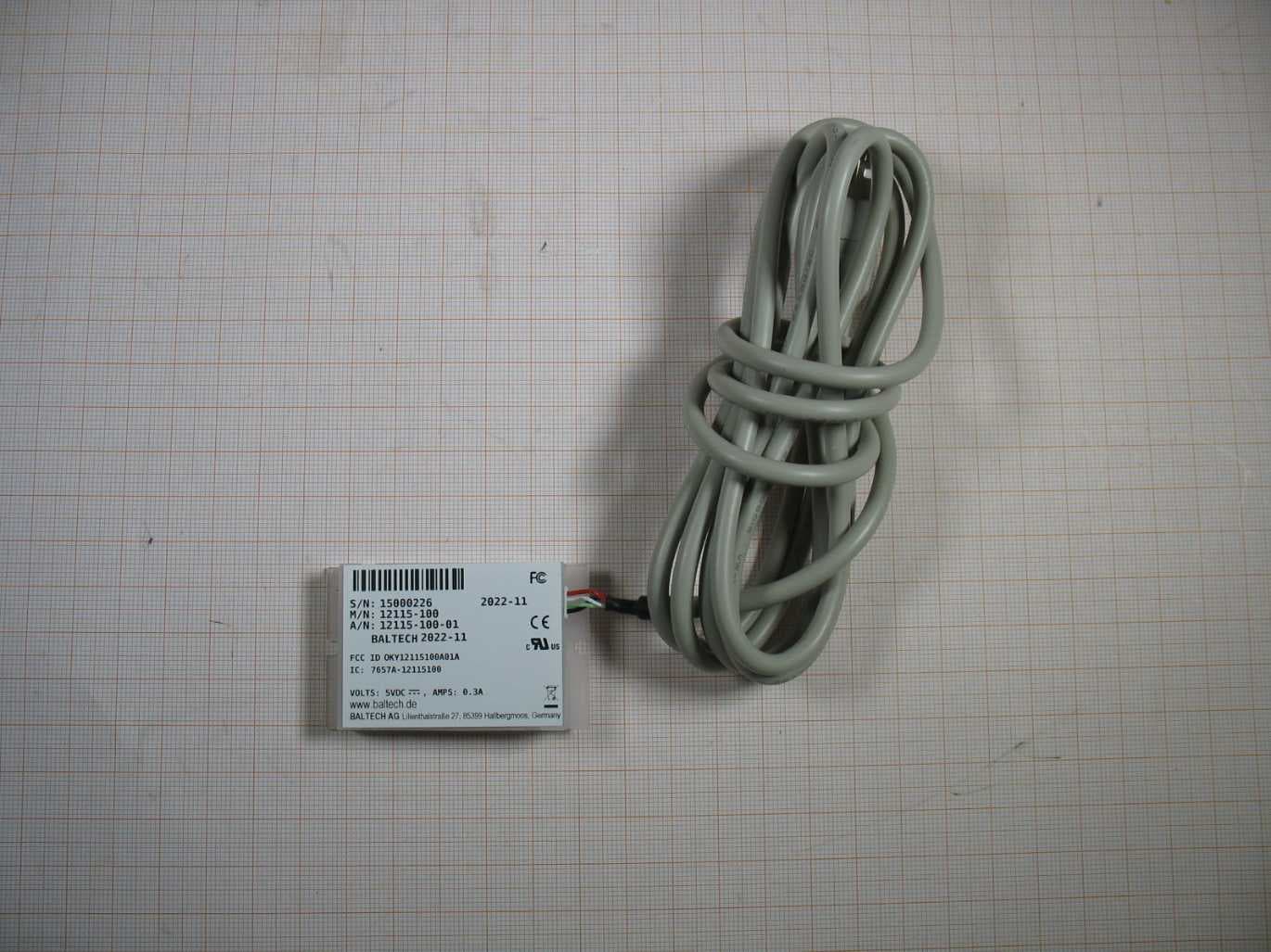
OKY12115100A01A
Jan 04, 2023RFID Card Reader
Equipment Class
DXX - Part 15 Low Power Communication Device Transmitter
OKY10115100A06A
Jul 26, 2021RFID Card Reader
Equipment Class
DXX - Part 15 Low Power Communication Device Transmitter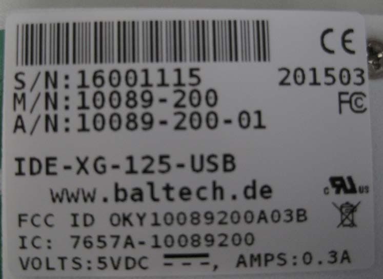
OKY10089200A03B
May 05, 2015IDE-XG-125-USB
Equipment Class
DXX - Part 15 Low Power Communication Device Transmitter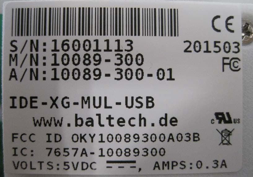
OKY10089300A03B
May 05, 2015IDE-XG-MUL-USB
Equipment Class
DXX - Part 15 Low Power Communication Device Transmitter