ONJ-3ECJ68B3EPTP Radio
Aviat Networks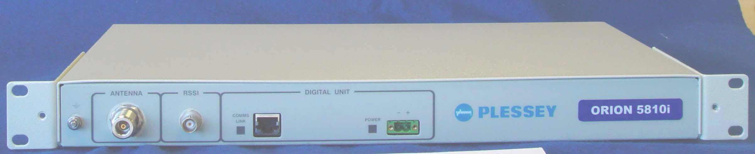
Click to zoom
Application Details
- Equipment Class
- DTS - Digital Transmission System
- Date of Grant
- Aug 12, 2003
- Application Purpose
- Original Equipment
- Date of Application
- Aug 12, 2003
- Equipment Note
- PTP Radio
- Frequency Range
- 5735.00000000 - 5840.00000000
- Company
- Aviat Networks
- Country
- Singapore
Documents & Files
Document Text
Text extracted from the exhibit documents filed with the FCC. Open a document above to read the original.
Users Manual
MDR2400/5800-SR, Orion2410/5810-SRi and Orion 5825-SR 862-01881 Issue 12c Page 1 MDR2400/5800-SR, Orion2410/5810-SRi and Orion5825-SR Digital Radios User Manual Document Number: 862-01881 MDR2400/5800-SR, Orion2410/5810-SRi and Orion 5825-SR 862-01881 Issue 12c Page 2 Issue Status Issue Revised Pages/Amendments 1 1 2 31 3 2 4 General – terminology definition PER used instead of BER to remove interpretation ambiguity between Block Error Rate and Bit Error Rate. Note Block (equivalent to packet) concept is still maintained within sections describing G.826 parameters to maintain consistency with G.826 terminology. 5 MIB Description chapter added, RESET Button Additions, chapter on setup of a serial connection between a PC/Laptop and the Element Management Port, IP network address description diagrams. 6 Amendments related to customer furnished equipment, RF Unit temperature range update, Maintenance and Ordering section updates, Appendix added regarding Antennas. 7 Update on RESET Button functionality description, MIB definition additions, product receive sensitivity level adjustment, FCC notice updates (Warning – this page, Antenna Information – Appendix E), NMS picture update. Appendix D Digital Indoor Unit firmware Upgrade Notice added. Appendix B MIB Elements ResetAllRFPerfomanceData and ResetAllG826 deprecated. 8 Added detail for new MDR2400 RF Unit Added detail for new Digital Indoor Unit – balanced and unbalanced connectors 9 Added detail for Orion 5825 – SR radio (16 QAM radio), 1+1 system. Changed to American English. Updated MIB as well as NMS, now JAVA based. Support for Windows XP, 2000 added. Added ftp firmware upload, Appendix G Added text required by the ATCB with regards to the Orion 5825 – SR. 10 Added additional text required by the ATCB to adhere to FCC requirements. 11 Added description of per trib line code selectivity for T1 interfaces. See Section 2.3.1. Added Appendix describing the Orion5810i and Orion2410i Indoor RF units. 12 Add text to describe the Orion5810-SRi and Orion2410-Sri and changes requested by Rheintech. 12c Add changes requested by ATCB. (Tx power of +25dBm for Orion5810i) MDR2400/5800-SR, Orion2410/5810-SRi and Orion 5825-SR 862-01881 Issue 12c Page 3 FEDERAL COMMUNICATIONS COMMISSION NOTICE The equipment has been tested and found to comply with the limits for a Class A digital devices, pursuant to Part 15 of the FCC Rules. These limits are designed to provide reasonable protection against harmful interference when the equipment is operated in a commercial environment. This equipment generates, uses, and can radiate radio frequency energy and, if not installed and used in accordance with the instruction manual, may cause harmful interference to radio communications. Operation of this equipment in a residential area is likely to cause harmful interference in which case the user will be required to correct the interference at his own expense. The manufacturer is not responsible for any radio or TV interference caused by unauthorized modifications to this equipment. Such modifications could void the user's authority to operate the equipment. This device complies with Part 15 of the FCC Rules. Operation is subject to the following two conditions: (1) this device may not cause interference, and (2) this device must accept any interference, including interference that may cause undesired operation of the device. WARNING- To comply with FCC RF exposure limits, the antennas for this transmitter must be fix-mounted to provide a separation distance of 2 meters (6.6 ft) or more from all persons to satisfy RF exposure requirements. Equipment installation and use This equipment must be professionally installed. The operator of the spread spectrum or digitally modulated intentional radiator, or the installer if the equipment is professionally installed, is responsible for ensuring that the system is used exclusively for fixed, point-to-point operations. NOTE 1 The MDR2400 frequency output must be limited to between 2412MHz and 2458MHz and the power to a maximum of +22dBm (2412-2426MHz) and +18dBm (2458MHz) for the required antennas for compliance to FCC standards, U.S. only. NOTE 2 The center frequencies of the ORION5850 radio is limited by firmware between 5731MHz and 5844MHz as outlined in Sections 2.2.1.4 and 2.2.1.5 and the transmit power is limited to +24dBm. The device must be used with one of the antennas listed below to comply with FCC standards: 1) Gabriel Electronics parabolic antenna, model number SSP2-52B 2) Harris Corporation flat panel antenna, model number MT-20004. NOTE 3 The center frequencies of the ORION5810i radio is limited by firmware between 5735MHz and 5840MHz as outlined in Section 2.2.1.1 and the transmit power is limited to +25dBm. The device must only be used with the antenna listed below to comply with FCC standards: 1) Gabriel Electronics parabolic antenna, model number SSP2-52B INDUSTRY CANADA NOTICE This device has been designed to operate with an antenna having a maximum gain of 33 dBi. Antenna having a higher gain is strictly prohibited per regulations of Industry Canada. The required antenna impedance is 50 ohms. Operation is subject to the following two conditions: (1) this device may not cause interference, and (2) this device must accept any interference, including interference that may cause undesired operation of the device. Exposure of Humans to RF Fields The installer of this radio equipment must ensure that the antenna is located or pointed such that it does not emit RF field in excess of Health Canada limits for the general population; consult Safety Code 6, obtainable from Health Canada's website: www.hc-sc.gc.ca/rpb MDR2400/5800-SR, Orion2410/5810-SRi and Orion 5825-SR 862-01881 Issue 12c Page 4 Publication Number: 862-01881 Issue 12 March 2003 © 2003 Tellumat (Pty) Limited The information contained herein is the property of Tellumat (Pty) Limited and is supplied without liability for errors or omissions. No part may b…
Text truncated - open the document above for the full version.
Users Manual
MDR2400/5800-SR, Orion2410/5810-SRi and Orion 5825-SR 862-01881 Issue 12c Page 77 4. Once setup, use the following screens to set up the COM port’s parameters. MDR2400/5800-SR, Orion2410/5810-SRi and Orion 5825-SR 862-01881 Issue 12c Page 78 A.4 Adding Dial-up Networking : Windows 95/98 1. After adding the modem, set up the connection properties using the following screens as a guideline. This will allow establishment of a PPP connection between the computer and the DIU’s Element Manager port. A Null_Modem connection option as shown below will be created. If one doesn’t exist, double click on the “Make New Connection” icon. MDR2400/5800-SR, Orion2410/5810-SRi and Orion 5825-SR 862-01881 Issue 12c Page 79 MDR2400/5800-SR, Orion2410/5810-SRi and Orion 5825-SR 862-01881 Issue 12c Page 80 A.5 Adding Dial-up Networking : Windows 2000 / Windows XP A.5.1 To add dial-up networking The installation procedure documented here is based on the procedure that should be followed for Windows 2000. Some of the configuration windows for Windows XP may look slightly different, and may appear in a different order, but the basic procedure are the same as for Windows 2000 and are therefore not repeated in an attempt to reduce the size of this user manual. 1. Select the Make New Connection menu item. Win2000 & Win-XP MDR2400/5800-SR, Orion2410/5810-SRi and Orion 5825-SR 862-01881 Issue 12c Page 81 2. Select the Connect directly to another computer and press the Next button. Win2000 Win-XP MDR2400/5800-SR, Orion2410/5810-SRi and Orion 5825-SR 862-01881 Issue 12c Page 82 3. Set the dialup connection to connect as Guest and press the Next button. Win2000 & Win-XP 4. Select the COM port you intend to use to connect to the radio from the Select Device dropdown box and press the Next button. In Windows XP, this window is preceded by Step 6 below. Win2000 & Win-XP MDR2400/5800-SR, Orion2410/5810-SRi and Orion 5825-SR 862-01881 Issue 12c Page 83 5. Select the users that must be able to use this dialup connection and press the Next button. Win2000 & Win-XP MDR2400/5800-SR, Orion2410/5810-SRi and Orion 5825-SR 862-01881 Issue 12c Page 84 6. Enter the name of this dialup connection and press the Finish button. This name may be any name of your choice. The connection is now installed, but its properties must still be configured. This window is displayed earlier in Windows XP. Win2000 & Win-XP 7. Finish installing the connection (Windows XP only) Win-XP MDR2400/5800-SR, Orion2410/5810-SRi and Orion 5825-SR 862-01881 Issue 12c Page 85 8. Browse to the newly added connection under the Network and Dial-Up connections menu item of Windows, and right-click on the connection with your mouse. Select the Properties item from the pop-up menu to bring up the properties window below. Now click on the Configure button below the Select a Device combo box in the General properties tab window to bring up the Modem Configuration box below. Make sure that all the settings on your PC are the same is in this window (Maximum speed: 115200 bps & hardware flow control enabled). Now press the OK button. Win2000 & Win-XP 9. In the Options properties box below, select Redial if line is dropped and press the OK button. Win2000 & Win-XP MDR2400/5800-SR, Orion2410/5810-SRi and Orion 5825-SR 862-01881 Issue 12c Page 86 10. Browse to the newly added connection under the Network and Dial-Up connections menu item of Windows, and left-click on the connection with your mouse. This will bring up the connection window below. The values of the Username and Password fields does not matter, press Connect to dial into the radio once the dialup cable has been plugged into the Digital Indoor Unit and the PC. Win2000 & Win-XP MDR2400/5800-SR, Orion2410/5810-SRi and Orion 5825-SR 862-01881 Issue 12c Page 87 B Appendix: MANAGEMENT OF THE MDR2400-SR MDR5800-SR and the Orion 5825-sr All management of the MDR and Orion products are implemented using SNMP (Simple Network Management Protocol), an open standard. The products can be managed by: 1. Standard SNMP managers such as HP OpenView or SNMPc i.e. there is Open Network Management compatibility. 2. For rapid product installation, the NMS GUI Application (hereafter referred to as the NMS-GA) provides extensive management functions on site and, via the microwave radio link, can be used to access the MDR / Orion station on the opposite side of the link. The NMS-GA is a software application that runs on a PC workstation such as a laptop or notebook computer that is connected to an MDR / Orion Digital Indoor Unit serial port (DB9 DTE) or an Ethernet connection (10BaseT DTE), both accessed via the DIU front-panel. B.1 SNMP and the MDR / Orion Use of SNMP within the product allows remote: configuration, monitoring of performance, notification of alarms and firmware upgrades via an IP-network. Within an IP network supporting routing of IP data, the radios can be supported from any remote location. The product can be accessed via the Internet if the necessary gateways are provided. A GSM/PCS modem dial-up capability provides another remote management option. The Digital Indoor Units have built-in SNMP agents and an extensive MIB (Management Information Base). The MDR /Orion product uses SNMP V1 (RFC1155, 1157). The user has access to an Enterprise MIB (obtainable though customer services) and MIB II (RFC 1213). Access to the MIB via the DIU SNMP agent is via Ethernet (10BaseT interface on the product's front panel) or PPP (RFC 1661) via the product's serial channel Element Manager port. The use of SNMP provides flexibility for operators with central equipment monitoring. It provides management access to radio configuration (all data interfaces), interface status and statistics, fault and maintenance information. SNMP security (if enabled) is ensured by using a login and password to give the user "administrator" or "standard user" rights. The "standard user rights" option limits the ability to SET MIB variables. NOTE Secure SNMP…
Text truncated - open the document above for the full version.
Cover Letter(s)
Rhein Tech Laboratories Client: Tellumat (Pty) Ltd. 360 Herndon Parkway FCC: Part 15.247 Suite 1400 Industry Canada: RSS-210 FCC ID: ONJ-3ECJ68B3E Herndon, VA 20170 http://www.rheintech.com Model Name: ORION 5810i Page 35 of 50 APPENDIX D: CONFIDENTIALITY REQUEST LETTER Please refer to the following page. Tellumat (Pty) Limited 64-74 White Rd Retreat Cape Town South Africa * PO Box 30451, Tokai 7966 South Africa DIRECTORS: Dr. J.A. Temple (Chairman), L.C. Jones (Managing), P.B. Hobbs, C.J. Meintjes, R.J. Shaw, Dr. S. Sibisi, J. de V. van Zyl, M. Higgins, K.A. Alborough (Alt), J.W. Grobler (Alt), M.D. Chewins (Alt) Registration Number: 96/00957/07 Tel: +27 21 710-2911 Fax: +27 21 712-1278 e-mail: [email protected] Web: http://www.tellumat.com 16 May 2003 Federal Communications Commission 7435 Oakland Mills Road Columbia, MD 21046 To Whom It May Concern: The following information is to be held confidential pursuant of 47 CFR Part 0 §0.457 and Section 552(b)(4) of the Freedom of Information Act, because the information provided contains trade secrets and proprietary. If made public, the information might be used to the disadvantage of the applicant in the market place. Schematics Product Description Yours faithfully For Tellumat (Pty) Limited Dr Douw van der Merwe Technical Director Broadband Wireless Block Diagrams
Cover Letter(s)
Rhein Tech Laboratories Client: Tellumat (Pty) Ltd. 360 Herndon Parkway FCC: Part 15.247 Suite 1400 Industry Canada: RSS-210 FCC ID: ONJ-3ECJ68B3E Herndon, VA 20170 http://www.rheintech.com Model Name: ORION 5810i Page 34 of 50 APPENDIX C: AGENCY AUTHORIZATION LETTER Please refer to the following page. Tellumat (Pty) Limited 64-74 White Rd Retreat Cape Town South Africa * PO Box 30451, Tokai 7966 South Africa DIRECTORS: Dr. J.A. Temple (Chairman), L.C. Jones (Managing), P.B. Hobbs, C.J. Meintjes, R.J. Shaw, Dr. S. Sibisi, J. de V. van Zyl, M. Higgins, K.A. Alborough (Alt), J.W. Grobler (Alt), M.D. Chewins (Alt) Registration Number: 96/00957/07 Tel: +27 21 710-2911 Fax: +27 21 712-1278 e-mail: [email protected] Web: http://www.tellumat.com 16 May 2003 American Telecommunications Certification Body, Inc. 6731 Whittier Avenue Suite C110 McLean, VA 22101 To Whom It May Concern: Please be advised that Tellumat (Pty) Limited authorizes Rhein Tech Laboratories, Inc. to act on our behalf, until otherwise notified, for applications submitted to the above competent body. We certify that we are not subject to denial of federal benefits, that includes FCC benefits, pursuant to Section 5301 of the Anti-Drug abuse ACT of 1988, U.S.C. 682 and as defined in 47 CFR Part 1 §1.2002(b). Yours faithfully For Tellumat (Pty) Limited Dr Douw van der Merwe Technical Director Broadband Wireless
Cover Letter(s)
American Telecommunications Certification Body Inc. 6731 Whittier Ave, McLean, VA 22101 August 10, 2003 RE: FCC ID: ONJ-3ECJ68B3E_ATCB000665 Attention: Kathy Grzovic / Rick McMurray I have a few comments on this Application. 1. Please remove the shielding form the PSU/TCXO Bottom Assembly and show the circuitry underneath. - 2. Please note that the specs say the device has a power range of +2 to 24dBm. Please note that the power measured was 24.4dBm. This exceeds the maximum power specification. Please explain. - 3. FYI - Please note that your non-modification statement (The manufacturer is not responsible for any radio or TV interference caused by unauthorized modifications to this equipment. Such modifications could void the user's authority to operate the equipment.) appears to speak only to those modifications that cause interference. This is not the intent of the non- modification clause. The non-modification clause is intended to address any and all unauthorized modifications, regardless if they cause interference or not. The modification clause shall inform the user that “changes or modifications not expressly approved by the party responsible for compliance could void the user's authority to operate the equipment.” - 4. Please note that there appears to be copper tape on the dish shown in the setup photos. Is this a modification to the antenna? If so, what purpose does the tape perform. IF this is not a modification to the antenna, please verify. - 5. Please note that 2.1033(a)(6) states that, “The report shall include sample calculations showing how the measurement results were converted for comparison with the technical requirements.” This is especially important when you lump all correction factors into one “site factor”. Please provide or please show where in the report these sample calculations are located. - Dennis Ward mailto:[email protected] The items indicated above must be submitted before processing can continue on the above referenced application. Failure to provide the requested information may result in application termination. Correspondence should be considered part of the permanent submission and may be viewed from the Internet after a Grant of Equipment Authorization is issued. Please do not respond to this correspondence using the email reply button. In order for your response to be processed expeditiously, you must submit your documents through the AmericanTCB.com website. Also, please note that partial responses increase processing time and should not be submitted. Any questions about the content of this correspondence should be directed to the sender.
Cover Letter(s)
American Telecommunications Certification Body Inc. 6731 Whittier Ave, McLean, VA 22101 August 11, 2003 RE: FCC ID: ONJ-3ECJ68B3E_ATCB000665 Attention: Kathy Grzovic / Rick McMurray I have a few comments on this Application. 1. Please remove the shielding from the PSU/TCXO Bottom Assembly and show the circuitry underneath. Response : Please note that this picture was shown on page 1 of the following exhibit which was uploaded with the original application. The picture with the shielded was shown in another exhibit, which perhaps led to this comment. “Plessey 2003129 ORION 5810i FCC & IC Test Report APX L IntPh Pt 2.pdf” 2. Please note that the specs say the device has a power range of +2 to 24dBm. Please note that the power measured was 24.4dBm. This exceeds the maximum power specification. Please explain. Response : The 24 dBm stated in the user’s manual represents a nominal power rating. The power levels presented in the report were actual measured power levels of the device as tested. This device is well within the power level requirements of FCC Part 15.247(b)(3). 3. FYI - Please note that your non-modification statement (The manufacturer is not responsible for any radio or TV interference caused by unauthorized modifications to this equipment. Such modifications could void the user's authority to operate the equipment.) appears to speak only to those modifications that cause interference. This is not the intent of the non-modification clause. The non- modification clause is intended to address any and all unauthorized modifications, regardless if they cause interference or not. The modification clause shall inform the user that “changes or modifications not expressly approved by the party responsible for compliance could void the user's authority to operate the equipment.” Response : This is noted, and the client has been advised to update this statement in the manual. 4. Please note that there appears to be copper tape on the dish shown in the setup photos. Is this a modification to the antenna? If so, what purpose does the tape perform. IF this is not a modification to the antenna, please verify. Response : The tape shown on the dish is made of non-metallic material, not copper. The tape was used to steady the antenna during testing. 5. Please note that 2.1033(a)(6) states that, “The report shall include sample calculations showing how the measurement results were converted for comparison with the technical requirements.” This is especially important when you lump all correction factors into one “site factor”. Please provide or please show where in the report these sample calculations are located. Response: The statement in regard to Part 2.1033(a)(6) has been included in section 5.1 of the revised test report uploaded with this response. Dennis Ward mailto:[email protected] The items indicated above must be submitted before processing can continue on the above referenced American Telecommunications Certification Body Inc. 6731 Whittier Ave, McLean, VA 22101 application. Failure to provide the requested information may result in application termination. Correspondence should be considered part of the permanent submission and may be viewed from the Internet after a Grant of Equipment Authorization is issued. Please do not respond to this correspondence using the email reply button. In order for your response to be processed expeditiously, you must submit your documents through the AmericanTCB.com website. Also, please note that partial responses increase processing time and should not be submitted. Any questions about the content of this correspondence should be directed to the sender.
External Photos
Rhein Tech Laboratories Client: Tellumat (Pty) Ltd. 360 Herndon Parkway FCC: Part 15.247 Suite 1400 Industry Canada: RSS-210 FCC ID: ONJ-3ECJ68B3E Herndon, VA 20170 http://www.rheintech.com Model Name: ORION 5810i Page 45 of 50 APPENDIX K: EXTERNAL PHOTOGRAPHS Please see the following page. Indoor RF Unit Front Indoor RF Unit Back
ID Label/Location Info
Rhein Tech Laboratories Client: Tellumat (Pty) Ltd. 360 Herndon Parkway FCC: Part 15.247 Suite 1400 Industry Canada: RSS-210 FCC ID: ONJ-3ECJ68B3E Herndon, VA 20170 http://www.rheintech.com Model Name: ORION 5810i Page 37 of 50 APPENDIX F: LABEL AND LABEL LOCATION Please see the following page for a diagram of the FCC ID label location, with a sample label. Sample FCC ID label (affixed to back of RF Unit): Two part FCC Statement (label affixed to back of RF Unit): Indoor RF Unit Rear View with FCC ID Label and 2 Part Statement Label Placement FCC 2 Part Statement
Test Setup Photos
Rhein Tech Laboratories Client: Tellumat (Pty) Ltd. 360 Herndon Parkway FCC: Part 15.247 Suite 1400 Industry Canada: RSS-210 FCC ID: ONJ-3ECJ68B3E Herndon, VA 20170 http://www.rheintech.com Model Name: ORION 5810i Page 41 of 50 APPENDIX J: TEST PHOTOGRAPHS PHOTOGRAPH 1: RADIATED EMISSION FRONT VIEW – PARABOLIC ANTENNA Rhein Tech Laboratories Client: Tellumat (Pty) Ltd. 360 Herndon Parkway FCC: Part 15.247 Suite 1400 Industry Canada: RSS-210 FCC ID: ONJ-3ECJ68B3E Herndon, VA 20170 http://www.rheintech.com Model Name: ORION 5810i Page 42 of 50 PHOTOGRAPH 2: RADIATED EMISSIONS REAR VIEW - PARABOLIC ANTENNA Rhein Tech Laboratories Client: Tellumat (Pty) Ltd. 360 Herndon Parkway FCC: Part 15.247 Suite 1400 Industry Canada: RSS-210 FCC ID: ONJ-3ECJ68B3E Herndon, VA 20170 http://www.rheintech.com Model Name: ORION 5810i Page 43 of 50 PHOTOGRAPH 3: CONDUCTED EMISSIONS FRONT VIEW - PARABOLIC ANTENNA Rhein Tech Laboratories Client: Tellumat (Pty) Ltd. 360 Herndon Parkway FCC: Part 15.247 Suite 1400 Industry Canada: RSS-210 FCC ID: ONJ-3ECJ68B3E Herndon, VA 20170 http://www.rheintech.com Model Name: ORION 5810i Page 44 of 50 PHOTOGRAPH 4: CONDUCTED EMISSIONS REAR VIEW - PARABOLIC ANTENNA
Contact Information
Applicant
Ruth French(Product Compliance Manager)
Technical Contact
Rhein Tech Laboratories, Inc.Rick McMurray
[email protected]703-689-0368
360 Herndon Parkway, Suite 1400 · Herndon, Virginia · United States
Test Firm
Rhein Tech Laboratories, Inc.Rick McMurray
Technical Specifications
| # | Rule Parts | Frequency Range | Power Output |
|---|---|---|---|
| 1 | 15C | 5.74 GHz - 5.84 GHz | 275.00 mW |
Other Applications from Aviat Networks
ONJ-3ECJ68A4D
Jul 06, 2003Digital Radio
Equipment Class
DTS - Digital Transmission System
ONJ-MDR2400ET
Jun 19, 2002Digital Radio
Equipment Class
DSS - Part 15 Spread Spectrum Transmitter
ONJ-MDR5800ET
May 14, 2001Point to Point Spread Spectrum Transceiver
Equipment Class
DSS - Part 15 Spread Spectrum Transmitter
ONJMDR8500
May 01, 2001Point to Point Spread Spectrum Transceiver
Equipment Class
DSS - Part 15 Spread Spectrum Transmitter
ONJMDR2400-THD
Mar 14, 2000Diplexer System for WLAN
Equipment Class
DSS - Part 15 Spread Spectrum Transmitter