ONJMDR2400-THDDiplexer System for WLAN
Aviat Networks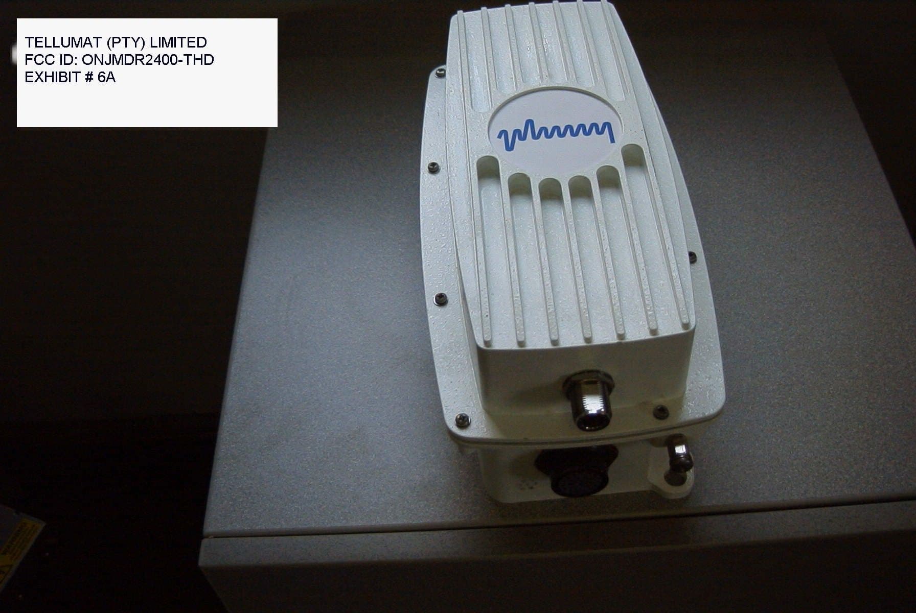
Click to zoom
Application Details
- Equipment Class
- DSS - Part 15 Spread Spectrum Transmitter
- Date of Grant
- Mar 14, 2000
- Application Purpose
- Original Equipment
- Date of Application
- Aug 23, 1999
- Equipment Note
- Diplexer System for WLAN
- Frequency Range
- 2412.00000000 - 2455.00000000
- Company
- Aviat Networks
- Country
- Singapore
Documents & Files
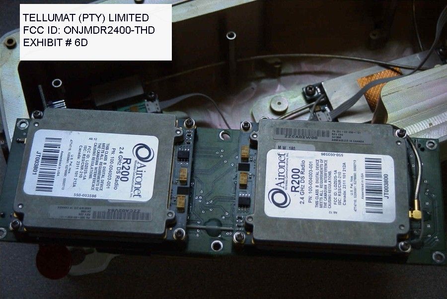
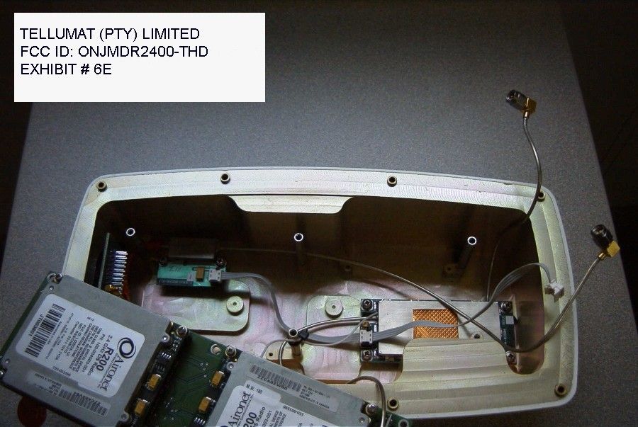
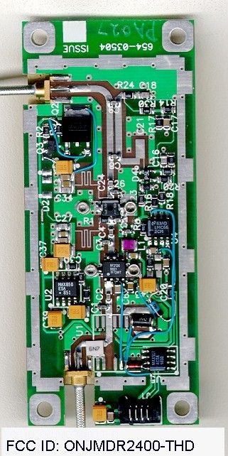
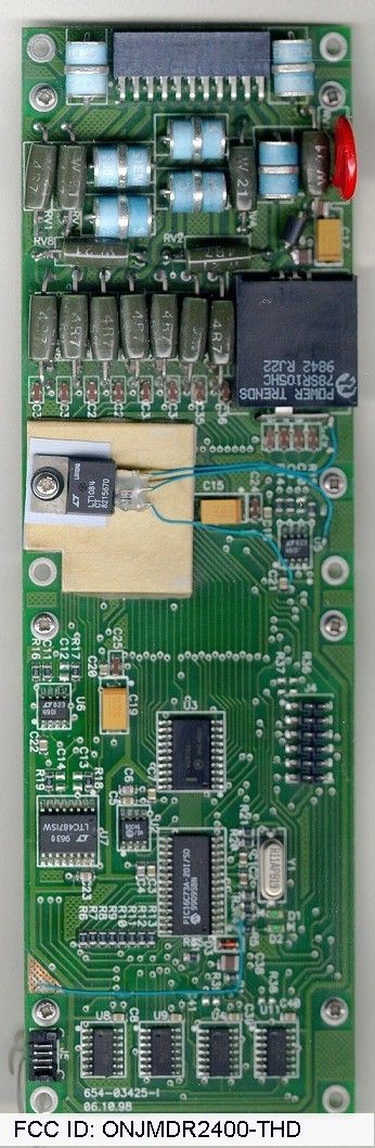
Document Text
Text extracted from the exhibit documents filed with the FCC. Open a document above to read the original.
Users Manual
862-01545μLink System Manual Issue 1bPage i μμLink Digital Radio System Manual Publication Number: 862-01545 Issue 1b February 1999 Tellumat (Pty) Limited Reg. No. 96/000957/07 64/74 White Road, Retreat, 7945 P.O. Box 30451, Tokai, 7966 Telephone: +27 21 710-2911 Fax No. +27 21 710-2333 μLink System Manual862-01545 Page iiIssue 1b Federal Communications Commission Notice NOTE The equipment has been tested and found to comply with the limits for a Class A digital devices, pursuant to Part 15 of the FCC Rules. These limits are designed to provide reasonable protection against harmful interference when the equipment is operated in a commercial environment. This equipment generates, uses, and can radiate radio frequency energy and, if not installed and used in accordance with the instruction manual, may cause harmful interference to radio communications. Operation of this equipment in a residential area is likely to cause harmful interference in which case the user will be required to correct the interference at his own expense. The manufacturer is not responsible for any radio or TV interference caused by unauthorised modifications to this equipment. Such modifications could void the user's authority to operate the equipment. This device complies with Part 15 of the FCC Rules. Operation is subject to the following two conditions: (1) this device may not cause interference, and (2) this device must accept any interference, including interference that may cause undesired operation of the device. This equipment must be professionally installed. WARNING- To comply with FCC RF exposure limits, the antennas for this transmitter must be fix- mounted to provide a separation distance of 1 meter (3.5 ft) or more from all persons to satisfy RF exposure requirements. 862-01545μLink System Manual Issue 1bPage iii Document Issue Status When an issue status of this manual changes, the record below must be completed and initialled. Page No. Issue Status Authority (ECN No.) Page No. Issue Status Authority (ECN No.) 1 - 781 1 - 821b μLink System Manual862-01545 Page ivIssue 1b Table of Contents Page Chapter 1: Purpose and Planning............................................................1 Introduction to Chapter 1...................................................................1 μLink Product Family........................................................................1 Role and Purpose................................................................................1 System Description......................................................................................2 System Overview................................................................................2 Features..............................................................................................2 System Configuration Options............................................................5 Interface Definitions...........................................................................6 Planning Information.........................................................................7 Site Evaluation..............................................................................7 Multipath Effects...........................................................................8 Installation Information......................................................................9 General Information......................................................................9 Indoor Unit....................................................................................9 Outdoor Unit and Antenna.............................................................9 Operational Capabilities...................................................................10 Maintenance Features.......................................................................11 Built-in Test Features..................................................................11 System Specifications.......................................................................12 Performance Characteristics.........................................................12 Data Transmission Characteristics...............................................12 Transmitter Characteristics..........................................................13 Receiver Characteristics...............................................................13 Wayside Service Channel.............................................................14 Auxiliary/Alarm Interfaces..........................................................14 Power Supply Characteristics.......................................................15 Controls and Displays..................................................................15 Antenna Characteristics (μLink -T).............................................16 Equipment Status Monitoring......................................................17 Mechanical Characteristics..........................................................18 Environmental Characteristics.....................................................18 Frequency Band Plan........................................................................19 862-01545μLink System Manual Issue 1bPage v Chapter 2: Installation............................................................................21 Introduction to Chapter 2..................................................................21 Site Requirements.............................................................................21 Parts and Accessories Supplied for Installation.................................22 Customer Furnished Tools and Equipment........................................23 Installation Overview........................................................................24 Antenna Installation.....................................................................24 Outdoor Unit Installation.............................................................26 Indoor Unit Installation.................................................…
Text truncated - open the document above for the full version.
Users Manual
862-01545μLink System Manual Issue 1bPage i μμLink Digital Radio System Manual Publication Number: 862-01545 Issue 1b February 1999 Tellumat (Pty) Limited Reg. No. 96/000957/07 64/74 White Road, Retreat, 7945 P.O. Box 30451, Tokai, 7966 Telephone: +27 21 710-2911 Fax No. +27 21 710-2333 μLink System Manual862-01545 Page iiIssue 1b Federal Communications Commission Notice NOTE The equipment has been tested and found to comply with the limits for a Class A digital devices, pursuant to Part 15 of the FCC Rules. These limits are designed to provide reasonable protection against harmful interference when the equipment is operated in a commercial environment. This equipment generates, uses, and can radiate radio frequency energy and, if not installed and used in accordance with the instruction manual, may cause harmful interference to radio communications. Operation of this equipment in a residential area is likely to cause harmful interference in which case the user will be required to correct the interference at his own expense. The manufacturer is not responsible for any radio or TV interference caused by unauthorised modifications to this equipment. Such modifications could void the user's authority to operate the equipment. This device complies with Part 15 of the FCC Rules. Operation is subject to the following two conditions: (1) this device may not cause interference, and (2) this device must accept any interference, including interference that may cause undesired operation of the device. This equipment must be professionally installed. WARNING- To comply with FCC RF exposure limits, the antennas for this transmitter must be fix- mounted to provide a separation distance of 1 meter (3.5 ft) or more from all persons to satisfy RF exposure requirements. 862-01545μLink System Manual Issue 1bPage iii Document Issue Status When an issue status of this manual changes, the record below must be completed and initialled. Page No. Issue Status Authority (ECN No.) Page No. Issue Status Authority (ECN No.) 1 - 781 1 - 821b μLink System Manual862-01545 Page ivIssue 1b Table of Contents Page Chapter 1: Purpose and Planning............................................................1 Introduction to Chapter 1...................................................................1 μLink Product Family........................................................................1 Role and Purpose................................................................................1 System Description......................................................................................2 System Overview................................................................................2 Features..............................................................................................2 System Configuration Options............................................................5 Interface Definitions...........................................................................6 Planning Information.........................................................................7 Site Evaluation..............................................................................7 Multipath Effects...........................................................................8 Installation Information......................................................................9 General Information......................................................................9 Indoor Unit....................................................................................9 Outdoor Unit and Antenna.............................................................9 Operational Capabilities...................................................................10 Maintenance Features.......................................................................11 Built-in Test Features..................................................................11 System Specifications.......................................................................12 Performance Characteristics.........................................................12 Data Transmission Characteristics...............................................12 Transmitter Characteristics..........................................................13 Receiver Characteristics...............................................................13 Wayside Service Channel.............................................................14 Auxiliary/Alarm Interfaces..........................................................14 Power Supply Characteristics.......................................................15 Controls and Displays..................................................................15 Antenna Characteristics (μLink -T).............................................16 Equipment Status Monitoring......................................................17 Mechanical Characteristics..........................................................18 Environmental Characteristics.....................................................18 Frequency Band Plan........................................................................19 862-01545μLink System Manual Issue 1bPage v Chapter 2: Installation............................................................................21 Introduction to Chapter 2..................................................................21 Site Requirements.............................................................................21 Parts and Accessories Supplied for Installation.................................22 Customer Furnished Tools and Equipment........................................23 Installation Overview........................................................................24 Antenna Installation.....................................................................24 Outdoor Unit Installation.............................................................26 Indoor Unit Installation.................................................…
Text truncated - open the document above for the full version.
Cover Letter(s)
Tellumat (Pty) Limited 64-74 White Road, Retreat 7945 P.O. Box 30451, Tokai 7966 South Africa DIRECTORS: Dr. J.A. Temple (Chairman), L.C. Jones (Managing), P.B. Hobbs, C.J. Meintjes R.J. Shaw, Dr. S. Sibisi, J. de V. van Zyl, M. Higgins, K.A. Alborough (Alt), J.W. Grobler (Alt), M. D. Chewins (Alt) Registration Number: 96/00957/07 Tel: +27 (21) 710-2911 Fax: +27 (21) 710-2360 22 September 1999 Federal Communications Commission Authorisation & Evaluation Division 7435 Oakland Mills Road Columbia, Maryland 21046 To Whom It May Concern: Tellumat (Pty) Limited hereby requests that all circuit diagrams submitted to the FCC be treated with the strictest confidentiality. All information is proprietary and the sole property of Tellumat (Pty) Limited, and as such should not be made available to any third party Sincerely Tellumat (Pty) Limited pp S.J. Fouche Manager – Tellumat Microwave & RF Products
Cover Letter(s)
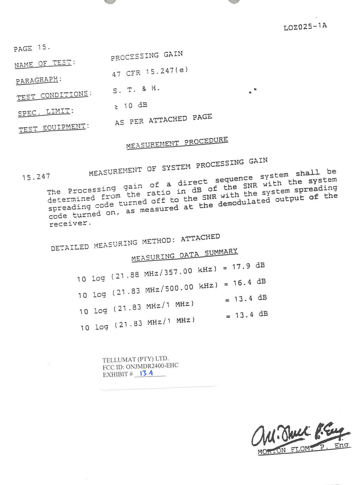
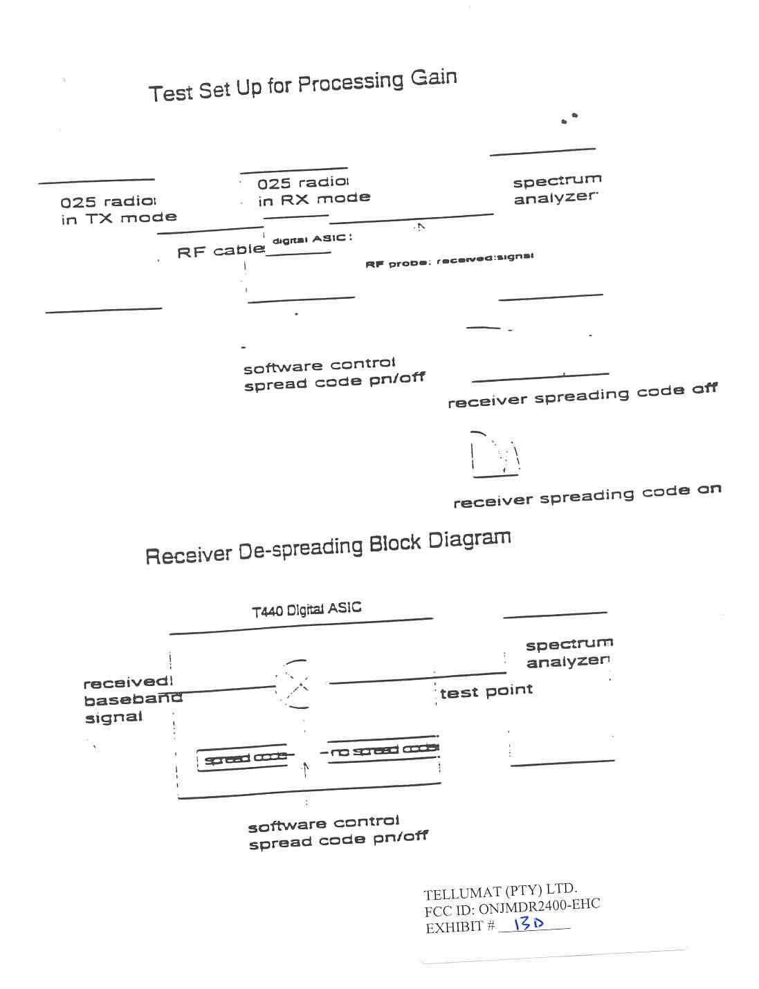
TIMCO ENGINEERING INC. PO Box 370 849 SR 45 Newberry, Florida 32669 Ph. 352.472.5500 Fax. 352.331.8840 [email protected] 10/29/99 TO: GREG CZUMAK FCC Subject: FCCID: ONJMDR2400-THD REFERENCE: EA95224 1. Sorry for the typo, frequency range should be 2412 to 2455MHz. 2. The manufacturer has agreed to limit their upper frequency to 2455MHz in order to meet the requirements in the restricted band at 2483.5MHz. 3. Attached you will find a new block diagrams. 4. The gain of the Yagi is 17dBi and the Parabolic is 24dBi. I’ve attached processing gain information. 5. Attached you will find new radiation measurements. 6. The Processing gain is 13.4dB. 7. The Theory of operation is attached. 8. The schematics have been sent to you by the manufacturer on 9/28. 9. I’ve sent a revised request for confidentiality letter. Only the schematic should remain confidential. Please let me know if you need any further information. Thanks for your help. BEST REGARDS, Sid Sanders CHECK OUT OUR WEBSITE @www.timcoengr.com
Cover Letter(s)
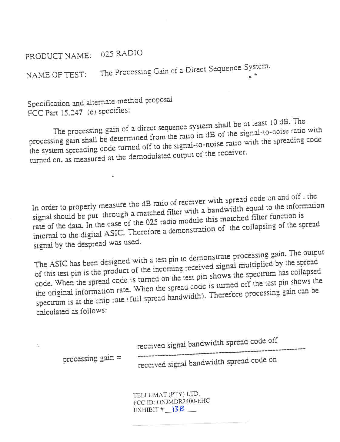
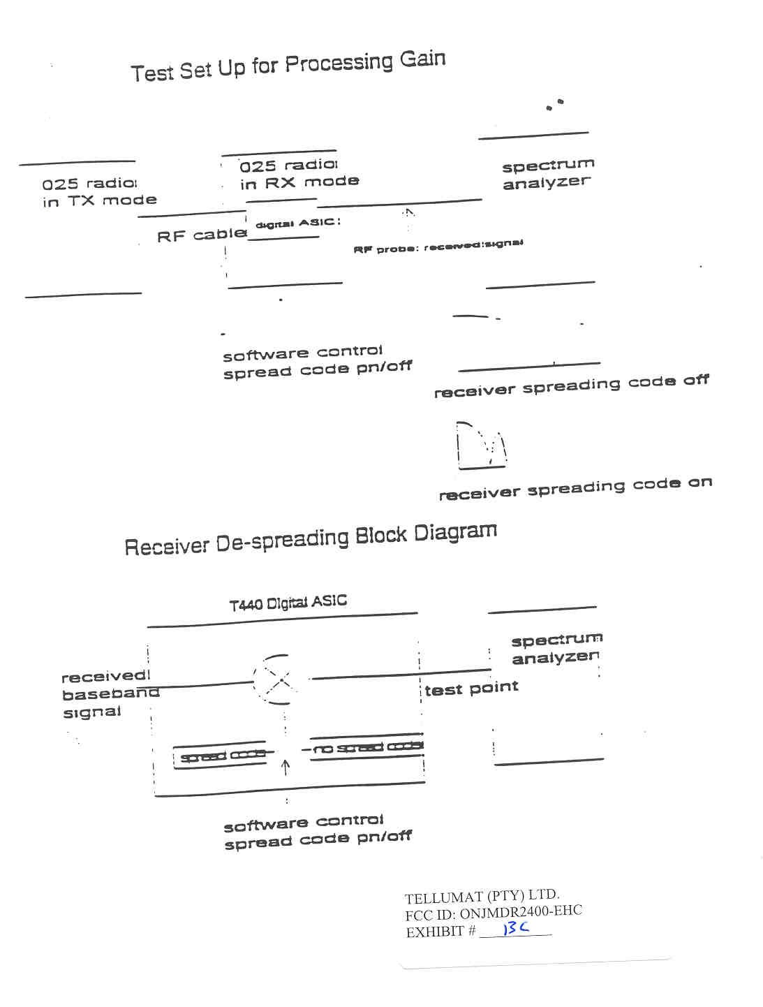
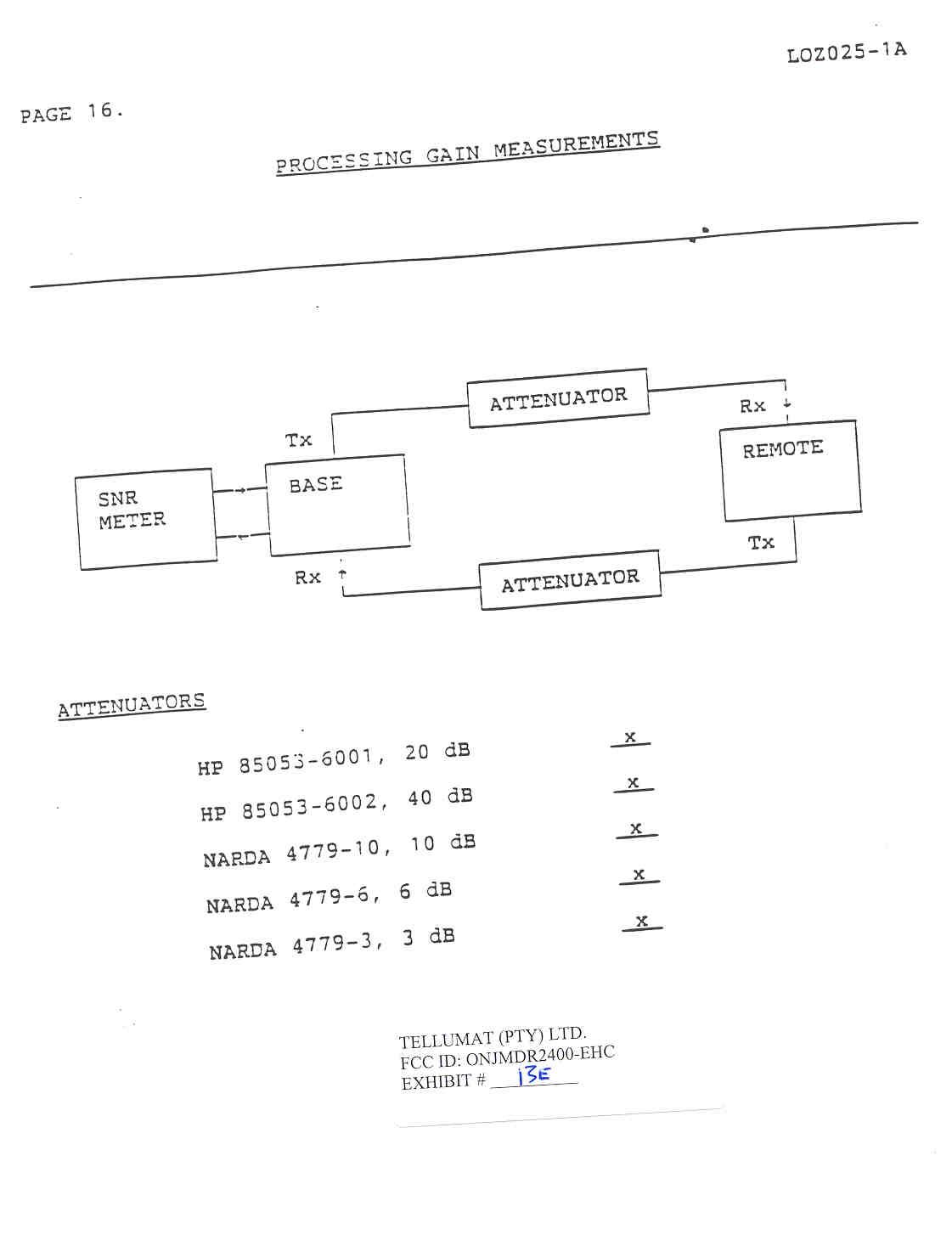
TELEPHONE: (352) 472-5500 (888) 472-2424 FAX: (352) 472-2030 E-MAIL: [email protected] Engineering, Inc.WEBSITE: www.timcoengr.com TIMCO ENGINEERING, INC. 849 N. W. STATE ROAD 45 P.O. BOX 370 NEWBERRY, FL 32669 December 2, 1999 Mr. Greg Czumak Federal Communications Commission Ref: Tellumat (Pty) Limited’s FCC ID: ONJMDR2400-THD Subject: Your Correspondence ID # 10578 Dear Greg: With reference to the processing gain, the following information is what my customer supplied me with: The test done is the proper processing gain test; where the radio of the SNR with the spreading turned off, is compared to the SNR with the spreading on. This is the most accurate and accepted way of determining the processing gain. The test report mentions the change in bandwidth when turning the spreading on and off. This is simply to determine that the action of the test pin on the ASIC, to turn the spreading off, is functioning, and that the bandwidth indeed collapses to the chip rate. The last page of the processing gain clearly shows the SNR meter being used to determine the signal to noise ratio. This test was performed on the Aironet module in th original application and supported by the Aironet test report; which was approved by the FCC. Should you have any questions or require any further information, please advise. Regards, Sharon Hoffman/TIMCO ENGINEERING, INC.
Cover Letter(s)
TIMCO ENGINEERING INC. 849 NW State Road 45 NEWBERRY, FLORIDA 32669 [email protected] 888.472.2424 Mr. Greg Czumak FCC SUBJECT: FCCID: ONJMDR2400-THD REFERENCE: EA95224 Attached you will new measurements of this unit with both power levels, 0.40Watts & 0.220Watts. 1. Attached you will new power output measurements. 2. Attached you will find new radiated emissions measurements. 3. Attached you will find PSD measurements for both 400mW & 220mW. 4. You are correct the power output for the 24dBi antenna should be 400mW. 5. I have sent a complete new manual which covers all of the RF Exposure requirements. Should you have any questions or require any further information, please advise. Sincerely, Sid Sanders
Operational Description
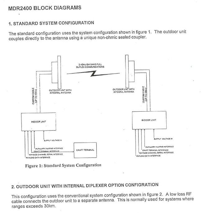
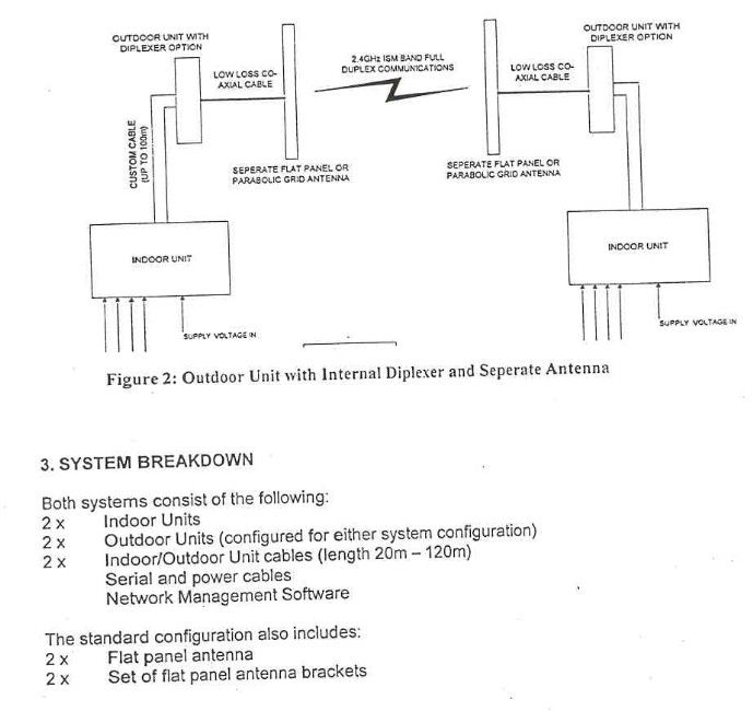
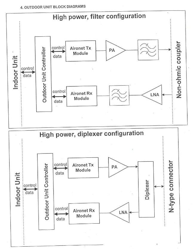
Theory of Operation of a MDR (Microwave Digital Radio) 2400 Radio Diplexer System : T1 Operation Introduction A MDR link may consist of at least one complementary pair of MDR2400 stations that may be extended over longer distances by linking further station pairs in a multiple hop configuration. A single MDR2400 station comprises an Indoor Unit and an Outdoor Unit interconnected by a custom cable. The MDR system is a full duplex, point-to-point digital radio system supporting E1 and T1 data rates and operates in the 2.4 GHz ISM band. The MDR features Network Management, auxiliary alarm inputs and outputs, alarm and status display and a wayside serial data communications port. For T1 payload data, a T1 interface card is used in the Indoor Unit (inserted into the rear of the Indoor Unit, hereafter referred to as an IU). Transmission over the RF Link The line interface transceiver IC on the T1 interface card takes the payload data, Unframed or Framed [with/without CRC6]: software selectable B8ZS or AMI : software selectable 100 Ohm or 75 Ohm : software and jumper selection required - G.703 interface and provides an output data stream to a FPGA within the IU. The FPGA combines T1 data with overhead data (network management & wayside traffic), provided by the IU microprocessor, whereafter is it supplied to the Outdoor Unit as baseband data via an IU/OU interconnection cable : RS422 interface. A DSSS RF Transceiver module in the OU provides the clock that requests the data from the Indoor Unit. The data stream is spread within the RF Transceiver module and is then transmitted at a frequency within the 2400 MHz ISM band. The DSSS RF transceiver module uses DQPSK. Depending on the power requirement, an amplifier may be used at the output of the RF Transceiver module (before the Outdoor Unit's diplexer). Reception via the RF Link On reception, DSSS RF signal power from the RF Link is routed to a different RF transceiver module in the Outdoor Unit via a diplexer. The despread data and the recovered clock signals are passed down the IU/OU interconnection cable to the IU's FPGA (same FPGA as referred to before) via the D-type connector interface on the rear of the Indoor Unit. The overhead data from the remote station is then extracted from the received data stream (and passed to the Indoor Unit's microprocessor). The received T1 data stream is then passed onto the previously-mentioned T1 line interface transceiver IC. Finally, the data is passed out on the IU Interface card's G.703 interface.
Test Report
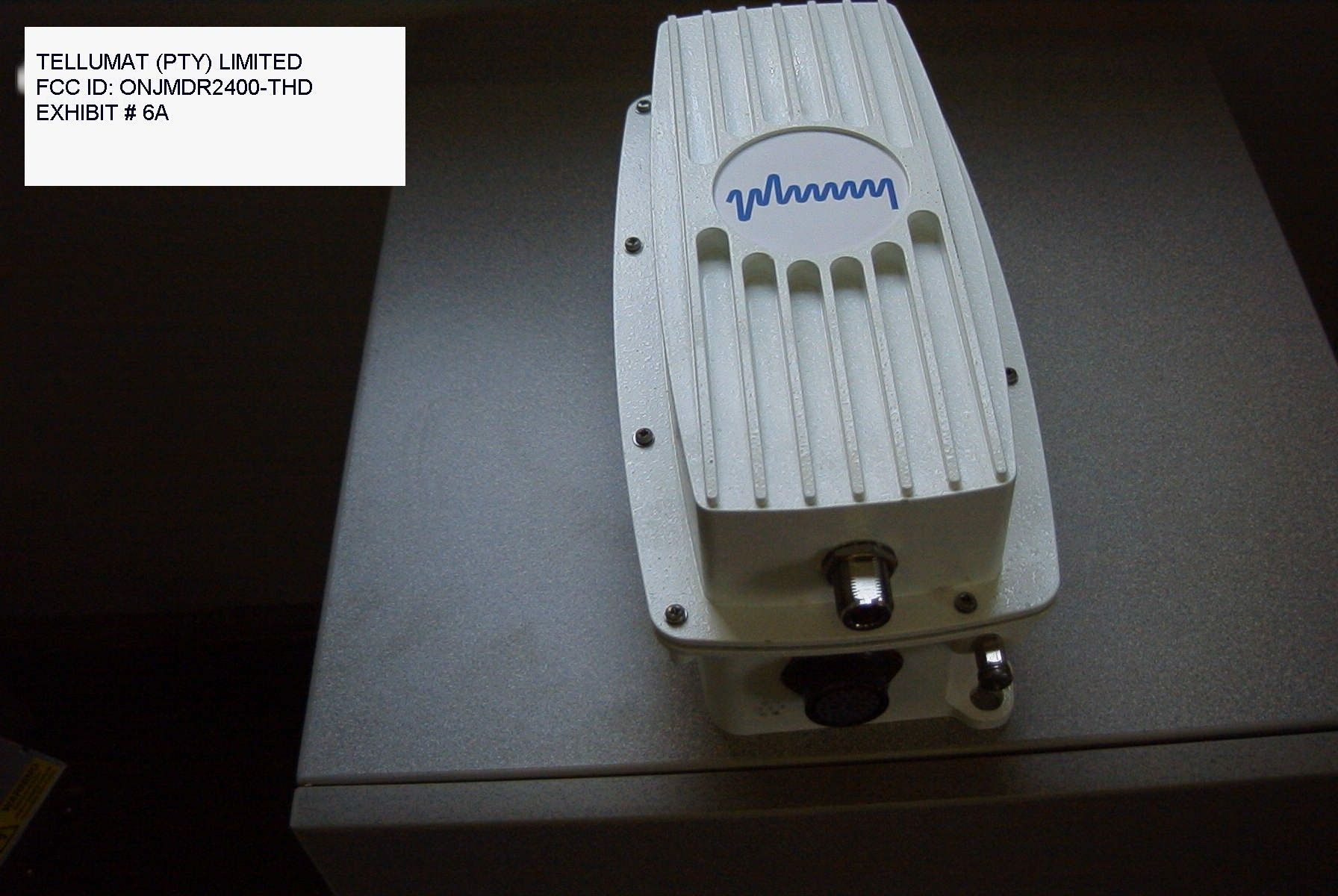
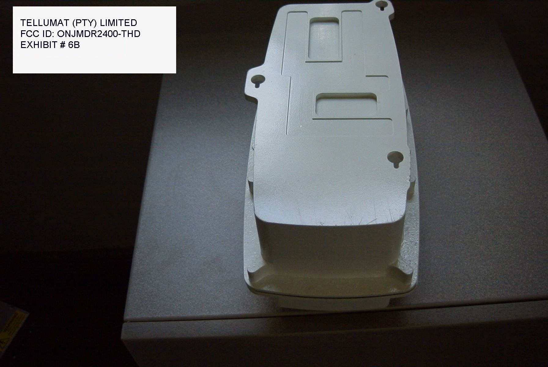
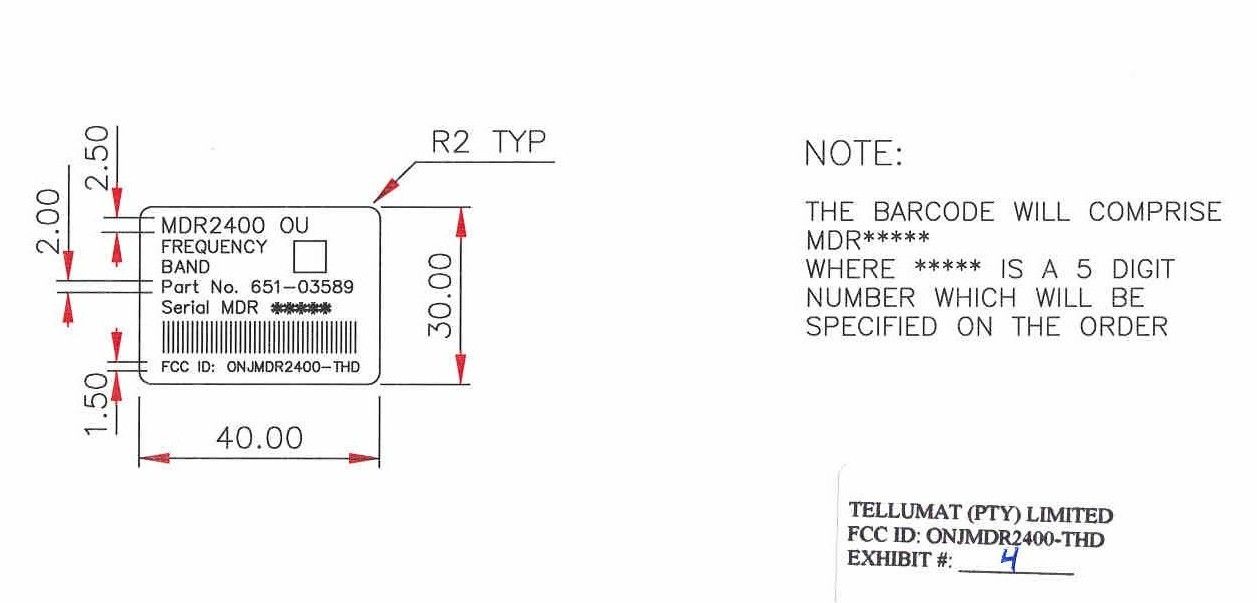
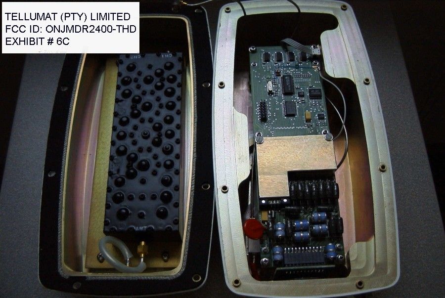
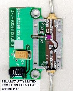
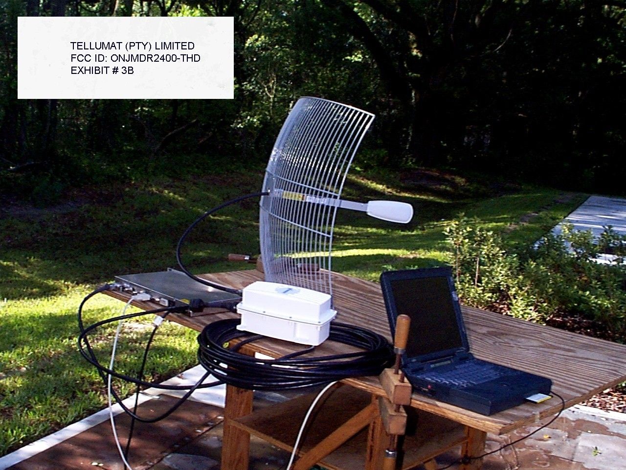
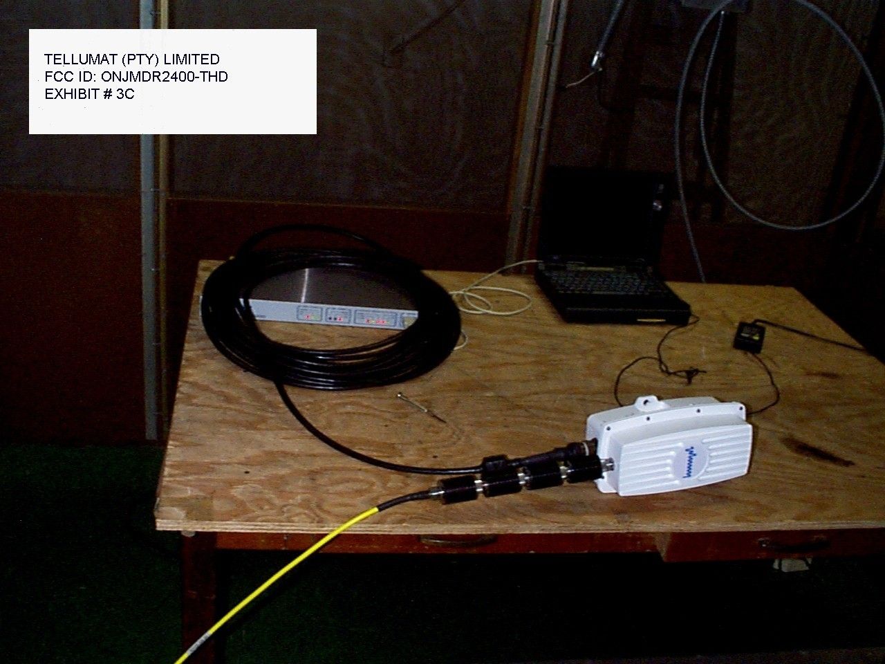
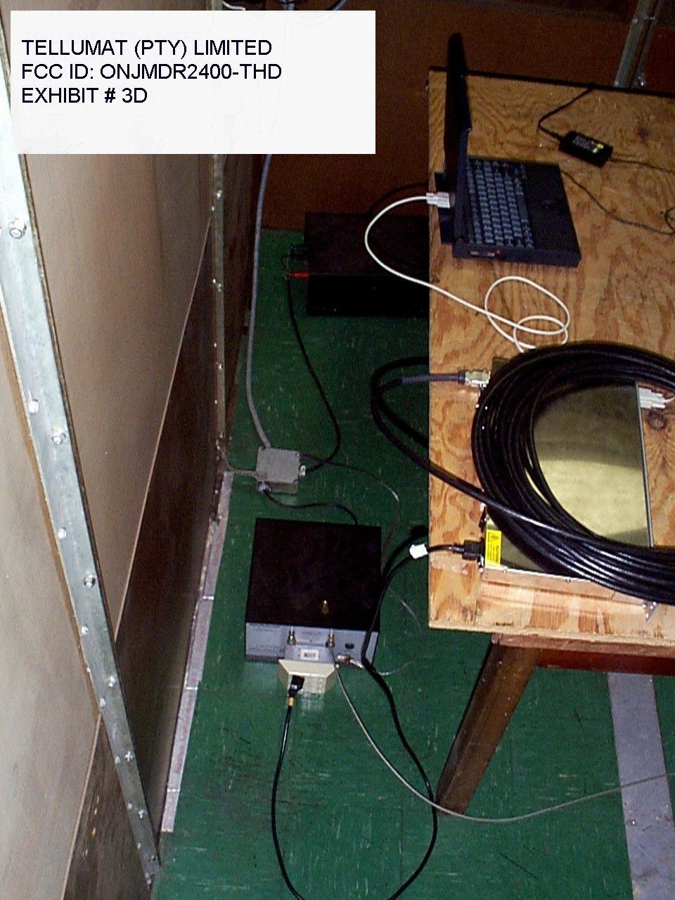
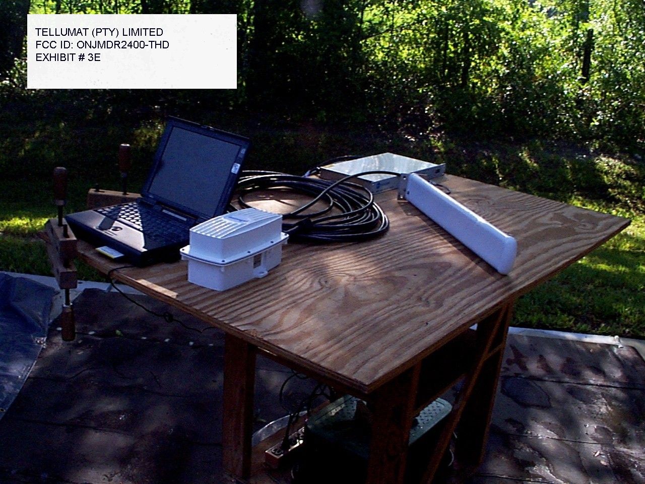
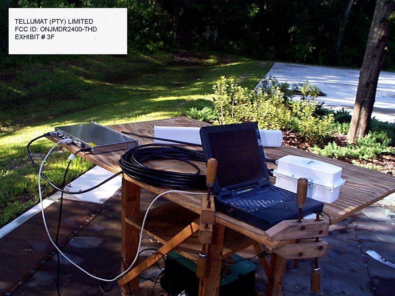
TABLE OF CONTENTS LIST APPLICANT: TELLUMAT(PTY) LIMITED. FCC ID: ONJMDR2400-THD TEST REPORT CONTAINING: PAGE 1.......LETTER ABOUT CONFIDENTIALITY PAGE 2.......LETTER OF EXPLANATION PAGE 3.......TEST PROCEDURE PAGE 4.......BLOCK DIAGRAM OF TEST SET UP PAGE 5.......CIRCUIT DESCRIPTION PAGE 6.......15.247(a)(2) 6.0dB BANDWIDTH & POWER OUTPUT PAGE 7.......15.247(c) ANTENNA CONDUCTED SPURIOUS PAGE 8-9.....15.247(c) RADIATED SPURIOUS EMISSIONS PAGE 10.......METHOD OF MEASURING RADIATED SPURIOUS EMISSIONS PAGE 11.......15.247(d) POWER SPECTRAL DENSITY PAGE 12.......PROCESSING GAIN(FROM ATT) PAGE 13.......POWER LINE CONDUCTED SPURIOUS EMISSIONS EXHIBITS CONTAINING: EXHIBIT 1A........POWER OF ATTORNEY LETTER EXHIBIT 1B........PROFESSIONAL INSTALLATION LTTER EXHIBIT 1C........CONFIDENTIALITY LETTER EXHIBIT 2.........PERMISSION LTTER FROM AIRONET EXHIBIT 3A-F......TEST SET UP PHOTOGRAPHS EXHIBIT 4.........FCC ID LABEL SAMPLE EXHIBIT 5.........FCC ID LABEL LOCATION EXHIBIT 6A........EXTERNAL FRONT VIEW PHOTOGRAPH EXHIBIT 6B........EXTERNAL REAR VIEW PHOTOGRAPH EXHIBIT 6C........INTERNAL COMPONENT SIDE PHOTOGRAPH EXHIBIT 6D-6E.....INTERNAL CHASSIS VIEW PHOTOGRAPHS EXHIBIT 6F-6H.....INTERNAL COMPONENT SIDE - PART OF RF PORTION EXHIBIT 7A-7C.....BLOCK DIAGRAMS EXHIBIT 8.........USER'S MANUAL EXHIBIT 9A-9B.....BANDWIDTH PLOTS EXHIBIT 10A-B.....SPECTRAL DENSITY PLOTS EXHIBIT 11A-B.....PLOTS OF POWER LINE CONDUCTED EMISSIONS APPLICANT: TELLUMAT(PTY) LIMITED. FCC ID: ONJMDR2400-THD REPORT #: F:\CUS\T\TELLUMAT\TEL366A9\TEL366A9.RPT DATE: AUGUST 19, 1999 TABLE OF CONTENTS LIST AUGUST 19, 1999 Federal Communications Commission Authorization and Evaluation Division 7435 Oakland Mills Road Columbia, MD 21046 SUBJECT: TELLUMAT(PTY) LIMITED. FCC ID: ONJMDR2400-THD To Whom It May Concern: This will serve as a request for confidentiality for the schemat- ics for the radio. The schematics will be sent directly from the manufacturer to the FCC upon request. Once the review of the application is complete and the schematics are no longer needed, they must be returned to the manufacturer, where they were sent from. Should you have any questions or require any further information with regards to this, please feel free to contact me. Sincerely, S. S. Sanders SSS/sh Encl. APPLICANT: TELLUMAT(PTY) LIMITED. FCCID: ONJMDR2400-THD REPORT #: F:\CUS\T\TELLUMAT\TEL366A9\TEL366A9.RPT DATE: AUGUST 19, 1999 PAGE #: 1 AUGUST 19, 1999 Federal Communications Commission Authorization and Evaluation Division 7435 Oakland Mills Road Columbia, MD 21046 SUBJECT: TELLUMAT(PTY) LIMITED. FCCID: ONJMDR2400-THD To Whom It May Concern: Attached you will find an application for a direct sequence spread spectrum assembly that is intended to be professionally installed. This unit will only be installed by authorized dealers that have been trained at the manufacturer's facilities. The model only operates in two(2) bands of frequencies, 2.411 to 2.430 GHz and 2.472 to 2.554 GHz and only comes in two configura- tions; 1. Yagi antenna(Long pointed white) 2. Parabolic Antenna. The user manuel will have the following statement in it; "WARNING! ALL PERSONNEL SHOULD STAY AT LEAST 1 METER(3.5') FROM ANTENNA TO AVOID EXPOSURE TO POSSIBLE MICROWAVE ENERGY." The antenna is intended to use outside. Sincerely, S. S. Sanders SSS/sh Encl. APPLICANT: TELLUMAT(PTY) LIMITED. FCCID: ONJMDR2400-THD REPORT #: F:\CUS\T\TELLUMAT\TEL366A9\TEL366A9.RPT DATE: AUGUST 19, 1999 PAGE #: 2 TEST EQUIPMENT LIST 1. Spectrum Analyzer: Hewlett Packard 8566B - Opt 462, w/ preselector 85685A, & Quasi-Peak Adapter HP 8565OA, & HP 8449B - OPT H02 Cal. 7/6/99 2. Signal Generator, Hewlett Packard 8640B, cal. 10/1/98 3. Signal Generator, HP 8614A Serial No.2015A07428 cal. 5/27/99 3. Eaton Biconnical Antenna Model 94455-1 20-200 MHz Serial No. 0997 Cal. 10/30/98 4. Electro-Metric Dipole Kit, 20-1000 MHz, Model TDA-30 10/31/98 5. Electro-Metric Horn 1-18 GHz, Model RGA-180, Cal. 10/30/98 6. Electro-Metric Antennas Model TDA-30/1-4,Cal. 10/15/98 7. Electro-Metric Line Impedance Stabilization Network Model No. EM-7821, Serial No. 101; 100KHz-30MHz 50uH. Cal.11/19/98 8. Electro-Metric Line Impedance Stabilization Network Model No. EM-7820, Serial No. 2682; 10KHz-30MHz 50uH. Cal. 11/19/98 9. Special low loss cable was used above 1 GHz 10. Tenney Temperature Chamber TEST PROCEDURE GENERAL: This report shall NOT be reproduced except in full without the written approval of TIMCO ENGINEERING, INC. Shielded interface cables were used in all cases except for cables connecting to the telephone line and the power cords. A test program was run which simulated a normal data transmission on a network. POWER LINE CONDUCTED INTERFERENCE: The procedure used was ANSI STAN- DARD C63.4-1992 using a 50uH LISN. Both lines were observed. The bandwidth of the spectrum analyzer was 10kHz with an appro- priate sweep speed. The ambient temperature of the UUT was 76oF with a humidity of 55%. BANDWIDTH 6.0dB: The measurements were made withe the spectrum analyz- er's resolution bandwidth(RBW)=100KHz and the video bandwidth(VBW) =300KHz and the span set as shown on plot. POWER OUTPUT: The RF power output was measured at the antenna feed point using a peak power meter. ANTENNA CONDUCTED EMISSIONS: The RBW=100KHz, VBW=300KHz and the span set to 100MHz and the spectrum was scanned from 30MHz to the 10th Harmonic of the fundamental. RADIATION INTERFERENCE: The test procedure used was ANSI STANDARD C63.4-1992 using a HEWLETT PACKARD spectrum analyzer with a prese- lector. The bandwidth(RBW) of the spectrum analyzer was 100kHz up to 1GHz and 1.0MHz above 1GHz with an appropriate sweep speed. The VBW above 1.0GHz was = 10Hz. The analyzer was calibrated in dB above a microvolt at the output of the antenna. The ambient temperature of the UUT was 89oF with a humidity of 86%. FCCID: ONJMDR2400-THD REPORT #: F:\CUS\T\TELLUMAT\TEL366A9\TEL366A9.RPT DATE: AUGUST 19, 1999 PAGE #: 3 /---------\ /---------\ /---------\ | OUTDOOR | Custom Cab…
Text truncated - open the document above for the full version.
Test Report
15.247(c) &15.109(b) Field_strength_of_spurious_emissions: REQUIREMENTS: Emissions that fall in the restricted bands (15.205) must be less than 54dBuV/m otherwise the spurious and harmonics must be attenuated by at least 20dB. TEST DATA: PEAK EMISSION METER COAX FIELD FCC FREQUENCY READING LOSS ACF STRENGTH LIMIT MARGIN MHz @ 3m dBuV dB dB dBuV/m dB dB ANT. YAGI ANTENNA: ANTENNA GAIN 17dBi 2413.00 65.60 1.09 29.03 95.72 0.0 0.0 V 4824.00R 14.90 1.45 33.93 50.28 54.00 3.72 V 7237.00 <2.80 1.82 36.64 41.26 54.00 12.74 V 9650.00 <1.00 2.11 38.60 41.71 54.00 12.29 V 2429.00 64.10 1.09 29.07 94.26 0.0 0.0 V 2483.50R 14.60 1.10 29.21 44.91 54.00 9.09 V 4858.00R 15.40 1.46 33.97 50.83 54.00 3.17 V 2455.00 64.10 1.10 29.14 94.34 0.0 0.0 V 2483.50R 15.60 1.10 29.21 45.91 54.00 8.09 V 4910.00R 9.20 1.47 34.02 44.69 54.00 9.31 V 7365.00R <2.90 1.84 36.79 41.52 54.00 12.48 V 9820.00 <0.60 2.13 38.71 41.44 54.00 12.56 H PARABOLIC ANTENNA: 24dBi 2413.00 68.40 1.09 29.03 98.52 0.0 0.0 V 4824.00R 15.90 1.45 33.93 51.28 54.00 2.72 V 7237.00 <1.90 1.82 36.64 40.36 54.00 13.64 V 2429.00 67.50 1.09 29.07 97.66 0.0 0.0 V 2483.50R 17.90 1.10 29.21 48.21 54.00 5.79 V 4858.00R 17.20 1.46 33.97 52.63 54.00 1.37 V 2455.00 66.90 1.10 29.14 97.14 0.0 0.0 V 2483.50R 16.60 1.10 29.21 46.91 54.00 7.09 V 4910.00R 11.10 1.47 34.02 46.59 54.00 7.41 V NOTE: ATTENUATION = PEAK CARRIER LEVEL - PEAK LEVEL OF HARMONIC MARGIN = 54dBuv/M - PEAK LEVEL OF HARMONIC APPLICANT: TELLUMAT (PTY) LIMITED. FCC ID: ONJMDR2400-THD REPORT #: T:\CUS\T\TELLUMAT\TEL366A9\RAD91028 DATE: 28 Oct. 1999 PAGE #: 8 METHOD OF MEASUREMENT: The procedure used was ANSI STANDARD C63.4-1992 except the spread spectrum portion was connected to its custom antenna at a height of 1.5 meters.The spectrum was scanned from 30MHz to at least the tenth harmonic of the fundamental. Above 1.0GHz the RBW was 1.0MHz and the VBW was 1.0MHz. Measurements were made at the open field test site of TIMCO ENGINEERING INC. located at 6051 N.W. 19th LANE, GAINESVILLE, FL 32605. 2.993(a)(b) 2.993(a)(b) Continued Field_strength_of_spurious_emissions: Method of Measuring Radiated Spurious Emissions Hewlett Packard Spectrum Analyzer HP8566A /-----------\ /----------------\ /----\ | | | ANTENNA & | | | | |TRANSMITTER|-------|COAX ASSEMBLY | \-----| | | UNDER TEST| | | | | \-----------/ \----------------/ \----/ ||| ||| | |? 3.0 meters--?| | | Tuned, Calibrated | Antenna which may /--------------\ be raised from 4 | | to 20' above ground |POWER SUPPLY | and changed | | in polarization \--------------/ Equipment placed 4' above ground on a rotatable platform. APPLICANT: TELLUMAT (PTY) LIMITED. FCCID: ONJMDR2400-THD REPORT #: T:\CUS\T\TELLUMAT\TEL366A9\RAD91028 DATE: 28 Oct. 1999 PAGE #: 9
Test Report
Product Name : R200 (025-1A) FCC ID: LOZ025-1A Name of Test : Processing Gain FCC Part 15.247 (e) specific The processing gain of a direct sequence system shall be at least 10dB. Guidance on measurement by FCC The processing gain may be measured using a CW jamming margin method. The tests consists of stepping a signal generator in 50kHz increments across the pass band of the system. At each point, the generator level required to produce the recommended Bit Error Rate (10-5) is recorded. This is the jammer level. The output power of the transmitting unit is measured at the same point. The Jammer to Signal (J/S) is then calculated. Discard the 20% worst of the J/S data points. Total losses in a system including transmitter and receiver, should be assumed to be no more than 2dB. Therefore , processing gain = S/N+Mj+Lsys Where S/N= Signal to Noise ratio required at the output receiver for 10-5 error rate of an ideal receiver. Mj= Jammer to Signal ratio Lsys = System Losses (2dB max) Test Results For 2mb data rate S/N = 13dB: taken from Wireless Information Networks by Pahlavan & Levesque Mj = 2.9 dB: from test in lab (20% worst discarded) Lsys = 1.5 dB: system losses Processing gain at 2 mb is 13dB-2.9 dB+1.5 dB =10.7 For 1mb data rate S/N = 13dB: taken from Wireless Information Networks by Pahlavan & Levesque Mj = 3.0 dB: from test in lab (20% worst discarded) Lsys = 1.5 dB: system losses Processing gain at 1 mb is 13dB- 3.1 dB+1.5 dB =10.5 For 512 kb data rate S/N = 13dB: taken from Wireless Information Networks by Pahlavan & Levesque Mj = 3.0 dB: from test in lab (20% worst discarded) Lsys = 1.5 dB: system losses Processing gain at 512kb is 13dB- 2.8 dB+1.5 dB =10.8
Test Report
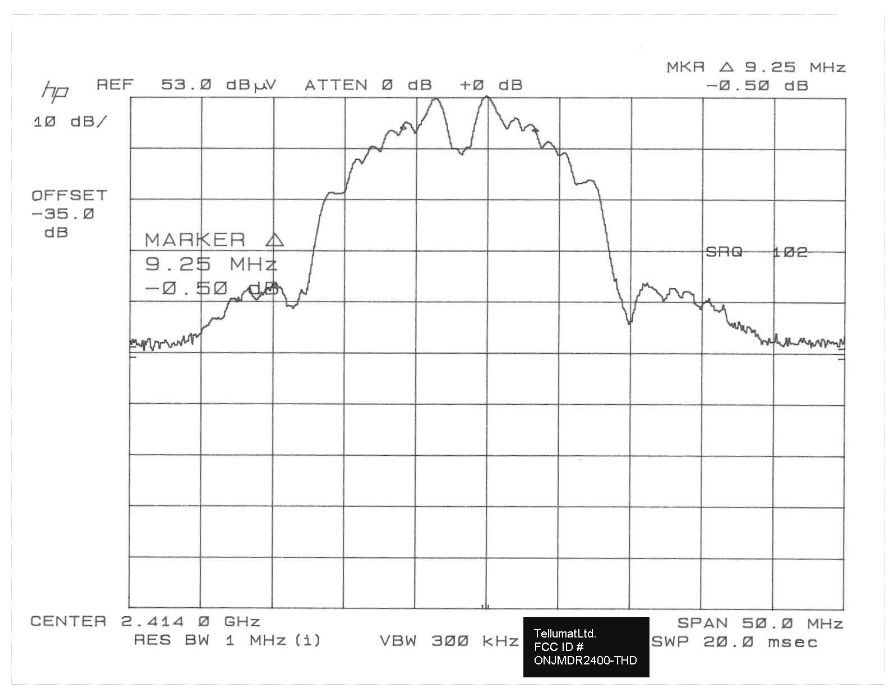
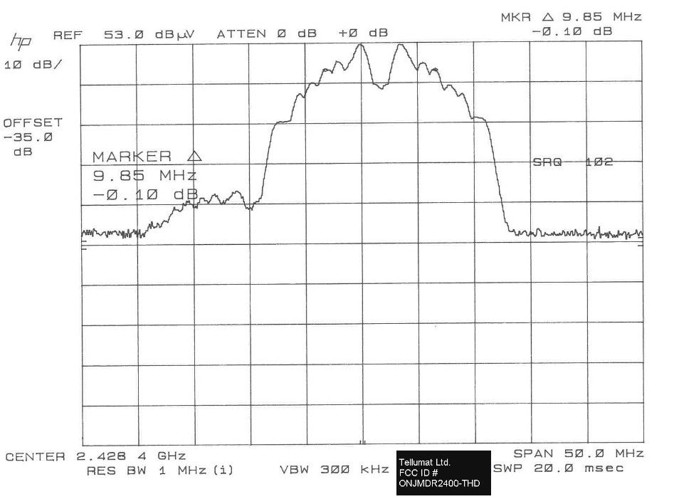
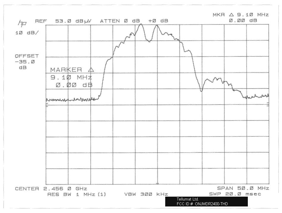
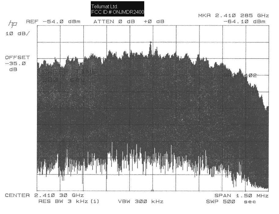
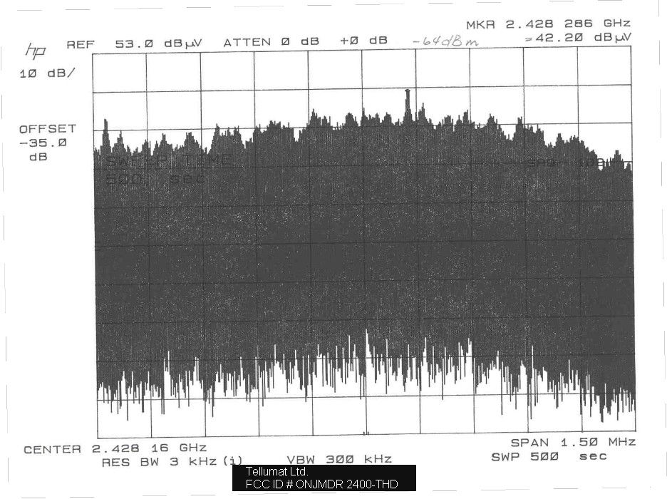
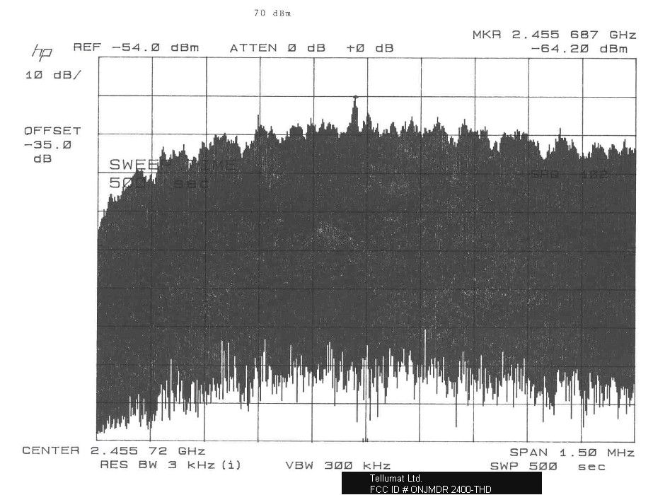
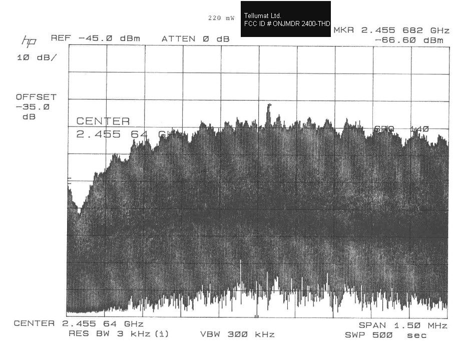
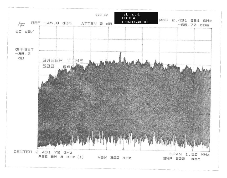
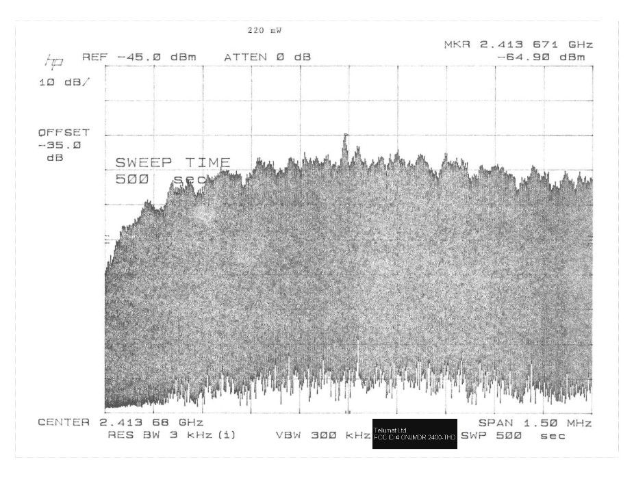
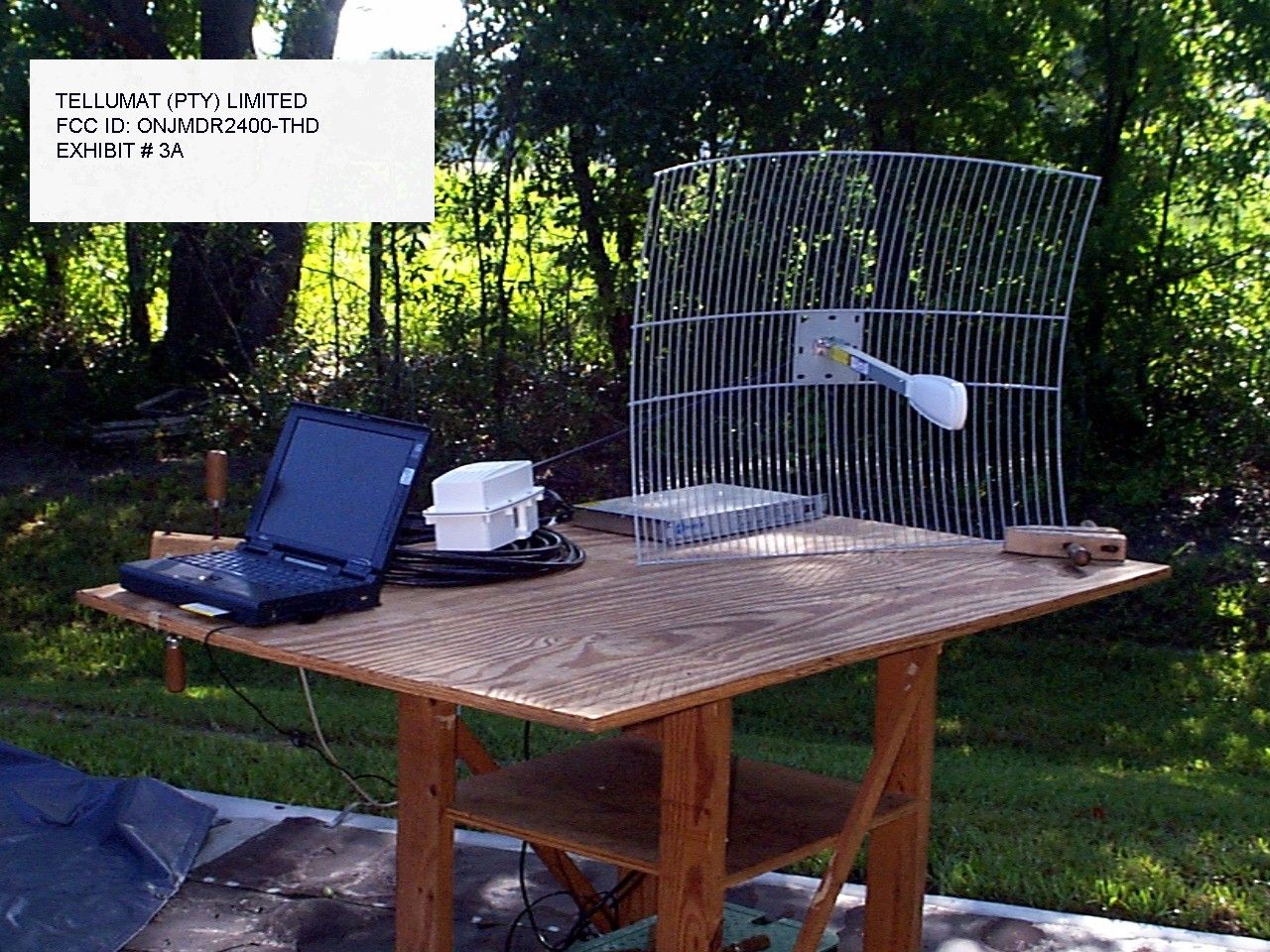
APPLICANT: TELLUMAT(PTY) LIMITED. FCC ID: ONJMDR2400-THD CIRCUIT DESCRIPTION: The ONJMDR2400-THD is a combination of the indoor unit the custom cable that connects the indoor unit to the outdoor unit, the outdoor unit and the antenna. A. Assembly #1 is with a Yagi Antenna(Long White). 17dBi Gain B. Assembly #2 is with a Parabolic Dish Antenna. 24dBi Gain PPLICANT: TELLUMAT(PTY) LIMITED. FCCID: ONJMDR2400-THD REPORT #: T:\CUS\T\TELLUMAT\TEL366Z9\TEL366Z9.RPT DATE: 3 Feb. 2000 PAGE #: 5 APPLICANT: TELLUMAT(PTY) LIMITED. FCC ID: ONJMDR2400-THD NAME OF TEST: 6.0dB BANDWIDTH RULES PART NUMBER: 15.247(a)(2) REQUIREMENTS: The 6.0dB bandwidth must be greater than 500KHz. MEASUREMENT: The 6.0dB bandwidth measured 9.25MHz @ 2414.0MHz and 9.85MHz @ 2428.4MHz and [email protected] MEASUREMENT DATA: See plot on the next page. NAME OF TEST: POWER OUTPUT RULES PART NUMBER: 15.247(b)1.0W or 30dBm 0.40W or 26dBm for an 18dBi Gain Antenna 0.250W or 24dBm for an 24dBi Gain Antenna MEASUREMENT: 220 mWatts for the Yagi Antenna 380 mWATTS for the Parabol…
Text truncated - open the document above for the full version.
Contact Information
Applicant
Ruth French(Product Compliance Manager)
Technical Contact
TIMCO ENGINEERING, INC.S.S. SANDERS
[email protected]888-472-2424
P.O. BOX 370 · NEWBERRY, Florida · United States
Non-Technical Contact
TIMCO ENGINEERING, INC.SHARON A HOFFMAN
[email protected]888-472-2424
Test Firm
Timco Engineering, Inc.Sid Sanders
Technical Specifications
| # | Rule Parts | Frequency Range | Power Output |
|---|---|---|---|
| 1 | 15C | 2.41 GHz - 2.46 GHz | 400.00 mW |
Other Applications from Aviat Networks
ONJ-3ECJ68B3E
Aug 12, 2003PTP Radio
Equipment Class
DTS - Digital Transmission System
ONJ-3ECJ68A4D
Jul 06, 2003Digital Radio
Equipment Class
DTS - Digital Transmission System
ONJ-MDR2400ET
Jun 19, 2002Digital Radio
Equipment Class
DSS - Part 15 Spread Spectrum Transmitter
ONJ-MDR5800ET
May 14, 2001Point to Point Spread Spectrum Transceiver
Equipment Class
DSS - Part 15 Spread Spectrum Transmitter
ONJMDR8500
May 01, 2001Point to Point Spread Spectrum Transceiver
Equipment Class
DSS - Part 15 Spread Spectrum Transmitter