ONJMDR2400-THCSpread Spectrum Assembly T1 Antenna System
Aviat Networks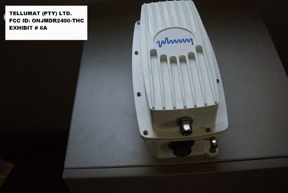
Click to zoom
Application Details
- Equipment Class
- DSS - Part 15 Spread Spectrum Transmitter
- Date of Grant
- Mar 06, 2000
- Application Purpose
- Original Equipment
- Date of Application
- Dec 21, 1999
- Equipment Note
- Spread Spectrum Assembly T1 Antenna System
- Frequency Range
- 2412.00000000 - 2456.00000000
- Company
- Aviat Networks
- Country
- Singapore
Documents & Files
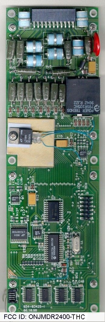
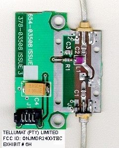
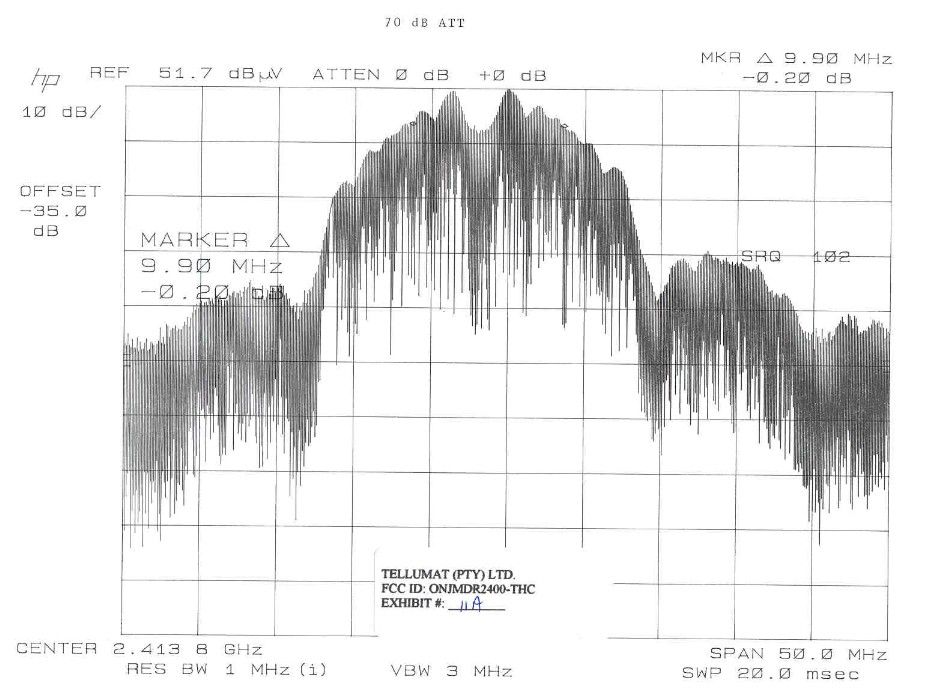
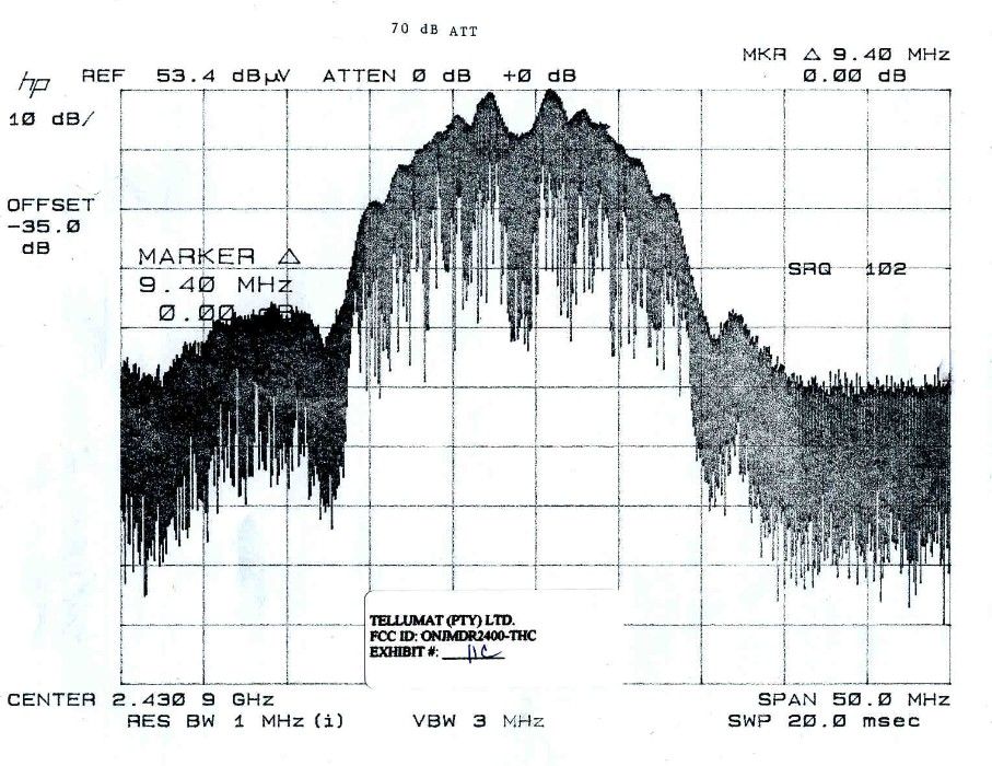
Document Text
Text extracted from the exhibit documents filed with the FCC. Open a document above to read the original.
Users Manual
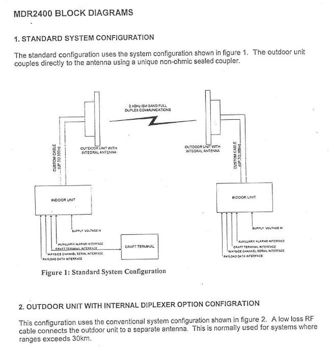
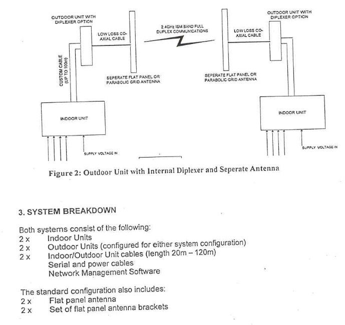
862-01545μLink System Manual Issue 1bPage i μμLink Digital Radio System Manual Publication Number: 862-01545 Issue 1b February 1999 Tellumat (Pty) Limited Reg. No. 96/000957/07 64/74 White Road, Retreat, 7945 P.O. Box 30451, Tokai, 7966 Telephone: +27 21 710-2911 Fax No. +27 21 710-2333 μLink System Manual862-01545 Page iiIssue 1b Federal Communications Commission Notice NOTE The equipment has been tested and found to comply with the limits for a Class A digital devices, pursuant to Part 15 of the FCC Rules. These limits are designed to provide reasonable protection against harmful interference when the equipment is operated in a commercial environment. This equipment generates, uses, and can radiate radio frequency energy and, if not installed and used in accordance with the instruction manual, may cause harmful interference to radio communications. Operation of this equipment in a residential area is likely to cause harmful interference in which case the user will be required to correct the interference at his own expense. The manufacturer is not responsible for any radio or TV interference caused by unauthorised modifications to this equipment. Such modifications could void the user's authority to operate the equipment. This device complies with Part 15 of the FCC Rules. Operation is subject to the following two conditions: (1) this device may not cause interference, and (2) this device must accept any interference, including interference that may cause undesired operation of the device. This equipment must be professionally installed. PER FCC rules 15.247 (b)(4) WARNING! ALL PERSONNEL SHOULD STAY AT LEAST 1 METER (3.5') FROM THE ANTENNA TO AVOID EXPOSURE TO POSSIBLE MICROWAVE ENERGY. 862-01545μLink System Manual Issue 1bPage iii Document Issue Status When an issue status of this manual changes, the record below must be completed and initialled. Page No. Issue Status Authority (ECN No.) Page No. Issue Status Authority (ECN No.) 1 - 781 1 - 821b μLink System Manual862-01545 Page ivIssue 1b Table of Contents Page Chapter 1: Purpose and Planning............................................................1 Introduction to Chapter 1....................................................................1 μLink Product Family.........................................................................1 Role and Purpose................................................................................1 System Description......................................................................................2 System Overview................................................................................2 Features..............................................................................................2 System Configuration Options............................................................5 Interface Definitions...........................................................................6 Planning Information..........................................................................7 Site Evaluation...............................................................................7 Multipath Effects...........................................................................8 Installation Information......................................................................9 General Information.......................................................................9 Indoor Unit....................................................................................9 Outdoor Unit and Antenna.............................................................9 Operational Capabilities...................................................................10 Maintenance Features.......................................................................11 Built-in Test Features...................................................................11 System Specifications.......................................................................12 Performance Characteristics.........................................................12 Data Transmission Characteristics...............................................12 Transmitter Characteristics..........................................................13 Receiver Characteristics...............................................................13 Wayside Service Channel.............................................................14 Auxiliary/Alarm Interfaces...........................................................14 Power Supply Characteristics.......................................................15 Controls and Displays..................................................................15 Antenna Characteristics (μLink -T)..............................................16 Equipment Status Monitoring......................................................17 Mechanical Characteristics..........................................................18 Environmental Characteristics.....................................................18 Frequency Band Plan........................................................................19 862-01545μLink System Manual Issue 1bPage v Chapter 2: Installation...........................................................................21 Introduction to Chapter 2.................................................................21 Site Requirements............................................................................21 Parts and Accessories Supplied for Installation.................................22 Customer Furnished Tools and Equipment.......................................23 Installation Overview.......................................................................24 Antenna Installation....................................................................24 Outdoor Unit Installation.............................................................26 Indoor Unit Installation...............................................................29 Interconnection Cable Installation.............…
Text truncated - open the document above for the full version.
Cover Letter(s)
Tellumat (Pty) Limited 64-74 White Road, Retreat 7945 P.O. Box 30451, Tokai 7966 South Africa DIRECTORS: Dr. J.A. Temple (Chairman), L.C. Jones (Managing), P.B. Hobbs, C.J. Meintjes R.J. Shaw, Dr. S. Sibisi, J. de V. van Zyl, M. Higgins, K.A. Alborough (Alt), J.W. Grobler (Alt), M. D. Chewins (Alt) Registration Number: 96/00957/07 Tel: +27 (21) 710-2911 Fax: +27 (21) 710-2360 22 September 1999 Federal Communications Commission Authorisation & Evaluation Division 7435 Oakland Mills Road Columbia, Maryland 21046 To Whom It May Concern: Tellumat (Pty) Limited hereby requests that all circuit diagrams submitted to the FCC be treated with the strictest confidentiality. All information is proprietary and the sole property of Tellumat (Pty) Limited, and as such should not be made available to any third party Sincerely Tellumat (Pty) Limited pp S.J. Fouche Manager – Tellumat Microwave & RF Products
ID Label/Location Info
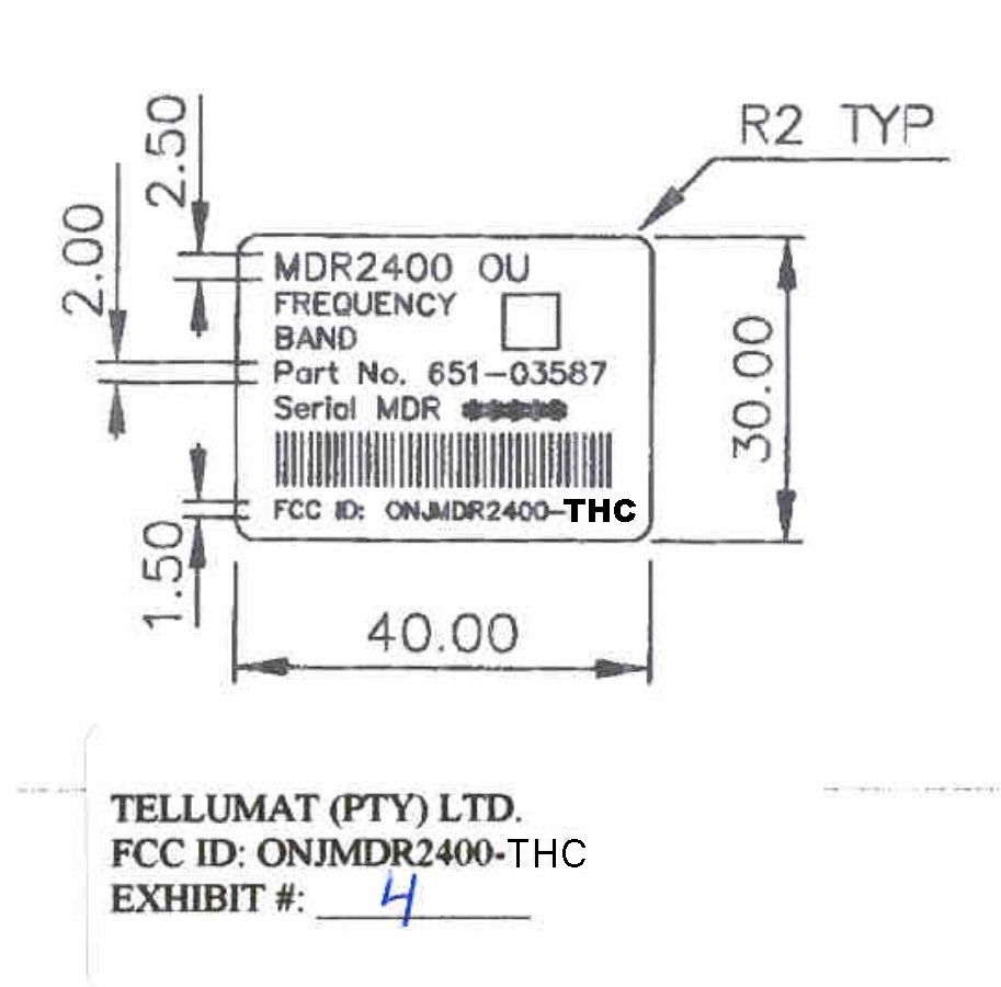
MDR2400 OU FREQUENCY BAND Part No. 651-03587 Serial MDR ∗∗∗∗∗ FCC ID: ONJMDR2400-THC TELLUMAT (PTY) LTD. FCC ID: ONJMDR2400-THC EXHIBIT # 4
Test Report
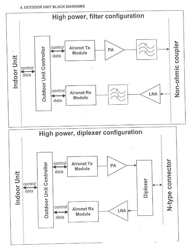
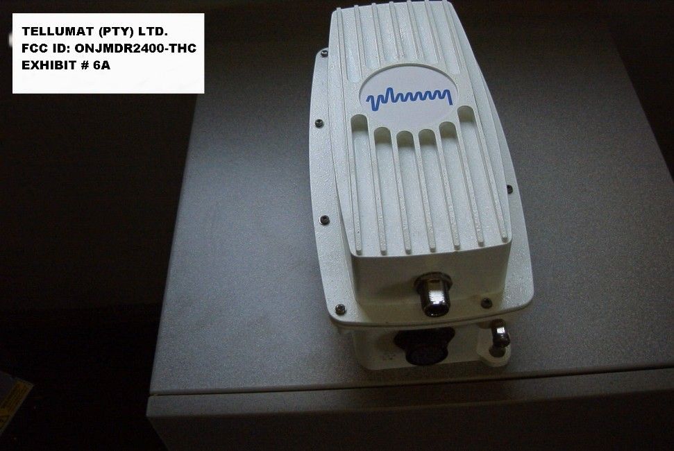
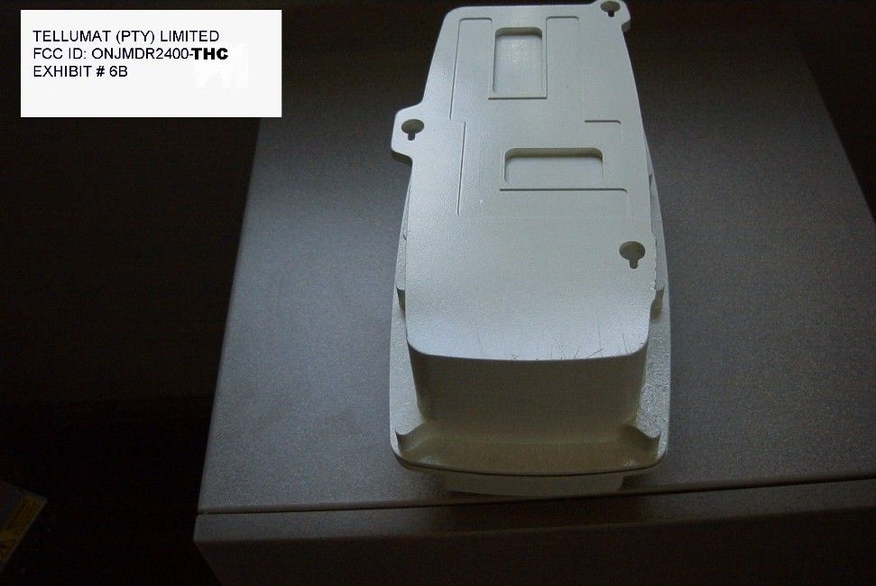
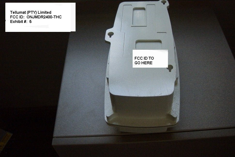
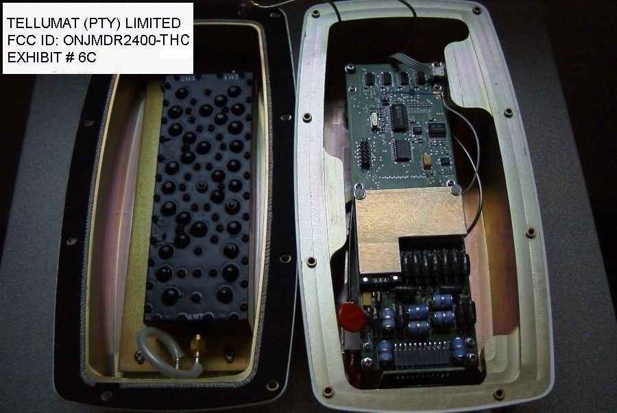
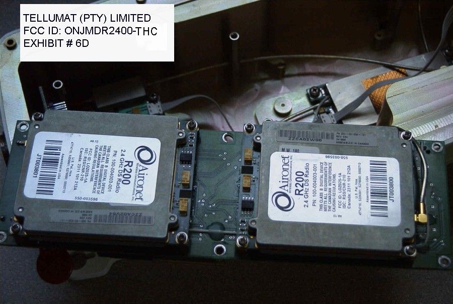
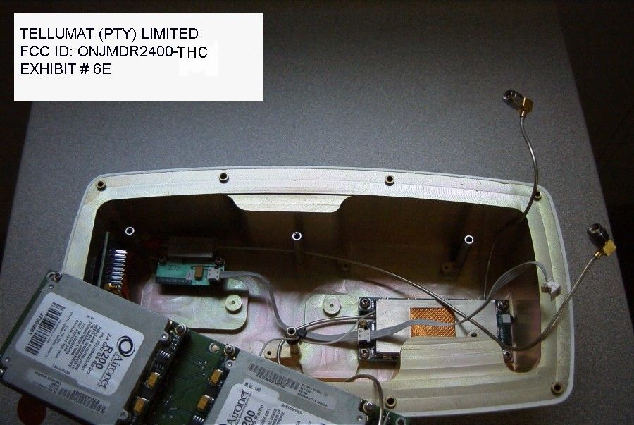
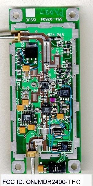
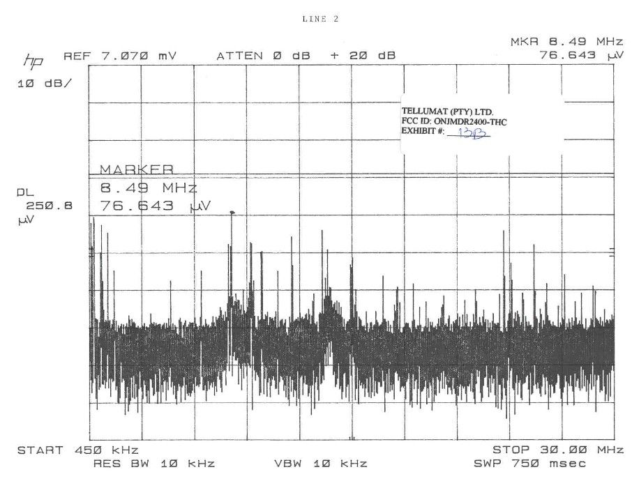
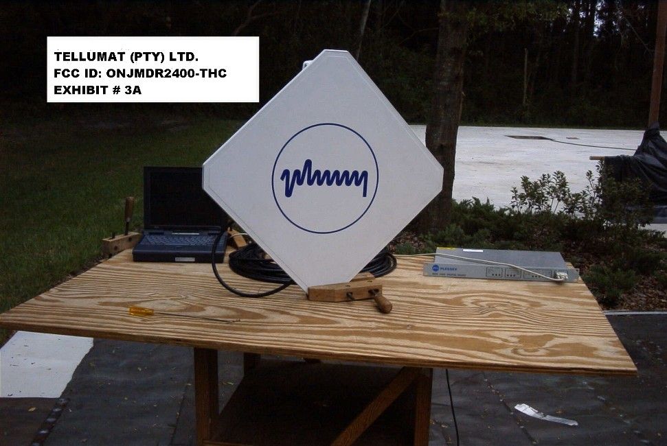
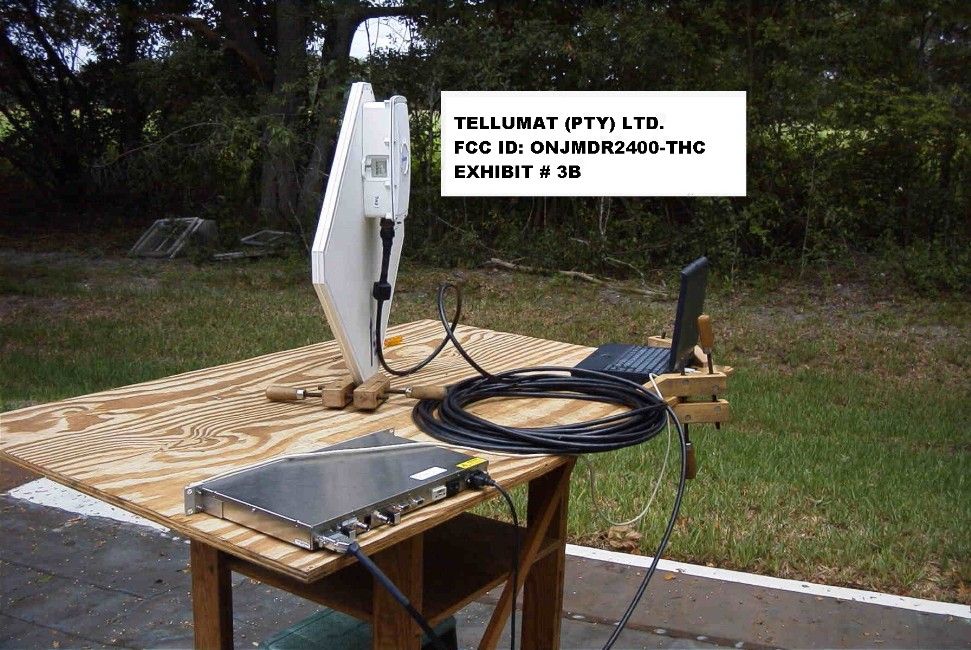
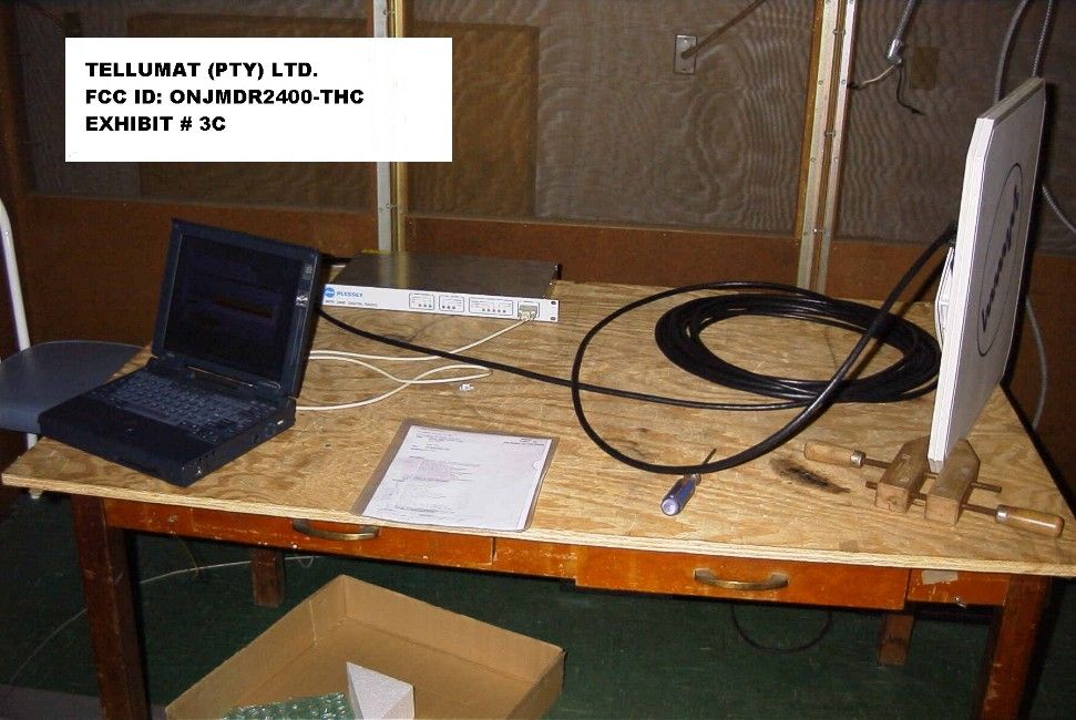
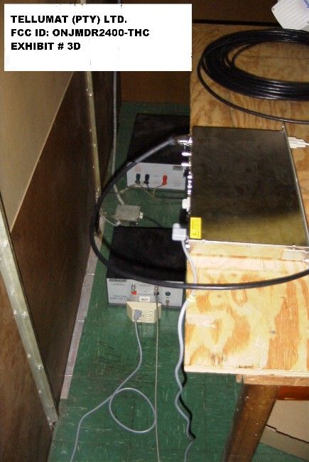
TABLE OF CONTENTS LIST APPLICANT: TELLUMAT (PTY) LIMITED. FCC ID: ONJMDR2400-THC TEST REPORT CONTAINING: PAGE 1.......LETTER ABOUT CONFIDENTIALITY & PROFESSIONAL INSTALLATION PAGE 2.......LIST OF TEST EQUIPMENT AND TEST PROCEDURE PAGE 3.......TEST PROCEDURE CONTD & BLOCK DIAGRAM OF TEST SET UP AND CIRCUIT DESCRIPTION PAGE 4.......15.247(a)(2) 6.0dB BANDWIDTH & POWER OUTPUT PAGE 5.......15.247(c) ANTENNA CONDUCTED SPURIOUS PAGE 6.......15.247(c) RADIATED SPURIOUS EMISSIONS PAGE 7.......METHOD OF MEASURING RADIATED SPURIOUS EMISSIONS PAGE 8.......15.247(d) POWER SPECTRAL DENSITY PAGE 9.......PROCESSING GAIN (FROM ATT) PAGE 10.......POWER LINE CONDUCTED SPURIOUS EMISSIONS EXHIBITS CONTAINING: EXHIBIT 1A........POWER OF ATTORNEY LETTER EXHIBIT 1B........CONFIDENTIALITY LETTER EXHIBIT 2.........PERMISSION LETTER FROM AERONAUT EXHIBIT 3A-3B.....RADIATED EMISSIONS TEST SET UP PHOTOGRAPHS EXHIBIT 3C-3D.....POWERLINE CONDUCTED TEST SET UP PHOTOGRAPHS EXHIBIT 4.........FCC ID LABEL SAMPLE EXHIBIT 5.........FCC ID LABEL LOCATION EXHIBIT 6A........EXTERNAL FRONT VIEW PHOTOGRAPH EXHIBIT 6B........EXTERNAL REAR VIEW PHOTOGRAPH EXHIBIT 6C........INTERNAL CHASSIS VIEW - COMPONENT SIDE EXHIBIT 6D-6E.....INTERNAL CHASSIS VIEW - BOARDS COVERED EXHIBIT 6F........INTERNAL COMPONENT SIDE PHOTO EXHIBIT 6G........INTERNAL SOLDER SIDE PHOTO EXHIBIT 6H........INTERNAL COMPONENT SIDE PHOTO - SMALL BOARD EXHIBIT 7A-7C.....BLOCK DIAGRAMS EXHIBIT 8A-8E.....PROCESSING GAIN EXHIBIT 9.........USER'S MANUAL EXHIBIT 10........THEORY OF OPERATION EXHIBIT 11A-C.....BANDWIDTH PLOTS EXHIBIT 12A-C.....SPECTRAL DENSITY PLOTS EHXIBIT 13A-B.....PLOTS OF POWER LINE CONDUCTED EMISSIONS APPLICANT: TELLUMAT (PTY) LIMITED. FCC ID: ONJMDR2400-THC REPORT #: T:\CUS\T\TELLUMAT\TEL464U9\TEL464A9.RPT DATE: NOVEMBER 15, 1999 TABLE OF CONTENTS LIST NOVEMBER 15, 1999 Federal Communications Commission Authorization and Evaluation Division 7435 Oakland Mills Road Columbia, MD 21046 SUBJECT: TELLUMAT (PTY) LIMITED. FCC ID: ONJMDR2400-THC To Whom It May Concern: This will serve as a request for confidentiality for the schemat- ics for the radio. The schematics will be sent directly from the manufacturer to the FCC upon request. Once the review of the application is complete and the schematics are no longer needed, they must be returned to the manufacturer, where they were sent from. Attached as Exhibit 1B you will find a request for approval as a professionally installed equipment. Should you have any questions or require any further information with regards to this, please feel free to contact me. Sincerely, S. S. Sanders SSS/sh Encl. APPLICANT: TELLUMAT (PTY) LIMITED. FCCID: ONJMDR2400-THC REPORT #: T:\CUS\T\TELLUMAT\TEL464U9\TEL464A9.RPT DATE: NOVEMBER 15, 1999 PAGE #: 1 TEST EQUIPMENT LIST 1. Spectrum Analyzer: HP 8566B-Opt 462, S/N 3138A07786, w/ preselector HP 85685A, S/N 3221A01400, Quasi-Peak Adapter HP 8565OA, S/N 3303A01690 & Preamplifier HP 8449B-OPT H02, S/N 3008A00372 Cal. 10/17/99 2. Signal Generator: HP 8640B, S/N 2308A21464 Cal. 9/23/99 3. Signal Generator: HP 8614A, S/N 2015A07428 Cal. 5/29/99 4. Passive Loop Antenna: EMCO Model 6512, 9KHz to 30MHz, S/N 9706-1211 Cal. 6/23/97 5. Biconnical Antenna: Eaton Model 94455-1, S/N 1057 6. Log-Periodic Antenna: Electro-Metrics Model EM-6950, S/N 632 7. Dipole Antenna Kit: Electro-Metrics Model TDA-30/1-4, S/N 153 Cal. 11/24/99 8. Double-Ridged Horn Antenna: Electro-Metrics Model RGA-180, 1-18 GHz, S/N 2319 Cal. 4/27/99 9. Horn 40-60GHz: ATM Part #19-443-6R 10. Line Impedance Stabilization Network: Electro-Metrics Model FCC-25/2, S/N 2512 Cal. 11/18/99 11. Line Impedance Stabilization Network: Electro-Metrics Model ANS-25/2, S/N 2604 Cal. 11/30/99 12. Line Impedance Stabilization Network: Electro-Metrics Model EM-7820, S/N 2682 Cal. 12/1/99 13. Line Impedance Stabilization Network: Electro-Metrics Model EM-7821, S/N 101 Cal. 12/1/99 14. Temperature Chamber: Tenney Engineering Model TTRC, S/N 11717-7 15. AC Voltmeter: HP Model 400FL, S/N 2213A14499 Cal. 9/21/99 16. Digital Multimeter: Fluke Model 8012A, S/N 4810047 Cal 9/21/99 17. Digital Multimeter: Fluke Model 77, S/N 43850817 Cal 9/21/99 18. Oscilloscope: Tektronix Model 2230, S/N 300572 Cal 9/23/99 19. Frequency Counter: HP Model 5385A, S/N 3242A07460 Cal 10/6/99 TEST PROCEDURE GENERAL: This report shall NOT be reproduced except in full without the written approval of TIMCO ENGINEERING, INC. Shielded interface cables were used in all cases except for cables connecting to the telephone line and the power cords. A test program was run which simulated a normal data transmission on a network. POWER LINE CONDUCTED INTERFERENCE: The procedure used was ANSI STAN- DARD C63.4-1992 using a 50uH LISN. Both lines were observed. The bandwidth of the spectrum analyzer was 10kHz with an appro- priate sweep speed. The ambient temperature of the UUT was 76oF with a humidity of 55%. APPLICANT: TELLUMAT (PTY) LIMITED. FCCID: ONJMDR2400-THC REPORT #: T:\CUS\T\TELLUMAT\TEL464U9\TEL464A9.RPT DATE: NOVEMBER 15, 1999 PAGE #: 2 TEST PROCEDURE CONTINUED BANDWIDTH 6.0dB: The measurements were made with the spectrum analyz- er's resolution bandwidth(RBW)=1.0MHz and the video bandwidth(VBW) =3.0MHz and the span set as shown on plot. POWER OUTPUT: The RF power output was measured at the antenna feed point using a peak power meter. ANTENNA CONDUCTED EMISSIONS: The RBW=1.0MHz, VBW=3.0MHz and the span set to 100MHz and the spectrum was scanned from 30MHz to the 10th Harmonic of the fundamental. RADIATION INTERFERENCE: The test procedure used was ANSI STANDARD C63.4-1992 using a HEWLETT PACKARD spectrum analyzer with a prese- lector. The bandwidth(RBW) of the spectrum analyzer was 100kHz up to 1GHz and 1.0MHz above 1GHz with an appropriate sweep speed. The VBW above 1.0GHz was = 3.0MHz. The analyzer was calibrated in dB above a microvolt at the output of the antenna. The ambient temperature of the UUT was 57.3oF with a humidity of 44%. BLOCK DIAGRAM OF TEST SET UP /-----…
Text truncated - open the document above for the full version.
Test Report
Product Name : R200 (025-1A) FCC ID: LOZ025-1A Name of Test : Processing Gain FCC Part 15.247 (e) specific The processing gain of a direct sequence system shall be at least 10dB. Guidance on measurement by FCC The processing gain may be measured using a CW jamming margin method. The tests consists of stepping a signal generator in 50kHz increments across the pass band of the system. At each point, the generator level required to produce the recommended Bit Error Rate (10-5) is recorded. This is the jammer level. The output power of the transmitting unit is measured at the same point. The Jammer to Signal (J/S) is then calculated. Discard the 20% worst of the J/S data points. Total losses in a system including transmitter and receiver, should be assumed to be no more than 2dB. Therefore , processing gain = S/N+Mj+Lsys Where S/N= Signal to Noise ratio required at the output receiver for 10-5 error rate of an ideal receiver. Mj= Jammer to Signal ratio Lsys = System Losses (2dB max) Test Results For 2mb data rate S/N = 13dB: taken from Wireless Information Networks by Pahlavan & Levesque Mj = 2.9 dB: from test in lab (20% worst discarded) Lsys = 1.5 dB: system losses Processing gain at 2 mb is 13dB-2.9 dB+1.5 dB =10.7 For 1mb data rate S/N = 13dB: taken from Wireless Information Networks by Pahlavan & Levesque Mj = 3.0 dB: from test in lab (20% worst discarded) Lsys = 1.5 dB: system losses Processing gain at 1 mb is 13dB- 3.1 dB+1.5 dB =10.5 For 512 kb data rate S/N = 13dB: taken from Wireless Information Networks by Pahlavan & Levesque Mj = 3.0 dB: from test in lab (20% worst discarded) Lsys = 1.5 dB: system losses Processing gain at 512kb is 13dB- 2.8 dB+1.5 dB =10.8
Contact Information
Applicant
Ruth French(Product Compliance Manager)
Technical Contact
Timco Engineering Inc.S S Sanders
[email protected]888-472-2424
P O Box 370 · Newberry, Florida · United States
Non-Technical Contact
Timco Engineering Inc.Sharon A Hoffman
[email protected]888-472-2424
Test Firm
Timco Engineering, Inc.S Sanders
Technical Specifications
| # | Rule Parts | Frequency Range | Power Output |
|---|---|---|---|
| 1 | 15C | 2.41 GHz - 2.46 GHz | 330.00 mW |
Other Applications from Aviat Networks
ONJ-3ECJ68B3E
Aug 12, 2003PTP Radio
Equipment Class
DTS - Digital Transmission System
ONJ-3ECJ68A4D
Jul 06, 2003Digital Radio
Equipment Class
DTS - Digital Transmission System
ONJ-MDR2400ET
Jun 19, 2002Digital Radio
Equipment Class
DSS - Part 15 Spread Spectrum Transmitter
ONJ-MDR5800ET
May 14, 2001Point to Point Spread Spectrum Transceiver
Equipment Class
DSS - Part 15 Spread Spectrum Transmitter
ONJMDR8500
May 01, 2001Point to Point Spread Spectrum Transceiver
Equipment Class
DSS - Part 15 Spread Spectrum Transmitter