ONKARH-465GMRS Transceiver
Airtech Information & Communication Co., Ltd.
Click to zoom
Application Details
- Equipment Class
- TNF - Licensed Non-Broadcast Transmitter Held to Face
- Date of Grant
- Dec 11, 2000
- Application Purpose
- Original Equipment
- Date of Application
- Oct 03, 2000
- Equipment Note
- GMRS Transceiver
- Frequency Range
- 462.55000000 - 462.72500000
- Country
- South Korea
Documents & Files
Document Text
Text extracted from the exhibit documents filed with the FCC. Open a document above to read the original.
Users Manual
INDEXGENERAL FEATURES ....................................................................1 UNPACKING ......................................................................................2 GETTING READY ............................................................................2 DESCRIPTION ..................................................................................2 OPERATION ......................................................................................3 FUNCTION MODE ...........................................................................4 RECHARGING THE BATTERY ......................................................5 SPECIFICATIONS .............................................................................5 GENERAL FEATURESGeneral Features! Ultra compact design & size 115x53x28mm, 138g only ! 38 CTCSS ! Button Lock ! Scan & Priority Scan ! Beep on/off ! Talking range to 4 miles ! Transferable by cloning ! Clear voice transmission and reception ! Rugged construction UNPACKINGUnpack and check that all items have been enclosed.Packing contents: 1. Radio/Antenna, 2. Battery, 3. Belt clip, 4. Hand strap, 5. Charger, 6.User’s manual GETTING READY1. Installation, Remov al the Belt Clip Installation: align the belt clip with the plastic slots of backside of unit. Slide the belt clip onto the unit,pushing firmly until a click heard. Removal: hold up the belt clip release tab with fingernail or coin (or like instrument). While holding up the releasetab, slide the belt clip out and away from the unit. 2. Installation the Battery Pack Installation: turn off the radio. Unscrew the battery pack cover lock screw by rotating counterclockwise withcoin (or like instrument). Open the cover and insert thebattery pack in right position. Close the cover andscrew the cover lock screw. 3. Charging the Battery Before your starting operation, make sure the batteryis fully charged. (Refer to charging method next page) DESCRIPTION • power on/off button and indicate LED Push 0.5 second to turn power on, push 0.5 second againto turn power off. Indicate LED Red on Transmitting, charging Blinking Low battery alert Green on Receiving, recharging finished Blinking Different sub-tone when • external audio/microphone and adapter socket • antenna • speaker • PTT(push to talk) button• up/down button • function button • monitor button • LCD display panel• enter button • power on/off button and indicate LED• microphone receiving Red, green both on Abnormal charging • up/down button You can select the audio volume (0~15), the channel andthe function mode on or off with this button.• function button Press to go function mode (refer to next page).• monitor button Press to monitor. Holding down over 2 seconds keepsmonitoring on. Press monitor button again to stop.• enter button Press to finalize setting.• PTT(push to talk) button Hold down to transmit, release to receive.• LCD display panel • speaker • microphone Talk 5 • in distance during transmitting. • antenna • external audio/microphone and adapter so cket • belt clip release tab • battery pack cover • cover lock screw • belt clip • hand strap OPERATION 1. Power turn on/off and volume controlPress power on/off button • 0.5 second to turn power on, press 0.5 second again to power off. Press up/downbutton • to increase or reduce the audio volume ( 00 ~ 15 ). Holding down up/down button • makes to move fast. 2. TransmitChoose the channel as you desire. Hold down the PTTbutton • and talk to microphone • in 5 • distance. The LED • (power button) lights red on transmitting. Release the PTT button to stop transmitting. 3. ReceiveChoose the channel as you desire. The LED • lights green on receiving. In case the signal doesn’t match sub-tone,the green light blinks.4. MonitorPress the monitor button • to monitor. Holding down monitor button over 2 seconds keeps monitoring functionon. Press the monitor button shortly again to stop.FUNCTION MODE1. Channel selectIf you press the function button • o nce, the channel number in LCD blinks. Then, select the channel wanted by pressing up/down button • . Press the enter button • to finalize or press the function button • to go on next mode 2. Sub-tone selectDuring the sub-tone number blinking,select the sub-tone wanted by pressingup/down button • . It has from 01 ~ to 38. 3. ScanDuring the scan sign blinking, press the upbutton • to upward scan or press the down button • to downward scan. The transceiver stops scanning after detectinga signal and remains on the same channel until the signaldrops out for 2 seconds. Press the up/down button • to go on scanning even if it remains on the same channel forreceiving. Press the PTT button • to stop. 4. Priority scanDuring number blinks. Then press theup/down button • to priority scan sign blinking, press the up/down button • to choose on or off. When you choose `on`,the channel select the channel wanted.This function scans selected channel when the radio isstanding by on the other channel. 5. Button lockDuring button lock sign blinking, press the up/down button • to choose on or off. This function prevents from changingthe channel by unintended pressing of the up/down button (only PTT button and power button work).6. Beep toneDuring beep tone sign blinking, press theup/down button • to choose on or off. 7. Power saveDuring power save sign blinking, press theup/down button • to choose `00`, `01`, `02`. 00: no power saving, 01: normal powersaving, 02: strong power saving. 8. Squelch levelDuring squelch level sign blinking, pressthe up/down button • to select squelch level (00 ~ 15). Select the lower numberfor easy opening, select the highernumber for hard opening ascircumstance condition (it set 08 in producing) 0RECHARGING THE BATTERY1. Battery (Ni-MH) Voltage DC 7.5V Duty time(5-5-90) HM-650 Over 8 hrs 2. Charger Input power Free voltage (AC90~250V) Charging time HM-650 Appr. 1.5 hrs Operating temperature 0ºC~55ºC Connect the charger to electric power supply (free voltage AC90~25…
Text truncated - open the document above for the full version.
ID Label/Location Info
FCC MARKING / LABEL FOR PART 15 FCC ID: ONKARH-465 AIRTECH Model No.: ARH-465 THIS DEVICE COMPLIES WITH PART 15 OF THE FCC RULES. OPERATION IS SUBJECT TO THE FOLLOWING TWO CONDITIONS: (1) THIS DEVICE MAY NOT CAUSE HARMFUL INTERFERENCE, AND (2) THIS DEVICE MUST ACCEPT ANY INTERFERENCE RECEIVED, INCLUDING INTERFERENCE THAT MAY CAUSE UNDESIRED OPERATION.
RF Exposure Info
INDEXGENERAL FEATURES ...................................................................... UNPACKING ........................................................................................ GETTING READY .............................................................................. DESCRIPTION .................................................................................... OPERATION ........................................................................................ FUNCTION MODE ............................................................................. RECHARGING THE BATTERY ........................................................ SPECIFICATIONS ............................................................................... GENERAL FEATURES! Ultra compact design & size ! 115x53x28mm, 138g only ! 38 CTCSS ! Button Lock ! Scan & Priority Scan ! Beep on/off ! Talking range to 5 miles ! Transferable by cloning ! Clear voice transmission and reception ! Rugged construction UNPACKINGUnpack and check that all items have been enclosed.Packing contents: 1. Radio/Antenna 2. Battery 3. Belt clip 4. Hand strap 5. Charger with Adapter6. User’s manual GETTING READY1. Installation, Remov al the Belt Clip Installation: align the belt clip with the plastic slots of backside of unit. Slide the belt clip onto the unit,pushing firmly until a click heard. Removal: hold up the belt clip release tab with fingernail or coin (or like instrument). While holding up the releasetab, slide the belt clip out and away from the unit. 2. Installation the Battery Pack Installation: turn off the radio. Unscrew the battery pack cover lock screw by rotating counterclockwise withcoin (or like instrument). Open the cover and insert thebattery pack in right position. Close the cover andscrew the cover lock screw. 3. Charging the Battery Before your starting operation, make sure the batteryis fully charged. (Refer to charging method next page) DESCRIPTION • power on/off button and indicate LED Push 0.5 second to turn power on, push 0.5 second again to turn power off. Indicate LED Red on Transmitting, charging Blinking Low battery alert Green on Receiving, recharging finished Blinking Different sub-tone when receiving • up/down button You can select the audio volume (0~15), the channel andthe function mode on or off with this button.• function button Press to go function mode (refer to next page).• monitor button Press to monitor. Holding down over 2 seconds keepsmonitoring on. Press monitor button again to stop.• enter button Press to finalize setting.• PTT(push to talk) button Hold down to transmit, release to receive.• LCD display panel • external audio/microphone and adapter socket • antenna • speaker • PTT(push to talk) button• up/down button • function button • monitor button • LCD display panel • enter button • power on/off button and indicate LED• microphone • speaker • microphone Talk 3 inches in distance during transmitting.• antenna • external audio/microphone and adapter so cket • belt clip release tab • battery pack cover • cover lock screw • belt clip • hand strap OPERATION 1. Power turn on/off and volume controlPress power on/off button • 0.5 second to turn power on, press 0.5 second again to power off. Press up/downbutton • to increase or reduce the audio volume ( 00 ~ 15 ). Holding down up/down button • makes to move fast. 2. TransmitChoose the channel as you desire. Hold down the PTTbutton • and talk to microphone • in 5 • distance. The LED • (power button) lights red on transmitting. Release the PTT button to stop transmitting. 3. ReceiveChoose the channel as you desire. The LED • lights green on receiving. In case the signal doesn’t match sub-tone,the green light blinks.4. MonitorPress the monitor button • to monitor. Holding down monitor button over 2 seconds keeps monitoring functionon. Press the monitor button shortly again to stop.FUNCTION MODE1. Channel selectIf you press the function button • o nce, the channel number in LCD blinks. Then, select the channel wanted by pressing up/down button • . Press the enter button • to finalize or press the function button • to go on next mode 2. Sub-tone selectDuring the sub-tone number blinking,select the sub-tone wanted by pressingup/down button • . It has from 01 ~ to 38. 3. ScanDuring the scan sign blinking, press the upbutton • to upward scan or press the down button • to downward scan. The transceiver stops scanning after detectinga signal and remains on the same channel until the signaldrops out for 2 seconds. Press the up/down button • to go on scanning even if it remains on the same channel forreceiving. Press the PTT button • to stop. 4. Priority scanDuring number blinking. Then press theup/down button • to priority scan sign blinking, press the up/down button • to choose on or off. When you choose `on`,the channel select the channel wanted.This function scans selected channel when the radio isstanding by on the other channel. 5. Button lockDuring button lock sign blinking, press the up/down button • to choose on or off. This function prevents from changingthe channel by unintended pressing of the up/down button (only PTT button and power button work). 6. Beep toneDuring beep tone sign blinking, press theup/down button • to choose on or off. 7. Power saveDuring power save sign blinking, press theup/down button • to choose `00`, `01`, `02`. 00: no power saving, 01: normal powersaving, 02: strong power saving. 8. Channel spacingDuring channel spacing sign blinking,press the up/down button • to select channel spacing (12.5KHz or 25KHz).*Audio volume value set on 25KHz channelspacing. So that audio volume may be louder if it’schanged to 12.5KHz channel spacing.RECHARGING THE BATTERY1. Battery (Ni-MH) Voltage DC 7.5V Duty time(5-5-90) HM-650 Over 8 hrs 2. Charger with adapter Charging time ACR-65 Appr. 1.5 hrs Operating temperature 0ºC~55ºC Connect the AC adapter to the charger. Plug the adapter into120VAC~60Hz. Turn the radio off and place the rad…
Text truncated - open the document above for the full version.
Test Report
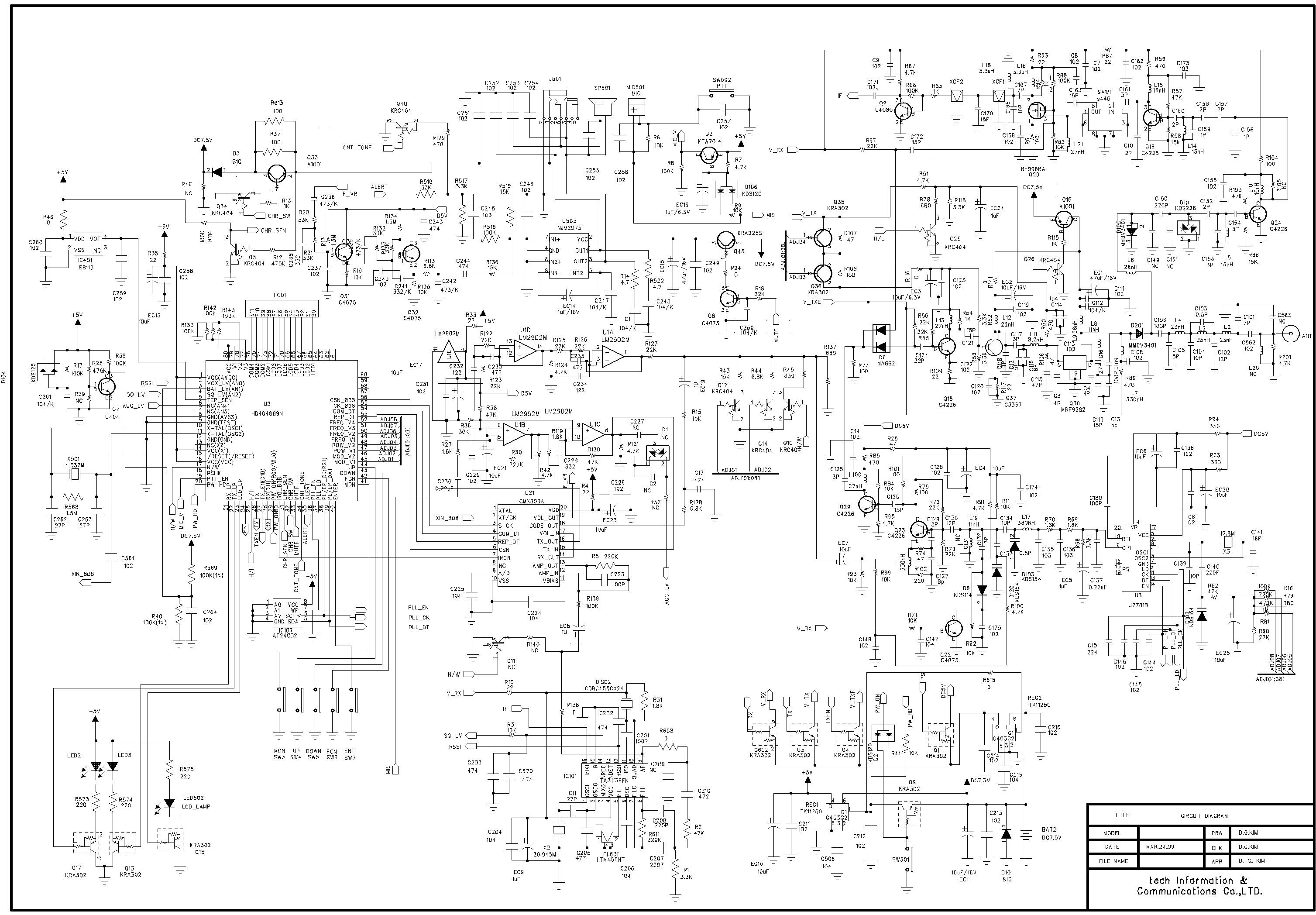
ENGINEERING STATEMENT For Certification of AIRTECH INFORMATION & COMMUNICATION CO., LTD. Model No. ARH-465 FCC ID: ONKARH-465 I am an Electronics Engineer, a principal in the firm of Hyak Laboratories, Inc., Springfield, Virginia. My education and experience are a matter of record with the Federal Communications Commission. Hyak Laboratories, Inc. has been authorized by Airtech Information & Communication Co., Ltd. to make certification measurements on the ARH-465 transceiver. These tests were made by me or under my supervision in our Springfield laboratory. Test data and documentation required by the FCC for certification are included in this report. The data verifies that the above mentioned transceiver meets FCC requirements and certification is requested. _________________________ Rowland S. Johnson Dated: September 21, 2000 A. INTRODUCTION The following data are submitted in connection with this request for type acceptance of the ARH-465 transceiver in accordance with Part 2, Subpart J of the FCC Rules. The ARH-465 is a hand-held, battery operated, UHF, frequency modulated, 2 W (conducted rating) transceiver intended for voice communications applications in the 462.5500 - 462.7250 MHz band under Part 95 in the GMRS service. (ERP (d) was 1.7 W.) B. GENERAL INFORMATION REQUIRED FOR TYPE ACCEPTANCE (Paragraph 2.983 of the Rules) 1. Name of applicant: Airtech Information & Communication Co. 2. Identification of equipment: FCC ID: ONKARH-465 a. The equipment identification label is submitted as a separate exhibit. b. Photographs of the equipment are submitted as separate exhibits. 3. Quantity production is planned. 4. Technical description: a. 16k0F3E emission b. Frequency range: 462.5500-462.7250 MHz. c. Operating power of transmitter is fixed at the factory at 2 watts (conducted). d. Maximum power permitted under FCC Part 95 (interstitial) is 5 watts ERP. The ARH-465 fully complied with that power limitation. d. The dc voltage and dc currents at final amplifier: Collector voltage: 6.9 Vdc Collector current: 0.61 A f. Function of each active semiconductor device: See Appendix 1. g. Complete circuit diagram is submitted as a separate exhibit. h. A draft instruction book is submitted as a separate exhibit. i. The transmitter tune-up procedure is submitted as a separate exhibit. 2 B. GENERAL INFORMATION (continuted) j. A description of circuits for stabilizing frequency is included in Appendix 2. k. A description of circuits and devices employed for suppression of spurious radiation and for limiting modulation is included in Appendix 2. l. Not applicable. 5. Data for 2.985 through 2.997 follow this section. C. RF POWER OUTPUT (Paragraph 2.985(a) of the Rules) RF power output was measured with a Bird 4421 RF power meter and a Narda 765-20 attenuator as a 50 ohm dummy load. Maximum power was 2.0 watts. (The transmitter was tuned by the factory.) For ERP (d) computation see Table 2. D. MODULATION CHARACTERISTICS 1. A curve showing frequency response of the transmitter is shown in Figure 1. Reference level was audio signal output from a Boonton 8220 modulation meter with one kHz deviation. Audio output was measured with an Audio Precision System One TRMS voltmeter and tracking generator. 2. Modulation limiting curves are shown in Figure 2, using a Boonton 8220 modulation meter. Signal level was established with an Audio Precision System One. The curves show compliance with paragraphs 2.987(b) and 95.633(b). 3. Figure 3 is a graph of the post-limiter low pass filter which meets the requirements of paragraph 95.633(b) in providing a roll-off of 60Logf/3 dB where f is audio frequency in kHz. Measurements were made following EIA RS-152B with an Audio Precision System One on the Boonton 8220 modulation meter audio output. 4. Occupied_Bandwidth (Paragraphs 2.989(c), 90.209(b)(4), and 95.629(a) of the Rules) Figure 4 is a plot of the sideband envelope of the transmitter output taken with a Tektronix 494P spectrum analyzer. Modulation corresponded to conditions of 2.989(c)(1) and consisted of a 2500 Hz tone at an input level 16 dB greater than that necessary to produce 50% modulation at 2186 Hz, the frequency of maximum response. Measured modulation at 2186 was 5 kHz. 3 C. MODULATION CHARACTERISTICS (continued) The plot is within the limits imposed by Paragraph 90.211(h) for frequency modulation. The horizontal scale (frequency) is 10 kHz per division and the vertical scale (amplitude) is a logarithmic presentation equal to 10 dB per division. 5. Emission Designator Calculation: (2D + 2F) 2x5.0 + 2x3.0 = 16k0F3E 4 FIGURE 1 MODULATION FREQUENCY RESPONSE MODULATION FREQUENCY RESPONSE FCC ID: ONKARH-465 FIGURE 1 5 FIGURE 2 AUDIO LIMITER CHARACTERISTICS AUDIO LIMITER CHARACTERISTICS FCC ID: ONKARH-465 FIGURE 2 6 FIGURE 3 AUDIO LOW PASS FILTER RESPONSE AUDIO LOW PASS FILTER RESPONSE FCC ID: ONKARH-465 FIGURE 3 7 FIGURE 4 OCCUPIED BANDWIDTH ATTENUATION IN dB BELOW MEAN OUTPUT POWER Required On any frequency more than 50% up to and including 100% of the 25 authorized bandwidth, 20 kHz (10-20 kHz) On any frequency more than 100%, up to and including 250% of the 35 authorized bandwidth (20-50 kHz) On any frequency removed from the assigned frequency by more 43+10LogP = 46 than 250% of the authorized (P = 2.0W) bandwidth (over 50 kHz) OCCUPIED BANDWIDTH FCC ID: ONKARH-465 FIGURE 4 8 E. SPURIOUS EMISSIONS AT THE ANTENNA TERMINALS (Paragraph 2.991 of the Rules) The ARH-465 transmitter was tested for spurious emissions at the antenna terminals while the equipment was modulated with a 2500 Hz signal, 16 dB above minimum input signal for 50% (2.5 kHz deviation) modulation at 2186 Hz, the frequency of highest sensitivity. Measurements were made with Tektronix 494P spectrum analyzer coupled to the transmitter output terminal through Narda 765-20 microwave power attenuator. During the tests, the transmitter was terminated in the 50 ohm attenuator. Power was monitored on a Bird 43 Thru-Line wattmeter; dc supply was 7.5 …
Text truncated - open the document above for the full version.
Contact Information
Applicant
John Kim(Assistant Manager)
Technical Contact
Hyak Laboratories, Inc.Rowland S Johnson
[email protected](703) 451-1188
7011 Calamo St., Suite 107 · Springfield, Virginia · United States
Non-Technical Contact
Hyak Laboratories, Inc.Georgia Hall
[email protected](703) 451-1188
Test Firm
Hyak Laboratories, Inc.Rowland Johnson
703-451-1188
Technical Specifications
| # | Rule Parts | Frequency Range | Power Output | Emission | Tolerance |
|---|---|---|---|---|---|
| 1 | 95A | 462.55 MHz - 462.725 MHz | 1.7 W | 16K0F3E | 0.0005000000 % |
Other Applications from Airtech Information & Communication Co., Ltd.

ONKATS-100
Feb 16, 2004FM HANDHELD TRANSCEIVER
Equipment Class
TNF - Licensed Non-Broadcast Transmitter Held to Face
ONKATP-100
Feb 12, 2004FM Handheld Transceiver
Equipment Class
TNF - Licensed Non-Broadcast Transmitter Held to Face
ONKATP-400B
Nov 03, 2003FM HANDHELD TRANCEIVER
Equipment Class
TNF - Licensed Non-Broadcast Transmitter Held to Face
ONKATS-400B
Nov 03, 2003FM HANDHELD TRANCEIVER
Equipment Class
TNF - Licensed Non-Broadcast Transmitter Held to Face
ONKAT100A
May 30, 2002VHF-FM Handheld Transceiver
Equipment Class
TNF - Licensed Non-Broadcast Transmitter Held to Face