ONKATP-100FM Handheld Transceiver
Airtech Information & Communication Co., Ltd.
Click to zoom
Application Details
- Equipment Class
- TNF - Licensed Non-Broadcast Transmitter Held to Face
- Date of Grant
- Feb 12, 2004
- Application Purpose
- Original Equipment
- Date of Application
- Nov 04, 2003
- Equipment Note
- FM Handheld Transceiver
- Frequency Range
- 136.02500000 - 173.97500000
- Country
- South Korea
Documents & Files
Document Text
Text extracted from the exhibit documents filed with the FCC. Open a document above to read the original.
Users Manual
User’s Manual Land Mobile Radio (LMR) Model: ATP-100 APPROVAL 1. FCC Approval FCC ID: ONKATP-100 1) Safety Training Information Your FM Handheld Transceiver generates RF electromagnetic energy during tran smit mode. This radio is designed for and classified as “Controlled Exposure / Occupation Environment”, meaning it must be used only during the course of employment by individuals aware of the hazards, and the ways to minimize such hazards. This radio is NOT intended for use by the “General Population/Uncontrolled Environment. This radio complies with FCC RF radiation exposure limits set forth for a controlled environment. This radio should be installed and operated with a minimum distance of 2.5 centimeters between the radio and your body. Therefore, to ensure that your exposure to RF electromagnetic energy is within the FCC allowable limits for occupational use, always follow below information. Do not operate the radio wit hout a proper antenna as this may damage the radio and may also cause you to exceed FCC RF exposure limits. A proper antenna is the antenna supplied with this radio by the manufacturer or an antenna specifically authorized by the manufacturer for use with this radio. Do not transmit for more than 50% of total radio use time (“50% duty cycle”). Transmitti ng more than 50% of the time can cause FCC RF exposure compliance requirements to be exceeded. Always use Airtech supplied acce ssories (antennas, batteries, belt clips, speaker/mics, etc.). Use of unauthorized accessories can cause the FCC RF exposure compliance requirements to be exceeded. Always keep the antenna at least 2.5 cm (1 inch) away from the body when transmitting and only use the belt-clips, when attaching the radio to your belt, etc., to ensure FCC RF exposure compliance requirements are not exceeded. 2) LABEL 3) This device complies with the F CC Rules. Operation is subject to the following two conditions: (1) this device may not cause harmful interference, and (2) this device must accept any interference received, includin g interference that may cause undesired operation. CAUTION : Changes or modifications not expressly approved by the party responsible for compliance could void the user’s authority to operate the equipment. This radio complies with the FCC RF exposure limits for OccupationalUse Only. 3 RF Exposure Tests for SAR are conducted using standard operating positions specified by the FCC with the phone transmitting at its highest certified power level in all tested frequency bands. Although the SAR is determined at the highest certified power level, the actual SAR level of the phone while operation can be well below the maximum value. This is because the phone is designed to operate at multiple power levels so as to use only the power required to reach the network. In general, the closer you are to a wireless base station antenna, the lower the power output. Before a phone model is available for sale to the public, it must be tested and certified to the FCC that it does not exceed the limit established by the government-adopted requirement for safe exposure, The tests are performed in positions and location (e.g., at the ear and worn on the body) as required by the FCC for each model. (Body-worn measurements may differ among phone models, depending upon available accessories and FCC requirements). While there may be differences between the SAR levels of various phones and at various positions, they all meet the government requirement for safe exposure. For body worn operation, to maintain compliance with FCC RF exposure guidelines, use only accessories that contain no metallic components and provide a separation distance of 15mm (0.6 inches) to the body. Use of other accessories may violate FCC RF exposure guidelines and should be avoided. It is designed and manufactured not to exceed the emission limits for exposure to radio frequency (RF) energy set by the Federal Communications Commission of the U.S. Government. These limits are part of comprehensive guidelines and establish permitted levels of RF energy for the general population. The guidelines are based on the safety standards previously set by both U.S. and international standards bodies: This EUT has been shown to be capable of compliance for localized specific absorption rate (SAR) for uncontrolled environment/general population exposure limits specified in ANSI/IEE Std. C95.1-1992 and had been tested in accordance with the measurement procedures specified in FCC/OET Bulletin 65 Supplement C (2001) and IEE Std. 1528-200X (Draft6.5, January 2002). Ministry of Health (Canada), Safety Code 6. The standards include a substantial safety margin designed to assure the safety of all persons, regardless of age and health. The exposure standard for wireless mobile phones employs a unit of measurement know as the Specific Absorption Rate, or SAR. The SAR limit set by the FCC is 1.6W/kg*. CONTENTS GENERAL FEATURES.................................................4 UNPACKING.................................................................5 OPTIONAL ACCESSORIES.........................................5 GETTING READY.........................................................2 DESCRIPTION..............................................................3 OPERATION .................................................................4 CHARGER AND BATTERY..........................................5 General Features 1. Ultra compact design & size (102(W)x50(H)x36(D), 310g with high capable battery) 2. Heavy duty durable construction 3. 256 channels 4. 38 CTCSS/ 83 CDCSS/ 83 INVERR CDCSS 5. PC Programmable, transferable by cloning 6. Time-out timer (TOT) 7. Busy Lockout (BCLO) 8. Battery saving mode 9. Low battery alert 10. DTMF ANI 11. Transmit output power High/Low 12. DC 7.5V LI-1700 battery Unpacking Unpack and check that all items have been enclosed. Packing contents: ① radio ② antenna ③ battery pack (1,700 mAH) ④ belt clip ⑤ hand strap ⑥ charger ⑦ user’s m…
Text truncated - open the document above for the full version.
Cover Letter(s)
ELECTRONIC TECHNOLOGY SYSTEMS DR.GENZ GMBH ELECTRONIC TECHNOLOGY SYSTEMS DR. GENZ GMBH - ETS - STORKOWER STRASSE 38c, D-15526 REICHENWALDE B. BERLIN Tel: 033631 888 000 FAX: 033631 888 660 Federal Communications Commission Authorization and Evaluation Division Equipment Authorization Branch 7435 Oakland Mills Road Columbia, MD 21046 IHR ZEICHEN / YOUR REF. IHR SCHREIBEN / YOUR INFORM. UNSER ZEICHEN / OUR REF. DATUM / DATE Nov. 05, 2003 Subject: Application for Certification Applicant: Airtech Information & Communication Co., Ltd. Equipment: FM TRANSCEIVER FCC ID: ONKATP-100 Dear Sirs, Submitted herewith, on behalf of Airtech Information & Communication Co., Ltd., is an application for certification under FCC Rule Part 90 and 90.210 of the following equipment: FM HANDHELD TRANSCEIVER / FCC ID: ONKATP-100 Attached are the Confidentiality request letter, test report (TestRpt1=test data, TestRpt2=test plots), RF Exposure (SAR Measurement Report), FCC ID label and label location information, test setup photographs, internal and external photographs, operational description, part’s list, block diagrams, schematics and user manual. In accordance with 0.459 of CFR 47 Airtech Information & Communication Co., Ltd. hereby requests confidentiality of all Schematics, Parts List (see attached Confidentiality Request Letter) for the subject application. Should you have any questions or comments concerning the above, please contact the following e-mail addresses: [email protected] and [email protected] Thanks a lot. Yours faithfully, Axel Müller ___________________________________________________________________________________ ETS Handelsregister: Bankverbindung: Electronic Technology Systems Dr. Genz GmbH Amtsgericht Frankfurt/Oder HRB 5151 Sparkasse Oder-Spree Storkower Strasse 38c Geschäftsführung: Dr. Dietmar Genz BLZ 170 550 50 D-15526 Reichenwalde b. Berlin Norbert Kaspar Kto. Nr. 3105165974
Cover Letter(s)
Federal Communications Commission Equipment Authorization Branch 7435 Oakland Mills Road Columbia, MD 21046 Request for Confidentiality
External Photos
ELECTRONIC TECHNOLOGY SYSTEMS DR.GENZ GMBH ETS Dr. Genz GmbH, GermanyRegistration number: G5M203060118-C-1Page 1 of 16 Appendix A. Pictures ELECTRONIC TECHNOLOGY SYSTEMS DR.GENZ GMBH ETS Dr. Genz GmbH, GermanyRegistration number: G5M203060118-C-1Page 2 of 16 ELECTRONIC TECHNOLOGY SYSTEMS DR.GENZ GMBH ETS Dr. Genz GmbH, GermanyRegistration number: G5M203060118-C-1Page 3 of 16 ELECTRONIC TECHNOLOGY SYSTEMS DR.GENZ GMBH ETS Dr. Genz GmbH, GermanyRegistration number: G5M203060118-C-1Page 4 of 16 ELECTRONIC TECHNOLOGY SYSTEMS DR.GENZ GMBH ETS Dr. Genz GmbH, GermanyRegistration number: G5M203060118-C-1Page 5 of 16
ID Label/Location Info
Airtech I & C Co.,Ltd. 421-809, #101-807, Techno ParkComplex, 364,Samjung-dong, Ojung-Gu,Bucheon-si,Kyeonggi-do,Korea Tel : +82-32-234-2345 / Fax :+82-32-234-2350 Home : www. Airtech21.com /e-mail : [email protected] [Label Location] Description : VHF FM TRANSCEIVER FCC ID:ONKATP-100
ID Label/Location Info
FCC ID: ONKATP-100 AIRTECH VHF FM TRANSCEIVER FCC ID: ONKATP-100 RF POWER RATING 4W S/NO.: AIRTECH I&C Co.,Ltd. Made in Korea THIS DEVICE COMPLIES WITH PART 90 OF THE FCC RULES. OPERATION IS SUBJECT TO THE CONDITION THAT THIS DEVICE MAY NOT CAUSE HARMFUL INTERFERENCE. . Restricted to occupational use to satisfy FCC RF exposure limits. See user manual fo r operating requirements
Internal Photos
ELECTRONIC TECHNOLOGY SYSTEMS DR.GENZ GMBH ETS Dr. Genz GmbH, GermanyRegistration number: G5M203060118-C-1Page 6 of 16 ELECTRONIC TECHNOLOGY SYSTEMS DR.GENZ GMBH ETS Dr. Genz GmbH, GermanyRegistration number: G5M203060118-C-1Page 7 of 16 ELECTRONIC TECHNOLOGY SYSTEMS DR.GENZ GMBH ETS Dr. Genz GmbH, GermanyRegistration number: G5M203060118-C-1Page 8 of 16 ELECTRONIC TECHNOLOGY SYSTEMS DR.GENZ GMBH ETS Dr. Genz GmbH, GermanyRegistration number: G5M203060118-C-1Page 9 of 16 ELECTRONIC TECHNOLOGY SYSTEMS DR.GENZ GMBH ETS Dr. Genz GmbH, GermanyRegistration number: G5M203060118-C-1Page 10 of 16 ELECTRONIC TECHNOLOGY SYSTEMS DR.GENZ GMBH ETS Dr. Genz GmbH, GermanyRegistration number: G5M203060118-C-1Page 11 of 16
Operational Description
[OPERATIONAL DESCRIPTION] Description : VHF FM TRANSCEIVER FCC ID:ONKATP-100 INTRODUCTION ATP-100 is a micro size 90 channel portable FM transceiver constructed with a microprocessor controlled, temperature compensated Phase Locked Loop (PLL) frequency synthesizer. The radio features a double conversion receiver and a direct FM transmitter modulator. A special integrated circuit provides support to sub- audible signaling (CTCSS & DCS) and most of the receiving parts are switched off periodically in the power saver mode to reduce battery current drain during standby. The Block Diagram RF and Control Circuit Diagrams for ATP-100 shall be used in associate with the following circuit description. CIRCUIT DESCRIPTIONS 1) PHASE-LOCK LOOP (PLL) CIRCUIT * REFERENCE OSCILLATOR The reference oscillator consists of TCX301 in U301 with a frequency of 12.8MHz. The reference oscillator frequency is stabilized by the thermistor TH301 and drives a divider to produce a comparison frequency. This comparison frequency is selected by decoding the first three bits of the data input from microcomputer. * PROGRAMMABLE DIVIDER The programmable divider in U301 consists of a two-modulus prescaler with a 7bit control register followed by a 11-bit internal programmable divider. The overall division ratio is selected by a single 19-bit world located on the serial data bus. * PHASE COMPARATOR A digital-type phase comparator in U301 with output(pin 15, 16) and an open drain lock detect output(pin 7) compares divided VCO frequency with the comparison frequency. It generates a correction voltage that is applied to a low-pass filter consisting of R307, R310, R311 and C312, C313, C314 then sent to the VCO circuit. * VCO CIRCUIT The transmit/receive frequency is directly generated by the Colpitts oscillation circuit contains Q401, Q405. The oscillation frequency is variable by applying the VCO control voltage to variable to variable capacitors D401, D408 and D403,404,405. To switch between the transmit and receive frequencies, Q402 turn on, and Q401 (VCO for transmission) oscillates when the T/R pin is low. 2) TRANSMITTER * MIC AMP CIRCUIT Voice signal from the microphone are applied to microphone amplifier U601 through CON 601 . U601 contains a low-pass filter that has a 6dB/oct response between 300Hz and 3 kHz,and eliminates hamonics above 3 kHz. The pre-emphasized audio signal is applied to VR303 from U606 pin 22 to adjust maximum frequency deviation. * VCO AND AMPLIFIER The VCO signal output is amplified by Q203 and then fed to power module Q204. * POWER AMPLIFIER CIRCUIT Q204 is provided approximately 7.5V DC power source. RF power output is adjusted by variable resistors VR501 (High Power) and VR502 (Low Power). Signals from Q204 is supplied through antenna switch D201 to a low-pass filter made up of L207, L208, L211 and C101-C104, then applied to Antenna Jack. 3) RECEIVER * ANT SWITCHING CIRCUIT Signals from antenna connector fed to the antenna switching circuit throught the low pass filter consisting of L207,.L208,L211 and C235-C238,C241~C243. In receive mode, D201 is turned off, isolates the antenna from the transmitter circuit and matching circuitry, so that the incoming signals are fed to the RF amplifier through L101. * RF AMPIFIER CIRCUIT The signals from the switching circuit are fed to the RF amplifier Q101 through a band pass filter made up of mold coil , vvc diode and capacitor. * FIRST MIXER CIRCUIT The amplified signals are fed to Gate 1 of the first mixer Q102 through C123. First local oscillator signal is supplied to Gate 2 of Q102 form the PLL circuit through C129 to convert the RF signals into 21.4MHz first IF signal. * IF CIRCUIT The first IF signals from Q102 are fed to the matched pair crystal filter FL101, then IF signals are amplified in Q103. And those signals are fed to U101 which is composed of the second local oscillator, second mixer, limiter amplifier, quadrature detector and active filter circuit. The second local oscillator at 20.945MHz with X101and is fed to the second mixer with the first IF signals to convert into 455kHz second IF signals.. The second IF signals leave through pin 3,and are fed to external ceramic filters FL102,FL122 which has excellent selectivity, then fed to U101 (pin 5) again to be amplified and detected. Narrow /Wide band are switched by diode D107,D108,Q105,Q106 The detected AF signals are output from pin 9. * AUDIO AND SQUELCH CIRCUIT The detected audio signals are put through a 6dB/oct de-emphasis circuit made up of C699 and R690. The signal is then applied to audio power amplifier U607 through the volume control SVR601 to obtain enough power to driver the speaker.
Operational Description
[ANTENNA SPECIFICATION] Description : VHF FM TRANSCEIVER FCC ID:ONKATP-100
RF Exposure Info
ELECTRONIC TECHNOLOGY SYSTEMS DR. GENZ GMBH TEST - REPORT SAR Compliance Test Report Test report no.: G5M203060118-S-8 SAR ELECTRONIC TECHNOLOGY SYSTEMSSTORKOWER STRASSE 38C, D-15526 REICHENWALDE B. BERLIN DR. GENZ GMBHPHONE +49-33631-888 00 FAX +49-33631-888 660 ETS Dr. Genz GmbH, GermanyRegistration number: G5M203060118-S-8Page 1 of 20 ELECTRONIC TECHNOLOGY SYSTEMS DR.GENZ GMBH TABLE OF CONTENTS 1General information 1.1Notes 1.2Testing laboratory 1.3Details of approval holder 1.4 Manufacturer 1.5Application details 1.6Test item 1.7Test results 1.8Test standards 2Technical test 2.1Summary of test results 2.2Test environment 2.3Test equipment utilized 2.4Definitions 2.5Measurement system description 2.6Test system specification 2.7Measurement procedure 2.8Reference positions for handheld radio transmitters 2.9Measurement uncertainty 3Tissue and system verification 3.1Tissue verification 3.2System verification 4Test Results 5References 6Appendix ETS Dr. Genz GmbH, GermanyRegistration number: G5M203060118-S-8Page 2 of 20 ELECTRONIC TECHNOLOGY SYSTEMS DR.GENZ GMBH 1General Information 1.1Notes The purpose of conformity testing is to increase the probability of adherence to the essential requirements or conformity specifications, as appropriate. The complexity of the technical specifications, however, means that full and thorough testing is impractical for both technical and economic reasons. Furthermore, there is no guarantee that a test sample which has passed all the relevant tests conforms to a specification. The existence of the tests nevertheless provides the confidence that the test sample possesses the qualities as maintained and that is performance generally conforms to representative cases of communications equipment. The test results of this test report relate exclusively to the item tested as specified in 1.5. The test report may only be reproduced or published in full. Reproduction or publication of extracts from the report requires the prior written approval of the ELECTRONIC TECHNOLOGY SYSTEMS DR. GENZ GMBH. I attest to the accuracy of data. All measurements reported herein were performed by me or were made under my supervision and are correct to the best of my knowledge and belief. I assume full responsibility for the completeness of these measurements and vouch for the qualification of all persons taking them. Tester: 23.10.2003N. Kaspar DateETS-Lab.NameSignature Technical responsibility for area of testing: 23.10.2003Dr. Genz DateETSNameSignature ETS Dr. Genz GmbH, GermanyRegistration number: G5M203060118-S-8Page 3 of 20 ELECTRONIC TECHNOLOGY SYSTEMS DR.GENZ GMBH 1.2 Testing laboratory 1.2.1Location ELECTRONIC TECHNOLOGY SYSTEM DR. GENZ GMBH (ETS) Storkower Straße 38c D-15526 Reichenwalde b. Berlin Germany Telephone : +49 33631 888 00 Fax: +49 33631 888 660 1.2.2Details of accreditation status ACCREDITED TESTING LABORATORY DAR-REGISTRATION NUMBER: TTI-P-G 126/96 FCC FILED TEST LABORATORY REG. NO. 96970 BLUETOOTH QUALIFICATION TEST FACILITY (BQTF) ACCREDITED BY BLUETOOTH QUALIFICATION REVIEW BOARD INDUSTRY CANADA FILED TEST LABORATORY REG. NO. IC 3470 A2LA ACCREDITED Certificate Number 1983-01 1.3Details of approval holder Name: Airtech I & C Co., Ltd. Street: zip 421-809, #101-807, Techno ParkComplex, 364, Samjung- dong Town: Ojung-Gu, Bucheon-si, Kyeonggi-Do Country: Korea Telephone: +82-32-234-2345 Fax: +82-32-234-2350 Contact: Mr. John Kim E-Mail: [email protected] 1.4Manufacturer: (if applicable) Name: Street: Town: Country: ETS Dr. Genz GmbH, GermanyRegistration number: G5M203060118-S-8Page 4 of 20 ELECTRONIC TECHNOLOGY SYSTEMS DR.GENZ GMBH 1.5Application details Date of receipt of application: 23.06.2003 Date of receipt of test item: 23.06.2003 Date of test: 26.09.2003 1.6Test item FCC ID: ONKATP-100 Description of test item: VHF Transceiver Type identification: ATP-100 Serial number: without;Identical prototype Device category: PCF (Licensed Portable Transmitter Held To Face) Technical data TX Frequency range: 136.025 - 173.975 MHz RX Frequency range: 136.025 - 173.975 MHz Max. Conducted RF output power : 36,95 dBm (4,955 W) Power supply : 7,5 V DC Antenna Tx: external Antenna RX: external Antenna type: Helical Antenna Additional information: Tx and Rx. antenna are the same. 1.7Test Results Max. SAR Measurement: 1.90 W/kg (averaged over 1 gram) This EUT has been shown to be capable of compliance for localized specific absorption rate (SAR) for uncontrolled environment/general population exposure limits specified in ANSI/IEEE Std. C95.1-1992 and had been tested in accordance with the measurement procedures specified in FCC/OET Bulletin 65 Supplement C (2001) and IEEE Std. 1528-200X (Draft 6.5, January 2002). ETS Dr. Genz GmbH, GermanyRegistration number: G5M203060118-S-8Page 5 of 20 ELECTRONIC TECHNOLOGY SYSTEMS DR.GENZ GMBH 1.8Test standards Standards: - IEEE Std. 1528-200X (Draft 6.5, January 2002) FCC Rule Part(s): - FCC OET Bulletin 65, Supplement C, Edition 01-01 2Technical test 2.1Summary of test results Classification Uncontrolled environment/general population Controlled exposure/occupational environmentX Applicable Configuration Handset (Head) Handset (Held to face)X Handset (Body) Headset (Head) Body Worn EquipmentX EUT complies with the RF radiation exposure limits of the FCC as shown by the SAR measurement results. These measurements are taken to simulate the RF effects exposure under worst-case conditions. The EUT complies with the requirements in respect to all parameters subject to the test. The test results and statements relate only to the item(s) tested. Please note that the absorption and distribution of electromagnetic energy in the body are very complex phenomena that depend on the mass, shape, and size of the body, the orientation of the body with respect to the field vectors, and the electrical properties of both the body and the environment. Other variables that may play a substantial role in possible biological effects are those that charac…
Text truncated - open the document above for the full version.
RF Exposure Info
ELECTRONIC TECHNOLOGY SYSTEMS DR. GENZ GMBH TEST - REPORT SAR Compliance Test Report Test report no.: G5M203060118-S-2 SAR ELECTRONIC TECHNOLOGY SYSTEMSSTORKOWER STRASSE 38C, D-15526 REICHENWALDE B. BERLIN DR. GENZ GMBHPHONE +49-33631-888 00 FAX +49-33631-888 660 ETS Dr. Genz GmbH, GermanyRegistration number: G5M203060118-S-2Page 1 of 20 ELECTRONIC TECHNOLOGY SYSTEMS DR.GENZ GMBH TABLE OF CONTENTS 1General information 1.1Notes 1.2Testing laboratory 1.3Details of approval holder 1.4 Manufacturer 1.5Application details 1.6Test item 1.7Test results 1.8Test standards 2Technical test 2.1Summary of test results 2.2Test environment 2.3Test equipment utilized 2.4Definitions 2.5Measurement system description 2.6Test system specification 2.7Measurement procedure 2.8Reference positions for handheld radio transmitters 2.9Measurement uncertainty 3Tissue and system verification 3.1Tissue verification 3.2System verification 4Test Results 5References 6Appendix ETS Dr. Genz GmbH, GermanyRegistration number: G5M203060118-S-2Page 2 of 20 ELECTRONIC TECHNOLOGY SYSTEMS DR.GENZ GMBH 1General Information 1.1Notes The purpose of conformity testing is to increase the probability of adherence to the essential requirements or conformity specifications, as appropriate. The complexity of the technical specifications, however, means that full and thorough testing is impractical for both technical and economic reasons. Furthermore, there is no guarantee that a test sample which has passed all the relevant tests conforms to a specification. The existence of the tests nevertheless provides the confidence that the test sample possesses the qualities as maintained and that is performance generally conforms to representative cases of communications equipment. The test results of this test report relate exclusively to the item tested as specified in 1.5. The test report may only be reproduced or published in full. Reproduction or publication of extracts from the report requires the prior written approval of the ELECTRONIC TECHNOLOGY SYSTEMS DR. GENZ GMBH. I attest to the accuracy of data. All measurements reported herein were performed by me or were made under my supervision and are correct to the best of my knowledge and belief. I assume full responsibility for the completeness of these measurements and vouch for the qualification of all persons taking them. Tester: 30.01.2004N. Kaspar DateETS-Lab.NameSignature Technical responsibility for area of testing: 30.01.2004Dr. Genz DateETSNameSignature ETS Dr. Genz GmbH, GermanyRegistration number: G5M203060118-S-2Page 3 of 20 ELECTRONIC TECHNOLOGY SYSTEMS DR.GENZ GMBH 1.2 Testing laboratory 1.2.1Location ELECTRONIC TECHNOLOGY SYSTEM DR. GENZ GMBH (ETS) Storkower Straße 38c D-15526 Reichenwalde b. Berlin Germany Telephone : +49 33631 888 00 Fax: +49 33631 888 660 1.2.2Details of accreditation status ACCREDITED TESTING LABORATORY DAR-REGISTRATION NUMBER: TTI-P-G 126/96 FCC FILED TEST LABORATORY REG. NO. 96970 BLUETOOTH QUALIFICATION TEST FACILITY (BQTF) ACCREDITED BY BLUETOOTH QUALIFICATION REVIEW BOARD INDUSTRY CANADA FILED TEST LABORATORY REG. NO. IC 3470 A2LA ACCREDITED Certificate Number 1983-01 1.3Details of approval holder Name: Airtech I & C Co., Ltd. Street: zip 421-809, #101-807, Techno ParkComplex, 364, Samjung- dong Town: Ojung-Gu, Bucheon-si, Kyeonggi-Do Country: Korea Telephone: +82-32-234-2345 Fax: +82-32-234-2350 Contact: Mr. John Kim E-Mail: [email protected] 1.4Manufacturer: (if applicable) Name: Street: Town: Country: ETS Dr. Genz GmbH, GermanyRegistration number: G5M203060118-S-2Page 4 of 20 ELECTRONIC TECHNOLOGY SYSTEMS DR.GENZ GMBH 1.5Application details Date of receipt of application: 23.06.2003 Date of receipt of test item: 23.06.2003 Date of test: 21.01.2004 - 22.01.2004 1.6Test item FCC ID: ONKATP-100 Description of test item: VHF Transceiver Type identification: ATP-100 Serial number: without;Identical prototype Device category: PCF (Licensed Portable Transmitter Held To Face) Technical data TX Frequency range: 136.025 - 173.975 MHz RX Frequency range: 136.025 - 173.975 MHz Max. Conducted RF output power : 36,95 dBm ( 4.955 W) Power supply : 7,5 V DC rechargeable battery Antenna Tx: external Antenna RX: external Antenna type:Helical Antenna Additional information: Tx and Rx. antenna are the same. 1.7Test Results Max. SAR Measurement: 0,99 W/kg (averaged over 1 gram) This EUT has been shown to be capable of compliance for localized specific absorption rate (SAR) for uncontrolled environment/general population exposure limits specified in ANSI/IEEE Std. C95.1-1992 and had been tested in accordance with the measurement procedures specified in FCC/OET Bulletin 65 Supplement C (2001) and IEEE Std. 1528-200X (Draft 6.5, January 2002). ETS Dr. Genz GmbH, GermanyRegistration number: G5M203060118-S-2Page 5 of 20 ELECTRONIC TECHNOLOGY SYSTEMS DR.GENZ GMBH 1.8Test standards Standards: - IEEE Std. 1528-200X (Draft 6.5, January 2002) FCC Rule Part(s): - FCC OET Bulletin 65, Supplement C, Edition 01-01 2Technical test 2.1 Summary of test results Classification Uncontrolled environment/general population Controlled exposure/occupational environmentX Applicable Configuration Handset (Head) Handset (Held to face)X Handset (Body) Headset (Head) Body Worn EquipmentX EUT complies with the RF radiation exposure limits of the FCC as shown by the SAR measurement results. These measurements are taken to simulate the RF effects exposure under worst-case conditions. The EUT complies with the requirements in respect to all parameters subject to the test. The test results and statements relate only to the item(s) tested. Please note that the absorption and distribution of electromagnetic energy in the body are very complex phenomena that depend on the mass, shape, and size of the body, the orientation of the body with respect to the field vectors, and the electrical properties of both the body and the environment. Other variables that may play a substantial role in possible biolo…
Text truncated - open the document above for the full version.
Test Report
ELECTRONIC TECHNOLOGY SYSTEMS DR. GENZ GMBH TEST - REPORT FCC RULES PART 90 FCC ID: ONKATP-100 Test report no.: G5M203060118-C-1 FCC ELECTRONIC TECHNOLOGY SYSTEMSSTORKOWER STRASSE 38C, D-15526 REICHENWALDE B. BERLIN DR. GENZ GMBHPHONE +49-33631-888 00 FAX +49-33631-888 66 ETS Dr. Genz GmbH, GermanyRegistration number: G5M203060118-C-1Page 1 of 30 ELECTRONIC TECHNOLOGY SYSTEMS DR.GENZ GMBH TABLE OF CONTENTS 1General information 1.1Notes 1.2Testing laboratory 1.3Details of approval holder 1.4Application details 1.5Test item 1.6Test standards 2Technical test 2.1Summary of test results 2.2Test environment 2.3Test equipment utilized 2.4 Test Procedures 2.4.1 Output power conducted 2.4.2 Output power radiated 2.4.3 Spurious Emissions radiated 2.4.4 Spurious Emissions at antenna terminal 2.4.5 Audio frequency response 2.4.6 Audio low pass filter frequency response 2.4.7 Modulation limited 2.4.8 Occupied Bandwidth 2.4.9 Frequency stability 2.4.10 Transient frequency behaviour of the transmitter 2.4.11 Spurious Emissions related to AC power line 3 Test Results 3.1 RF Power Output (conducted) FCC 2.1046(a), FCC 90.205 3.2 Radiated Power FCC 2.1046 3.3 Spurious Emission radiated, FCC 2.1053, FCC 90.210 3.4 Spurious emissions at antenna terminal FCC 2.1051, FCC 90.210(b) (d) 3.5 Audio frequency response FCC 2.1047(a) 3.6 Audio low pass filter frequency response FCC 2.1047(a), FCC 90.210 3.7 Modulation Limiting FCC 2.1047(b), FCC 22.915(b), FCC 90.242(b)(8) 3.8 Occupied Bandwidth FCC 2.1049, FCC 90.210 3.9 Frequency Stability vs. Temperature, FCC 90.213, FCC 2.1055, FCC 22.915(b) 3.10 Transient frequency behaviour of the transmitter FCC 90.214 3.11 Spurious emissions related to AC power line ETS Dr. Genz GmbH, GermanyRegistration number: G5M203060118-C-1Page 2 of 30 ELECTRONIC TECHNOLOGY SYSTEMS DR.GENZ GMBH 1General Information 1.1Notes The purpose of conformity testing is to increase the probability of adherence to the essential requirements or conformity specifications, as appropriate. The complexity of the technical specifications, however, means that full and thorough testing is impractical for both technical and economic reasons. Furthermore, there is no guarantee that a test sample which has Passed all the relevant tests conforms to a specification. Neither is there any guarantee that such a test sample will interwork with other genuinely open systems. The existence of the tests nevertheless provides the confidence that the test sample possesses the qualities as maintained and that is performance generally conforms to representative cases of communications equipment. The test results of this test report relate exclusively to the item tested as specified in 1.5. The test report may only be reproduced or published in full. Reproduction or publication of extractes from the report requires the prior written approval of the ELECTRONIC TECHNOLOGY SYSTEMS DR. GENZ GMBH. Tester: 23.10.2003D. Hoppe DateETS-Lab.NameSignature Technical responsibility for area of testing: 23.10.2003Dr. Genz DateETSNameSignature ETS Dr. Genz GmbH, GermanyRegistration number: G5M203060118-C-1Page 3 of 30 ELECTRONIC TECHNOLOGY SYSTEMS DR.GENZ GMBH 1.2 Testing laboratory 1.2.…
Text truncated - open the document above for the full version.
Contact Information
Applicant
John Kim(Assistant Manager)
Technical Contact
Airtech Information & Communication Co., Ltd.John Kim
[email protected]+82-32-234-2345
#101-807, Techno Park Complex 364 · Buchon-Si, Kyungki-Do · South Korea
Test Firm
Eurofins Product Service GmbHRobert Kschiwan-Kaspar
Technical Specifications
| # | Rule Parts | Frequency Range | Power Output | Emission | Tolerance |
|---|---|---|---|---|---|
| 2 | 9 | 136.025 MHz - 173.975 MHz | 4.955 W | 16K0F3E | 5 ppm |
Other Applications from Airtech Information & Communication Co., Ltd.

ONKATS-100
Feb 16, 2004FM HANDHELD TRANSCEIVER
Equipment Class
TNF - Licensed Non-Broadcast Transmitter Held to Face
ONKATP-400B
Nov 03, 2003FM HANDHELD TRANCEIVER
Equipment Class
TNF - Licensed Non-Broadcast Transmitter Held to Face
ONKATS-400B
Nov 03, 2003FM HANDHELD TRANCEIVER
Equipment Class
TNF - Licensed Non-Broadcast Transmitter Held to Face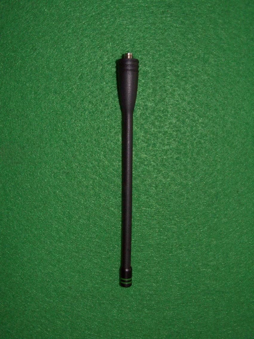
ONKAT100A
May 30, 2002VHF-FM Handheld Transceiver
Equipment Class
TNF - Licensed Non-Broadcast Transmitter Held to Face
ONKAT-400B
Oct 21, 2001UHF FM TRANSCEIVER
Equipment Class
TNF - Licensed Non-Broadcast Transmitter Held to Face