OOALK3A-2LK3A-2 Link Unit
Maynetronics Ltd
Click to zoom
Application Details
- Equipment Class
- DXT - Part 15 Low Power Transceiver, Rx Verified
- Date of Grant
- Oct 05, 1999
- Application Purpose
- Original Equipment
- Date of Application
- Aug 12, 1999
- Equipment Note
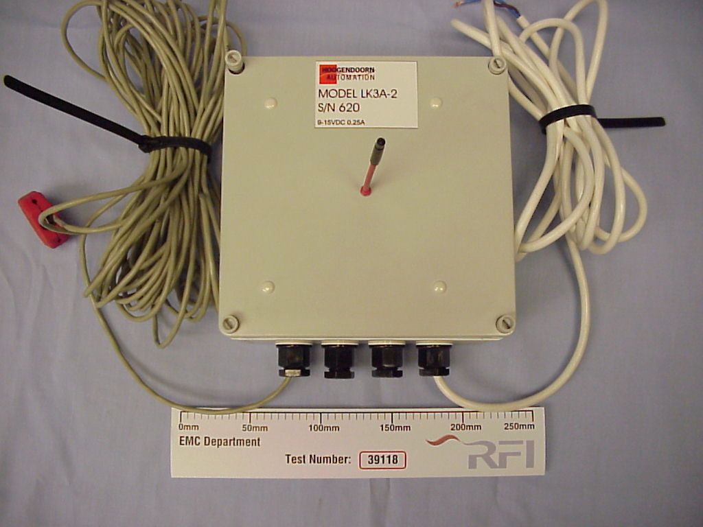
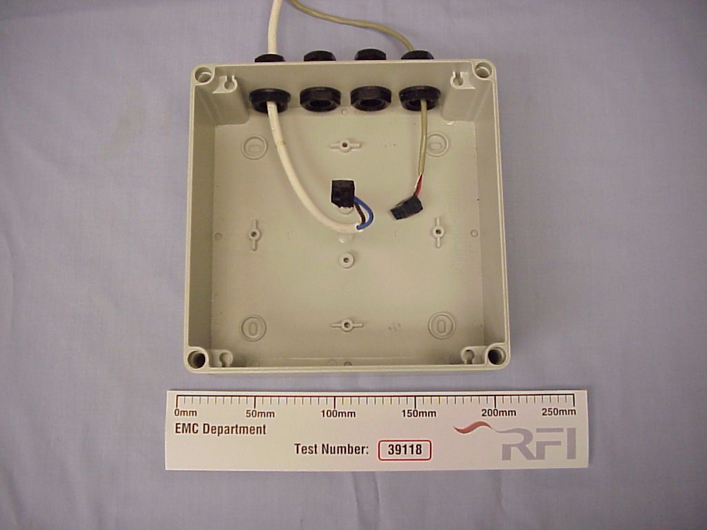
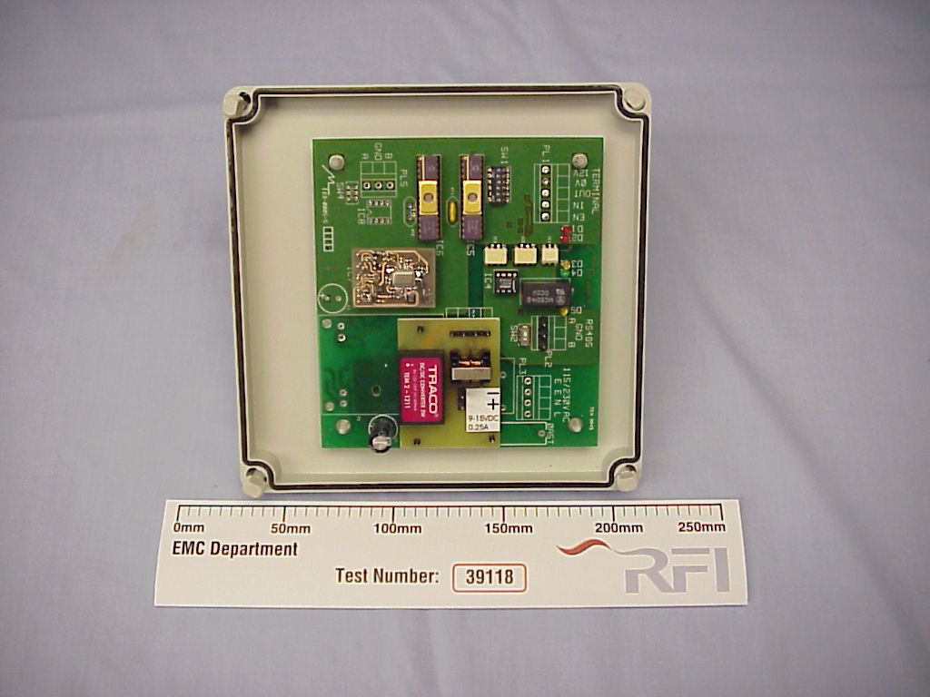
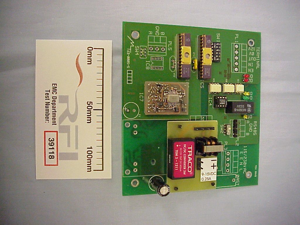
- LK3A-2 Link Unit
- Frequency Range
- 916.50000000 - 916.50000000
- Company
- Maynetronics Ltd
- Country
- United Kingdom
Documents & Files
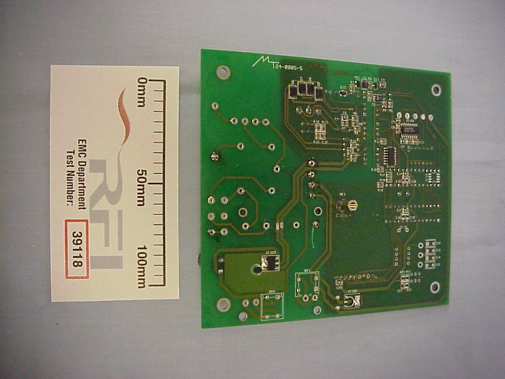
Document Text
Text extracted from the exhibit documents filed with the FCC. Open a document above to read the original.
Users Manual
OPERATION MANUAL FOR LK3A-2 LINK UNIT NOMADLK3A-2 Tested To Comply With FCC Standards FOR HOME OR OFFICE USE NOMAD™ - LK3A-2 O PERATING INSTRUCTIONS PAGE 3 of 9 1.INTRODUCTION..................................................................................................................4 2.SPECIFICATION .................................................................................................................4 2.1 CERTIFICATION .............................................................................................................................. 4 2.2 CABLE LENGTHS ............................................................................................................................ 4 2.2.112V DC POWER CABLING ..................................................................................................... 4 2.2.2Network Cabling ....................................................................................................................... 5 3.INSTALLATION ...................................................................................................................6 3.1 MOUNTING.......................................................................................................................................... 6 3.2 C ONNECTIONS.................................................................................................................................... 6 3.3 N ETWORK IDENTIFIER.......................................................................................................................... 7 3.4 A NTENNA............................................................................................................................................ 8 4.MAINTAINENCE..................................................................................................................8 NOMAD™ - LK3A-2 O PERATING INSTRUCTIONS PAGE 4 of 9 1. INTRODUCTION The LK3A-2 link unit is a remote transceiver for the NOMAD system. Its purpose is to provide the radio link to wireless NOMAD terminals. Several of these link units can be connected to the same controller via a single twisted pair cable. Each link unit is powered from a 12V DC supply. 2. SPECIFICATION Power10-18V DC Average Consumption100mA Radio link Frequency916.5MHz 2.1 CERTIFICATION This device complies with part 15 of the FCC rules. Operation is subject to the following two conditions: (1) this device may not cause harmful interference, and (2) this device must accept any interference received, including interference that may cause undesired operation. 2.2 CABLE LENGTHS 2.2.1 12V DC POWER CABLING When fitting the link unit ensure that the voltage at the link unit is in the range 10 to 18 V DC. Voltage drop between the power supply and the link units will depend on the cable used and the number of link units connected to a single power supply. The following table gives maximum cable lengths for some common configurations. Note that the cable length is from the power supply to the farthest link unit for a single cable run. It would be normal practice to make two or more cable runs from a single power supply (in different directions). NOMAD™ - LK3A-2 O PERATING INSTRUCTIONS PAGE 5 of 9 12V DC supply: # Of Link Units1.0mm 2 1.5mm 2 1171256 2133199 3108163 492138 15V DC supply: # Of Link Units1.0mm 2 1.5mm 2 1427641 2332499 3272408 4230345 2.2.2 Network Cabling The maximum cable length for the network cable is dictates the distance from the controller to the farthest link unit. This is typically 1km. Note that if the controller is centrallly placed this gives a maximum distance from one end to the other of 2km. NOMAD™ - LK3A-2 O PERATING INSTRUCTIONS PAGE 6 of 9 3. INSTALLATION The LK3A-2 has been designed to be permanently installed 3.1 MOUNTING Whilst the general location for each link unit will be dictated from a system viewpoint individual link units should adhere to the following guidelines 1. Avoid mounting adjacent to metal pillars etc. 2. The antenna should have a vertical orientation. It is usual to mount the link unit suspended over a main path with the antenna pointing vertically downwards. A fixing kit is supplied that assists in attaching the link unit to parallel overhead support wires, see figure 1 at the end of this manual. 3.2 CONNECTIONS The network connection should be made using screened twisted pair cable with a characteristic impedance of 110Ω. When connecting multiple link units to a single controller each item of equipment (link unit or controller) should be daisy chained - the cable starts at one item and then goes to the next, and then the next and so on. Do not use a star configuration - one item has connections running from it to more than two other items. The last two items, and only the last two items, in the chain should have their terminators switched on. For the link units this is achieved by sliding switch SW2 to the left - see above. NOMAD™ - LK3A-2 O PERATING INSTRUCTIONS PAGE 7 of 9 Take care on 12V DC powered units to observe the correct polarity. Cables connected to the link unit should be fixed so that any moisture running down the cable does not is directed away from the link unit. All glands must be tightened - any unused glands should be fitted with a blanking plug. 3.3 NETWORK IDENTIFIER To enable a link unit to be identified from other link units on the network a unique number is assigned to it using switch SW1 Set the switch as follows (0 is down, 1 is up) IdentifierSettingIdentifierSetting 000000016010000 100000117010001 200001018010010 300001119010011 400010020010100 500010121010101 600011022010110 700011123010111 800100024011000 900100125011001 1000101026011010 1100101127011011 1200110028011100 1300110129011101 1400111030011110 15001111 NOMAD™ - LK3A-2 O PERATING INSTRUCTIONS PAGE 8 of 9 Note that switch SW1 position 6 (leftmost) is reserved for factory test mode and should be in the 0 (down) position for normal use. 3.4 ANTENNA Screw the antenna direct…
Text truncated - open the document above for the full version.
ID Label/Location Info
NOMAD MODEL LK3A-2 S/ N x x x AUTOMATION
Operational Description
TECHNICAL DECRIPTION FOR NOMAD LK3A-2 TERMINAL The NOMAD system comprises a PC, a controller, multiple link units and terminals. The controller connects to the PC via a RS232 link. A RS485 bus connects the controller to the link units. Each terminal has a low powered UHF transceiver that communicates with a similar transceiver in the link units. The number of link units depends on the size of the site. The aim of the whole system is to get data from the terminals onto the PC. The LK3A-2 link unit is a 12V DC powered transceiver with a RS485 interface. Data for transmission is sent to the link unit via the RS485 and received data is sent back down the RS485. The controller schedules all communication over the RS485 interface. Two small, embedded processors with a 4MHz clock provide all the peripheral and control features. On-chip UARTs interface to the wireless and RS485 sections and the two processors communicate via an I 2 C link. The data lines from the RS485 interface are optically isolated from the processor. A DIP switch sets the link unit address. Power supply input is 10-18V DC with a switch mode isolator regulator for the control side and a linear regulator for the RS485 interface. Average consumption is 100mA. The wireless section is centered around a TR1000 hybrid transceiver from Radio Monolithics. This device contains all the necessary RF circuitry with just a few passive components, a 3.3V regulator, and a couple of transistors to perform level shifting of the logic signals. The antenna is a ¼ wave whip connected by a non-standard connector. Operating frequency is 916.5 MHz and the modulation type is OOK.
Test Report
Radio Frequency Investigation Ltd, Ewhurst Park, Ramsdell, Basingstoke, Hampshire, RG26 5RQ, ENGLAND. Tel: +44 (0) 1256 851193 Fax: +44 (0) 1256 851192 Registered in England, No. 211 7901. Registered Office: Ewhurst Park, Ramsdell, Basingstoke, Hampshire RG26 5RQ TESTING 0644 TEST REPORT FROM RADIO FREQUENCY INVESTIGATION LTD. Test Of: Maynetronics Ltd. LK3A-2 Link Box To: FCC Part 15 Subpart C: 1998 (Intentional Radiators) Section 15.249 Test Report Serial No: RFI/EMCB1/RP39118ETF02B This Test Report Is Issued Under The Authority Of Brian Watson Technical Director: Checked By: Tested By: pp Release Version No: PDF01 Issue Date: 22 July 1999Test Date: 21 June 1999, 24 June 1999 and 8 July 1999 This report is issued in Adobe Acrobat portable document format (PDF). It is only a valid copy of the report if it is being viewed in PDF format with the following security options not allowed: Changing the document, Selecting text and graphics, Adding or changing notes and form fields. Furthermore, the date of creation must match the issue date stated above. This report may be copied in full. RADIO FREQUENCY INVESTIGATION LTD.Test Report S.No. RFI/EMCB1/RP39118ETF02B EMC DepartmentPage 2 of 34 Issue Date: 22 July 1999 Test Of:Maynetronics Ltd. LK3A-2 Link Box To:FCC Part 15 Subpart C: 1998 (Intentional Radiators) Section 15.249 This page has been left intentionally blank. RADIO FREQUENCY INVESTIGATION LTD.Test Report S.No. RFI/EMCB1/RP39118ETF02B EMC DepartmentPage 3 of 34 Issue Date: 22 July 1999 Test Of:Maynetronics Ltd. LK3A-2 Link Box To:FCC Part 15 Subpart C: 1998 (Intentional Radiators) Section 15.249 Table of Contents 1. Client Information..........................................................................................................4 2. Equipment Under Test (EUT)........................................................................................5 3. Test Specification, Methods & Procedures..................................................................7 4. Deviations From The Test Specification......................................................................8 5. Operation Of The EUT During Testing..........................................................................9 6. Summary Of Test Results...........................................................................................10 7. Measurements, Examinations And Derived Results.................................................11 8. Measurement Uncertainty...........................................................................................19 Appendix 1. Test Equipment Used..................................................................................20 Appendix 2. Measurement Methods................................................................................21 Appendix 3. Test Configuration Drawings......................................................................26 Appendix 4. Graphical Test Results................................................................................30 Appendix 5. Photographs of EUT....................................................................................33 RADIO FREQUENCY INVESTIGATION LTD.Test Report S.No. RFI/EMCB1/RP39118ETF02B EMC DepartmentPage 4 of 34 Issue Date: 22 July 1999 Test Of:Maynetronics Ltd. LK3A-2 Link Box To:FCC Part 15 Subpart C: 1998 (Intentional Radiators) Section 15.249 1. Client Information Company Name: Maynetronics Ltd Address: 9 Pavilion Rise Ryde PO33 1PA Isle of Wight Contact Name: Mr George Mayne RADIO FREQUENCY INVESTIGATION LTD.Test Report S.No. RFI/EMCB1/RP39118ETF02B EMC DepartmentPage 5 of 34 Issue Date: 22 July 1999 Test Of:Maynetronics Ltd. LK3A-2 Link Box To:FCC Part 15 Subpart C: 1998 (Intentional Radiators) Section 15.249 2. Equipment Under Test (EUT) The following information (with the exception of the Date of Receipt) has been supplied by the client: 2.1. Identification Of Equipment Under Test (EUT) Brand Name Maynetronics Model Name or Number LK3A-2 Unique Type Identification Link Unit Serial Number 620 Country Of Manufacture UK F.C.C. ID Number Awaiting Certification by the FCC Date Of Receipt 10 June 1999 2.2. Description Of EUT The equipment under test is a serially interfaced low power transceiver. 2.3. Modifications Incorporated In EUT For the purpose of the test, the EUT was modified to allow a continuous transmit operation whilst in a transmit mode. 2.4. Additional Information Related To Testing Power Supply Requirement: Nominal 115 V, 60 Hz AC Mains Supply 13 Amp (max) Intended Operating Environment: Residential, Commercial Weight: Less than 1kg Dimensions: 180mm x 180mm x 85mm Interface Ports: Data input and 12 V DC Power Cycle Time: Less than 1 sec. RADIO FREQUENCY INVESTIGATION LTD.Test Report S.No. RFI/EMCB1/RP39118ETF02B EMC DepartmentPage 6 of 34 Issue Date: 22 July 1999 Test Of:Maynetronics Ltd. LK3A-2 Link Box To:FCC Part 15 Subpart C: 1998 (Intentional Radiators) Section 15.249 2.5. Support Equipment The following support equipment was used to exercise the EUT during testing: Description PSU 1 Brand Name EMS Power Model Name or Number 9090 Serial Number None stated F.C.C. ID Number None stated Cable Length And Type 1.5m 2 wire Connected to Port 12V DC Description PSU 2 Brand Name EMS Power Model Name or Number 9090 Serial Number None stated F.C.C. ID Number None stated Cable Length And Type 1.5m 2 wire Connected to Port 12V DC on Controller Unit Description Controller Unit Brand Name Maynetronics Model Name or Number CT2A Serial Number 623 F.C.C. ID Number None stated Cable Length And Type 14m 2 wire shielded Connected to Port Data Input RADIO FREQUENCY INVESTIGATION LTD.Test Report S.No. RFI/EMCB1/RP39118ETF02B EMC DepartmentPage 7 of 34 Issue Date: 22 July 1999 Test Of:Maynetronics Ltd. LK3A-2 Link Box To:FCC Part 15 Subpart C: 1998 (Intentional Radiators) Section 15.249 3. Test Specification, Methods & Procedures 3.1. Test Specification Reference: FCC Part 15 Subpart C: 1998. Section 15.249 Tit…
Text truncated - open the document above for the full version.
Contact Information
Applicant
Mr. George Mayne
Technical Contact
Radio Frequency Investigation LtdNicholas G Cobb
[email protected]+44 1256 855472
Ewhurst Park · Basingstoke · United Kingdom
Test Firm
RFI Global Services Ltd.Allan Hume
Technical Specifications
| # | Rule Parts | Frequency Range | Power Output |
|---|---|---|---|
| 1 | 15C | 916.5 MHz - 916.5 MHz | - |
Other Applications from Maynetronics Ltd
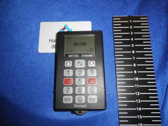
OOANRT302
Feb 02, 2015Nomad NRT302 Data Terminal
Equipment Class
DXX - Part 15 Low Power Communication Device Transmitter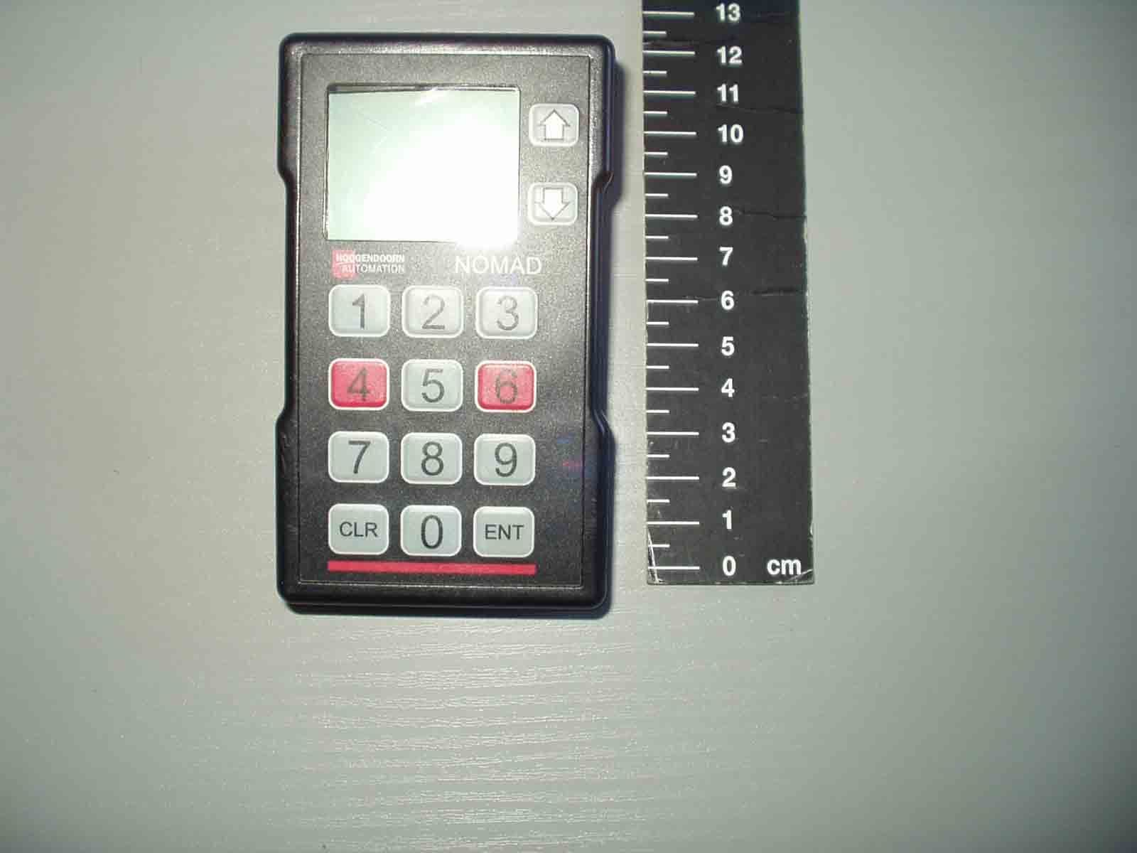
OOANRT202
Aug 15, 2007NOMAD NRT202 Data Terminal
Equipment Class
DXT - Part 15 Low Power Transceiver, Rx Verified
OOAW4-2
Feb 13, 2002NOMAD W4-2 Weighscale System
Equipment Class
DXX - Part 15 Low Power Communication Device Transmitter
OOANRT102-2
Oct 03, 1999Data Terminal
Equipment Class
DXT - Part 15 Low Power Transceiver, Rx Verified