OOANRT102-2Data Terminal
Maynetronics Ltd
Click to zoom
Application Details
- Equipment Class
- DXT - Part 15 Low Power Transceiver, Rx Verified
- Date of Grant
- Oct 03, 1999
- Application Purpose
- Original Equipment
- Date of Application
- Aug 12, 1999
- Equipment Note
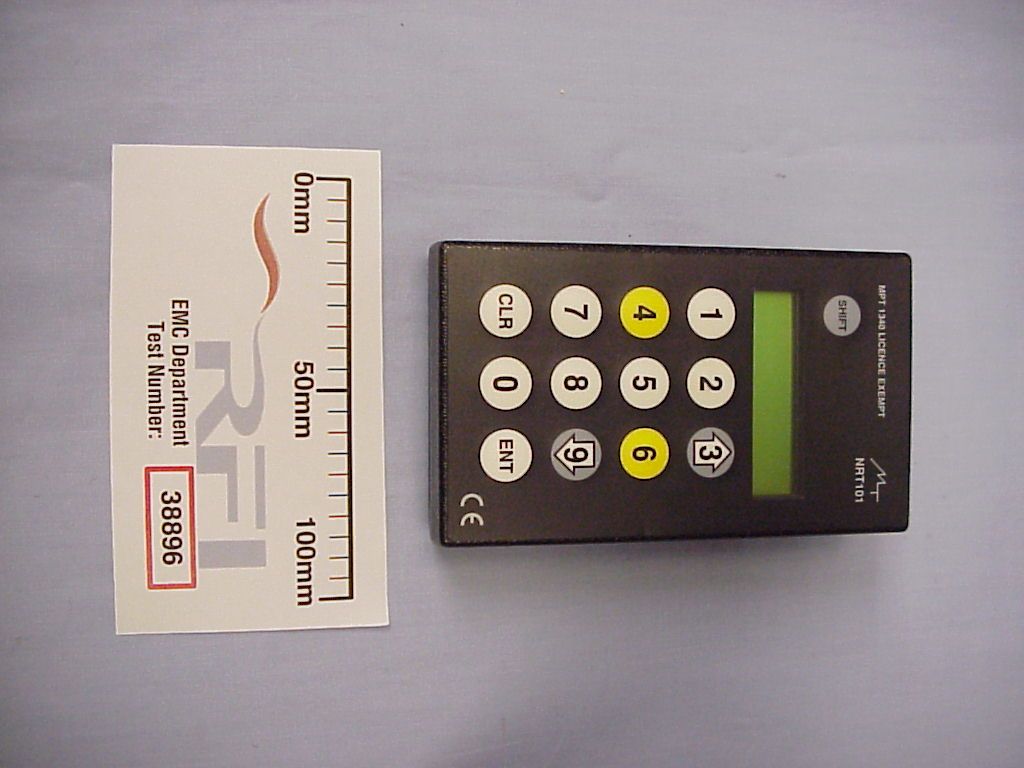
- Data Terminal
- Frequency Range
- 916.50000000 - 916.50000000
- Company
- Maynetronics Ltd
- Country
- United Kingdom
Documents & Files
Document Text
Text extracted from the exhibit documents filed with the FCC. Open a document above to read the original.
Users Manual
OPERATION MANUAL FOR NRT102 DATA TERMINAL NOMAD™ - NRT102 O PERATING INSTRUCTIONS PAGE 2 of 10 1. CERTIFICATION .....................................................................................................................3 2. INTRODUCTION .....................................................................................................................3 3. SETTING UP A TERMINAL FOR FIRST USE.........................................................................4 3.1 ENTERING A NODE NUMBER ........................................................................................................... 4 3.2 CHANGING OPERATING MODES ..................................................................................................... 5 4. THE LCD SCREEN .................................................................................................................5 4.1 STARTUP MESSAGE ......................................................................................................................... 5 4.2 STANDBY MODE ................................................................................................................................ 5 4.3 PAGING FACILITY .............................................................................................................................. 6 4.4 FEEDBACK.......................................................................................................................................... 7 4.5 MULTI-USER ....................................................................................................................................... 7 5. ENTERING DATA....................................................................................................................7 5.1 NORMAL MODE.................................................................................................................................. 7 5.2 MULTI-USER MODE ........................................................................................................................... 8 6. ERROR MESSAGES...............................................................................................................8 6.1 CLOCK NOT SET ................................................................................................................................ 8 6.2 FLAT BATTERY .................................................................................................................................. 9 6.3 MEMORY FULL ................................................................................................................................... 9 7. CHARGING .............................................................................................................................9 8. MAINTAINENCE AND CARE ................................................................................................ 10 8.1 CLEANING......................................................................................................................................... 10 8.2 BATTERIES ....................................................................................................................................... 10 8.3 KEYPAD ............................................................................................................................................ 10 NOMAD™ - NRT102 O PERATING INSTRUCTIONS PAGE 3 of 10 1. CERTIFICATION This device complies with part 15 of the FCC rules. Operation is subject to the following two conditions: (1) this device may not cause harmful interference, and (2) this device must accept any interference received, including interference that may cause undesired operation. 2. INTRODUCTION The NRT102 data terminal is a hand-held wireless keypad and display for entry of numeric data. This terminal provides the primary data entry method of the NOMAD system. Data entry is guided by menus displayed on the 16 character by 2 line display. The terminal is powered by a rechargeable battery with a built in charger that draws DC power from a charging adapter. In an emergency the rechargeable battery may be replaced by a standard PP3 providing no attempt is made to charge the unit while fitted with the non-rechargeable battery. The terminal does not have to be in radio range for data entry to take place. All data entered is stored in the terminals own memory (the memory is maintained even if the battery is discharged) and then sent to the NOMAD system whenever there is a good communication link. To the operator this is a seamless process. This is a key strength of the NOMAD system - essential operation is guaranteed regardless of sporadic radio interference. NOMAD™ - NRT102 O PERATING INSTRUCTIONS PAGE 4 of 10 3. SETTING UP A TERMINAL FOR FIRST USE Before a terminal can be used on the NOMAD network it must be assigned a node number so that the system can distinguish it from other terminals in the system. This will also clear the memory of the terminal and inform the system that all relevant menus should be loaded into the terminal. 3.1 ENTERING A NODE NUMBER After inserting a battery or removing the terminal from its charging bracket a startup message is displayed. While this message is displayed hold the 3 and the 9 keys down until prompted with the message “Enter node”. The node number is entered as 5 decimal digits xyzzz zzz = the node number. y = the language. x = the system number. The node number itself can be in the range 1 to 199. It is these three digits that identify the terminal on the system. The language number can be in the range 0 to 3 and indicates which language the menus should be. The default system language is 0. Additional languages (up to three) can be defined in the system setup for NOMAD and individual nodes then initialised to one of these. This way employees of different languages may work on the system side by side. Note that to change language the terminal has to re-initialised and its memory cleared as ab…
Text truncated - open the document above for the full version.
Operational Description
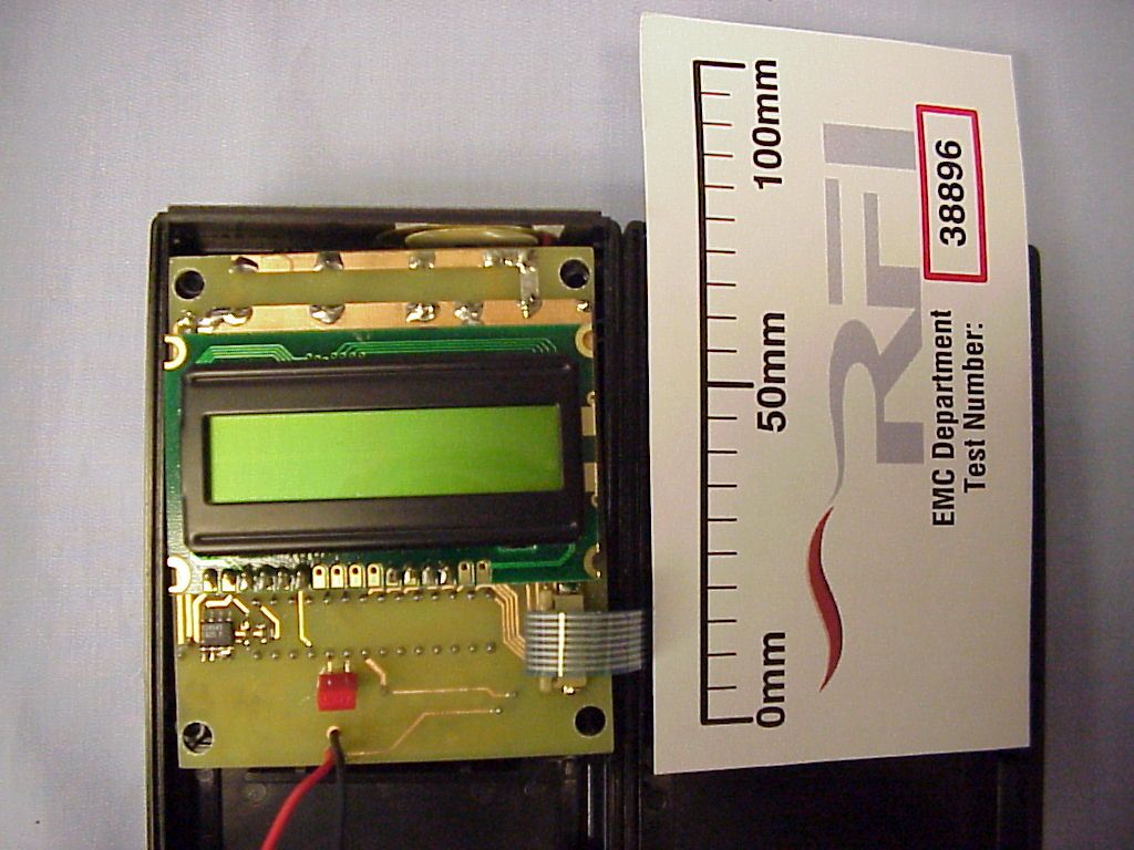
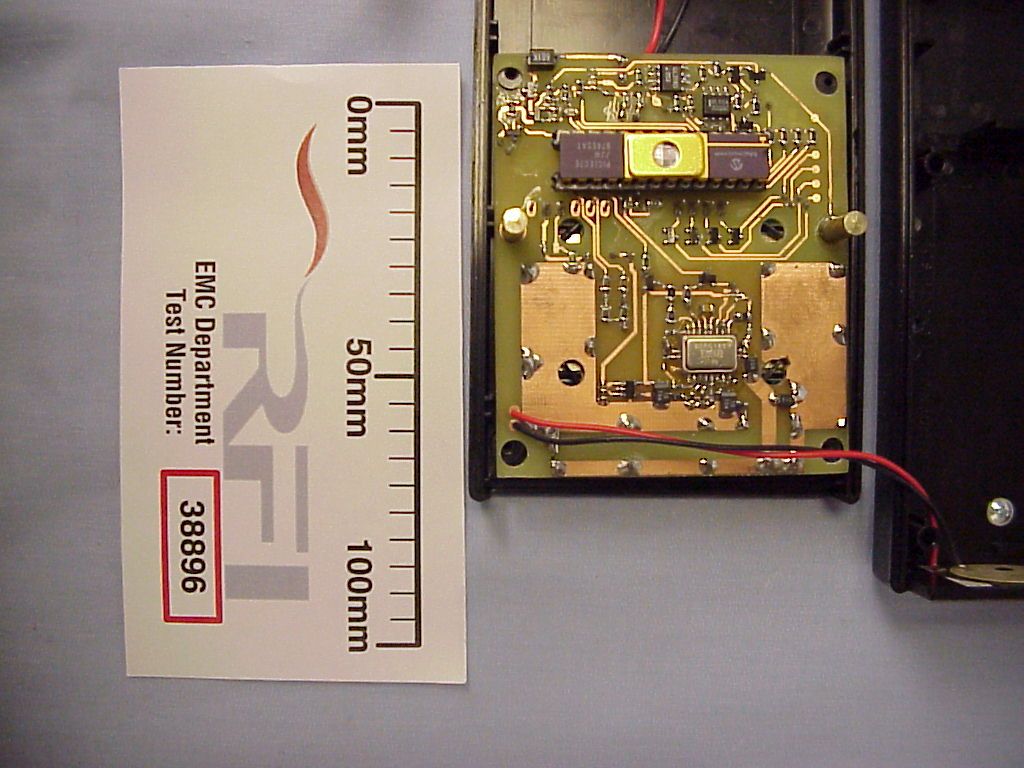
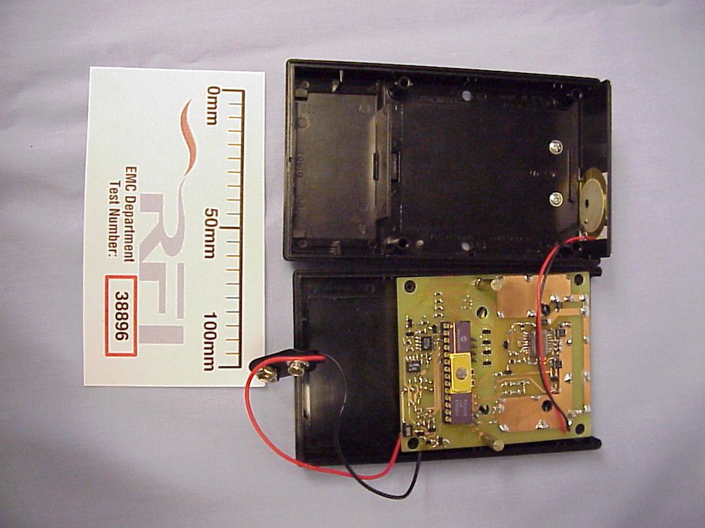
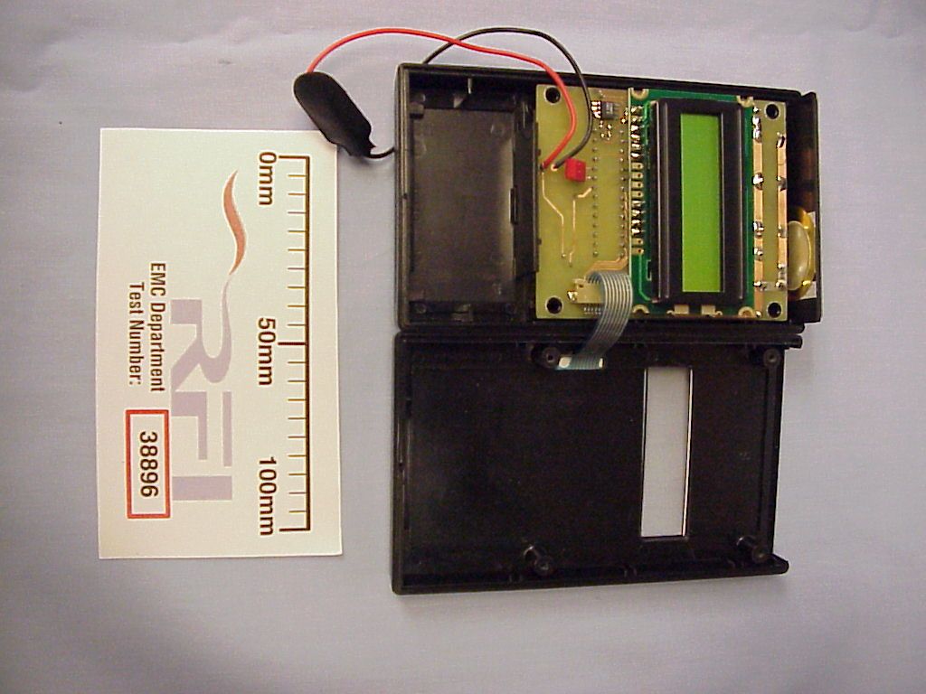
TECHNICAL DECRIPTION FOR NOMAD NRT102-2 TERMINAL The NOMAD system comprises a PC, a controller, multiple link units and terminals. The controller connects to the PC via a RS232 link. A RS485 bus connects the controller to the link units. Each link unit has a low powered UHF transceiver which communicates with the terminals. The number of link units depends on the size of the site. The aim of the whole system is to get data from the terminals onto the PC. The NRT102-2 terminal is a battery powered device consisting of a numeric keypad, a 2 line by 16 character reflective LC display and a wireless link to the NOMAD system. Data entry is guided by menus which are downloaded from the NOMAD system. The terminal is optimized for job logging of personnel and is essentially an electronic time sheet. A small embedded processor with a 1MHz clock provides all the peripheral and control features. An on-chip UART interfaces to the RF section. Data and menus are stored a 64k bit serial EEPROM with an I 2 C interface to the processor. The 4x4 matrix keypad is connected to the processors peripheral pins with the strobe lines sharing the same pins as the data bus for the display. A piezo sounder provides audible response to keypad presses and other abbuciations. Power is supplied from a 8.4 volt NiMH rechargeable battery which is recharged under the control of the processor. The battery is followed by a linear regulator which steps the voltage down to 5 volts. An op-amp and a few discrete components form the charging circuit which charges at 3mA or 22mA. The wireless section is centered around a TR1000 hybrid transceiver from Radio Monolithics. This device contains all the necessary RF circuitry with just a few passive components, a 3.3V regulator, and a couple of transistors to perform level shifting of the logic signals. The antenna is a loop type integral to the PCB. Operating frequency is 916.5 MHz and the modulation type is OOK.
Test Report
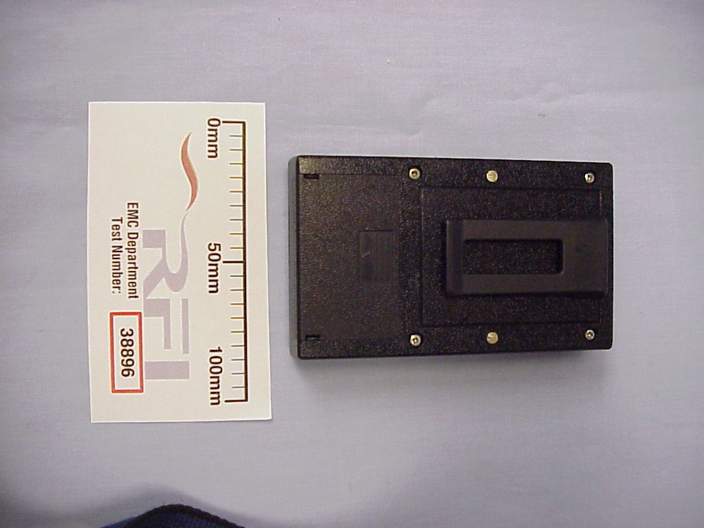
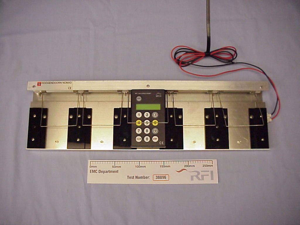
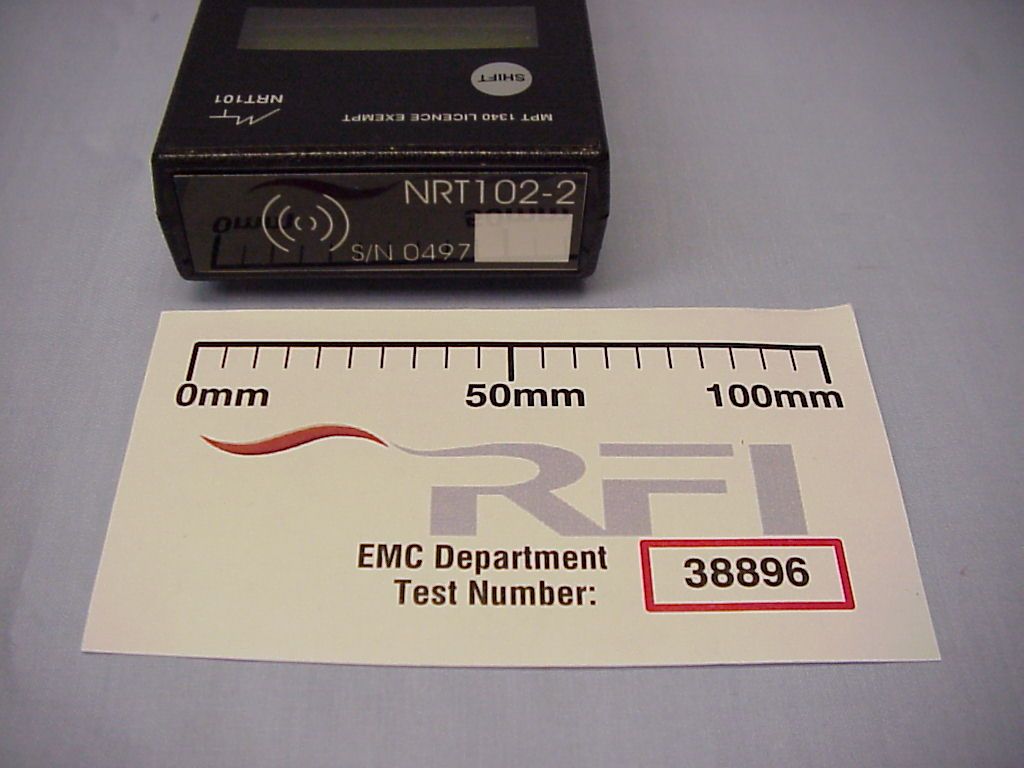
Radio Frequency Investigation Ltd, Ewhurst Park, Ramsdell, Basingstoke, Hampshire, RG26 5RQ, ENGLAND. Tel: +44 (0) 1256 851193 Fax: +44 (0) 1256 851192 Registered in England, No. 211 7901. Registered Office: Ewhurst Park, Ramsdell, Basingstoke, Hampshire RG26 5RQ TESTING 0644 TEST REPORT FROM RADIO FREQUENCY INVESTIGATION LTD. Test Of: Maynetronics Ltd. NTR102-2 Data Terminal. To: FCC Part 15 Subpart C: 1998 (Intentional Radiators) Section 15.249 Test Report Serial No: RFI/EMCB1/RP38896A This Test Report Is Issued Under The Authority Of Brian Watson Technical Director: Checked By: Tested By:Release Version No: PDF01 Issue Date: 5 August 1999Test Date: 21 May 1999 to 4 June 1999 This report is issued in Adobe Acrobat portable document format (PDF). It is only a valid copy of the report if it is being viewed in PDF format with the following security options not allowed: Changing the document, Selecting text and graphics, Adding or changing notes and form fields. Furthermore, the date of creation must match the issue date stated above. This report may be copied in full. RADIO FREQUENCY INVESTIGATION LTD.TEST REPORT S.No: RFI/EMCB1/RP38896A EMC DepartmentPage 2 of 34 Issue Date: 5 August 1999 Test Of:Maynetronics Ltd. NTR102-2 Data Terminal. To:F.C.C. Part 15: 1998 Class B This page has been left intentionally blank. RADIO FREQUENCY INVESTIGATION LTD.TEST REPORT S.No: RFI/EMCB1/RP38896A EMC DepartmentPage 3 of 34 Issue Date: 5 August 1999 Test Of:Maynetronics Ltd. NTR102-2 Data Terminal. To:F.C.C. Part 15: 1998 Class B Table of Contents 1. Client Information......................................................................................................4 2. Equipment Under Test (EUT).....................................................................................5 3. Test Specification, Methods And Procedures..........................................................9 4. Deviations From The Test Specification.................................................................10 5. Operation Of The EUT During Testing....................................................................11 6. Summary Of Test Results........................................................................................12 7. Measurements, Examinations And Derived Results..............................................13 8. Measurement Uncertainty........................................................................................21 Appendix 1. Test Equipment Used...............................................................................22 Appendix 2. Measurement Methods............................................................................23 Appendix 3. Test Configuration Drawings..................................................................26 Appendix 4. Graphical Test Results............................................................................30 Appendix 5 Photographs of EUT..................................................................................33 RADIO FREQUENCY INVESTIGATION LTD.TEST REPORT S.No: RFI/EMCB1/RP38896A EMC DepartmentPage 4 of 34 Issue Date: 5 August 1999 Test Of:Maynetronics Ltd. NTR102-2 Data Terminal. To:F.C.C. Part 15: 1998 Class B 1. Client Information Company Name: Maynetronics Ltd. Address: 34 St Thomas Street Ryde Isle of Wight PO33 2DL Contact Name: Mr G Mayne. RADIO FREQUENCY INVESTIGATION LTD.TEST REPORT S.No: RFI/EMCB1/RP38896A EMC DepartmentPage 5 of 34 Issue Date: 5 August 1999 Test Of:Maynetronics Ltd. NTR102-2 Data Terminal. To:F.C.C. Part 15: 1998 Class B 2. Equipment Under Test (EUT) The following information (with the exception of the Date of Receipt) has been supplied by the client: 2.1. Identification Of Equipment Under Test (EUT) Brand Name: Maynetronics Ltd Model Name or Number: NRT102-2 Unique Type Identification: NRT102-2 Serial Number: 0497 Country of Manufacture: None stated by client FCC ID Number: Awaiting Certification from the FCC. Date of Receipt: 21 May 1999 RADIO FREQUENCY INVESTIGATION LTD.TEST REPORT S.No: RFI/EMCB1/RP38896A EMC DepartmentPage 6 of 34 Issue Date: 5 August 1999 Test Of:Maynetronics Ltd. NTR102-2 Data Terminal. To:F.C.C. Part 15: 1998 Class B 2.2. Description Of EUT The NOMAD system comprises a PC, a controller, multiple link units and terminals. The controller connects to the PC via a RS232 link. A RS485 bus connects the controller to the link units. Each link unit has a low powered UHF transceiver which communicates with the terminals. The number of link units depends on the size of the site. The aim of the whole system is to get data from the terminals onto the PC. The NRT102-2 terminal is a battery powered device consisting of a numeric keypad, a 2 line by 16 character reflective LC display and a wireless link to the NOMAD system. Data entry is guided by menus which are downloaded from the NOMAD system. The terminal is optimised for job logging of personnel and is essentially an electronic time sheet. A small embedded processor with a 1MHz clock provides all the peripheral and control features. An on-chip UART interfaces to the RF section. Data and menus are stored a 64k bit serial EEPROM with an I 2 C interface to the processor. The 4x4 matrix keypad is connected to the processors peripheral pins with the strobe lines sharing the same pins as the data bus for the display. A piezo sounder provides audible response to keypad presses and other abbuciations. Power is supplied from a 8.4 volt NiMH rechargeable battery which is recharged under the control of the processor. The battery is followed by a linear regulator which steps the voltage down to 5 volts. An op-amp and a few discrete components form the charging circuit which charges at 3mA or 22mA. The wireless section is centred around a TR1000 hybrid transceiver from Radio Monolithics. This device contains all the necessary RF circuitry with just a few passive components, a 3.3V regulator, and a couple of transistors to perform level shifting of the logic si…
Text truncated - open the document above for the full version.
Test Report
16 August, 1999 Subject: FCC ApplicationFCC ID OOANRT-102-2 EA95136 Our Ref: Maynetronics Dear Sir, We would like to change the product ID from NRT-102-2 to NRT102-2 thus giving a full FCC ID of OOANRT102-2. The “dash” between the T and the 1 was an error. Thank you for your help in this matter. Yours sincerely N.G. Cobb Senior Engineer Regulatory and Technical Support Group
Contact Information
Applicant
Mr. George Mayne
Technical Contact
Radio Frequency Investigation LtdNicholas G Cobb
[email protected]+44 1256 855472
Ewhurst Park · Basingstoke · United Kingdom
Test Firm
Radio Frequency Investigation Ltd.Joe Wilkinson
- -
Technical Specifications
| # | Rule Parts | Frequency Range | Power Output |
|---|---|---|---|
| 1 | 15C | 916.5 MHz - 916.5 MHz | - |
Other Applications from Maynetronics Ltd
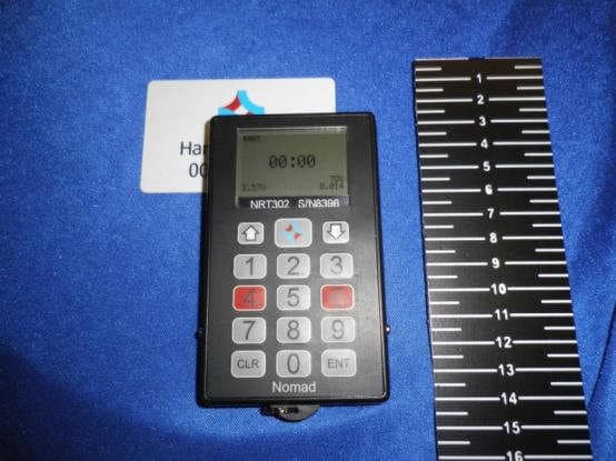
OOANRT302
Feb 02, 2015Nomad NRT302 Data Terminal
Equipment Class
DXX - Part 15 Low Power Communication Device Transmitter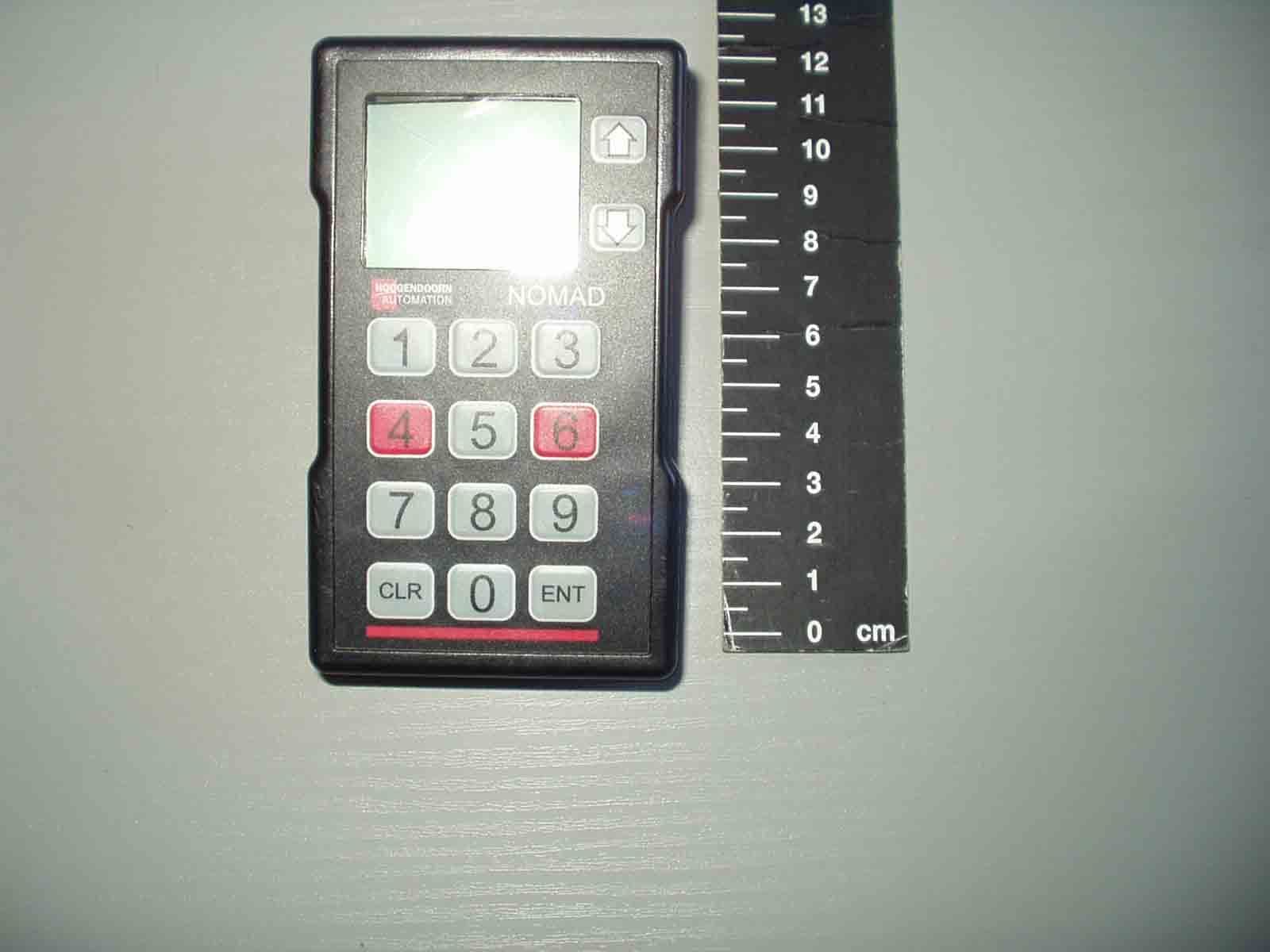
OOANRT202
Aug 15, 2007NOMAD NRT202 Data Terminal
Equipment Class
DXT - Part 15 Low Power Transceiver, Rx Verified
OOAW4-2
Feb 13, 2002NOMAD W4-2 Weighscale System
Equipment Class
DXX - Part 15 Low Power Communication Device Transmitter
OOALK3A-2
Oct 05, 1999LK3A-2 Link Unit
Equipment Class
DXT - Part 15 Low Power Transceiver, Rx Verified