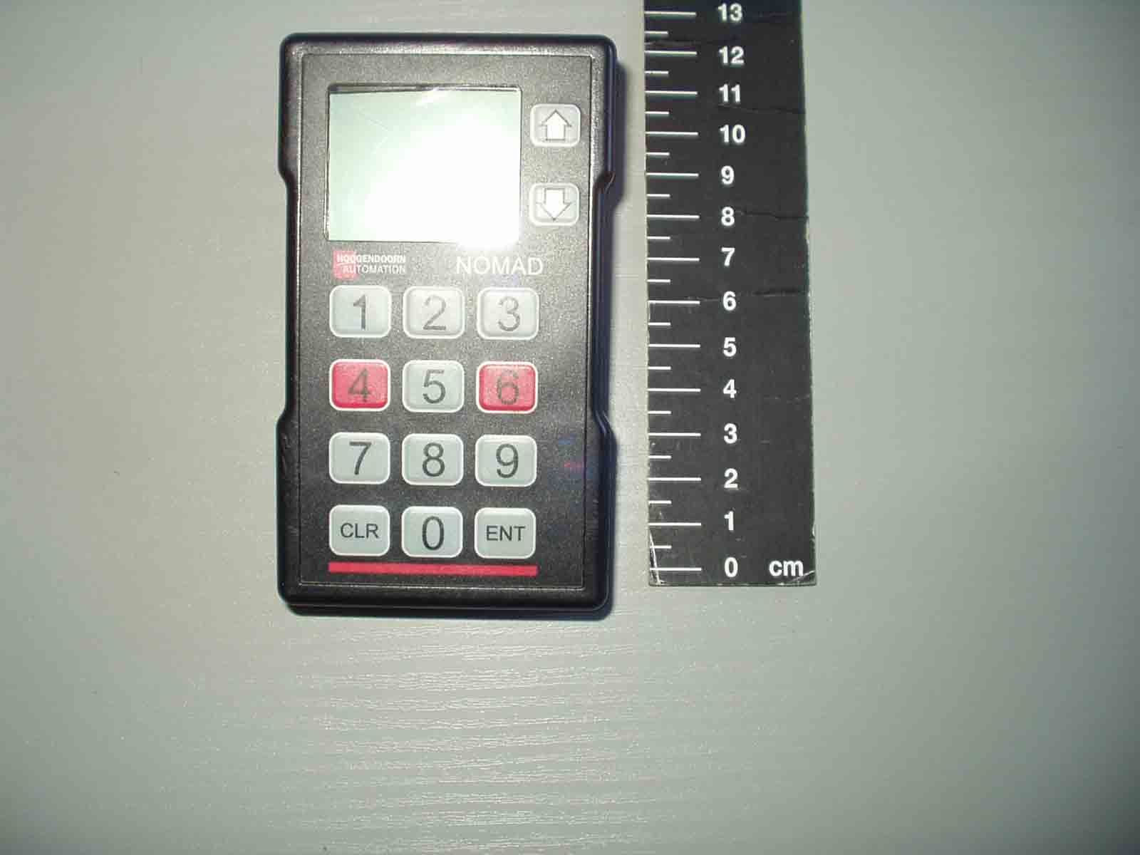
OOANRT202NOMAD NRT202 Data Terminal
Maynetronics Ltd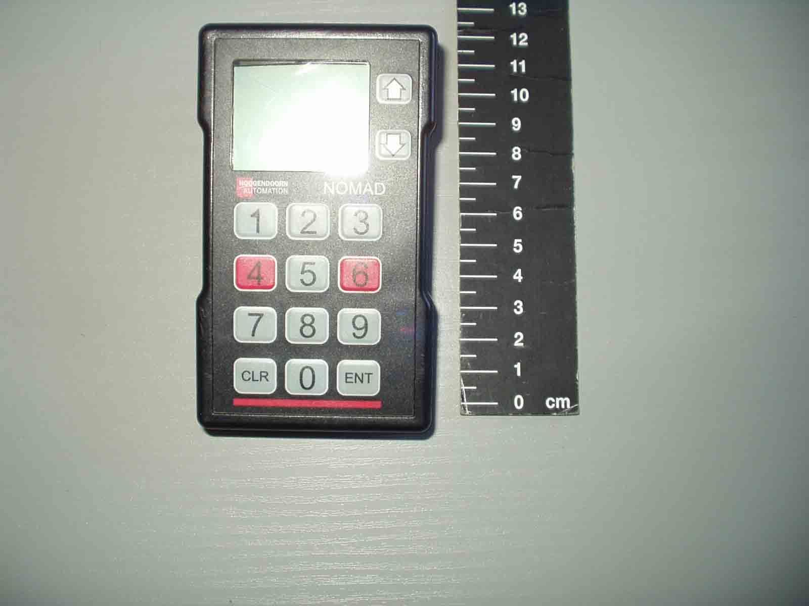
Click to zoom
Application Details
- Equipment Class
- DXT - Part 15 Low Power Transceiver, Rx Verified
- Date of Grant
- Aug 15, 2007
- Application Purpose
- Original Equipment
- Date of Application
- Aug 15, 2007
- Equipment Note
- NOMAD NRT202 Data Terminal
- Frequency Range
- 915.00000000 - 915.00000000
- Company
- Maynetronics Ltd
- Country
- United Kingdom
Documents & Files
Document Text
Text extracted from the exhibit documents filed with the FCC. Open a document above to read the original.
Users Manual
OPERATION MANUAL FOR NRT202 DATA TERMINAL NOMAD - NRT202 O PERATING I NSTRUCTIONS P AGE 2 of 2 1. IMPORTANT INFORMATION ...............................................................................................3 2. INTRODUCTION...................................................................................................................3 3. SETTING UP A TERMINAL FOR FIRST USE......................................................................4 3.1 ENTERING A NODE NUMBER................................................................................................... 4 3.2 CHANGING OPERATING MODES..............................................................................................5 4. THE LCD SCREEN...............................................................................................................5 4.1 STARTUP MESSAGE..................................................................................................................5 4.2 STANDBY MODE.........................................................................................................................6 4.3 PAGING FACILITY.......................................................................................................................7 4.4 FEEDBACK.................................................................................................................................. 7 4.5 MULTI-USER................................................................................................................................8 5. ENTERING DATA.................................................................................................................8 5.1 NORMAL MODE..........................................................................................................................8 5.2 MULTI-USER MODE....................................................................................................................9 6. BARCODE ENTRIES............................................................................................................9 6.1 WARNING TONES.....................................................................................................................10 6.2 BARCODE TYPES.....................................................................................................................10 6.3 MAKING AN ENTRY..................................................................................................................11 6.4 KEYPAD ENTRIES....................................................................................................................11 6.5 BARCODE ONLY MODE...........................................................................................................12 6.6 SUN SHIELD..............................................................................................................................12 7. ERROR MESSAGES...........................................................................................................12 7.1 CLOCK NOT SET.......................................................................................................................12 7.2 FLAT BATTERY.........................................................................................................................12 7.3 MEMORY FULL..........................................................................................................................13 8. CHARGING.........................................................................................................................13 9. MAINTAINENCE AND CARE..............................................................................................14 9.1 CLEANING................................................................................................................................. 14 9.2 BATTERIES................................................................................................................................14 9.3 KEYPAD.....................................................................................................................................14 10. SPECIFICATION.............................................................................................................14 10.1 C OMMUNICATION R ANGE ...............................................................................................................15 NOMAD - NRT202 O PERATING I NSTRUCTIONS P AGE 3 of 3 1. IMPORTANT INFORMATION FCC ID: OOANRT202 This device complies with part 15 of the FCC rules. Operation is subject to the following two conditions: (1) This device may not cause harmful interference, and (2) this device must accept any interference received, including interference that may cause undesired operation. Warning! Any modification or changes made to this device, unless explicitly approved by Maynetronics Limited, will invalidate the authorisation of this device. Operation of an unauthorised device is prohibited under Section 302 of the Communications Act of 1934, as amended, and Subpart I of Part 2 of Chapter 47 of the code of Federal Regulations. 2. INTRODUCTION The NRT202 data terminal is a hand-held wireless keypad and display for entry of numeric data. This terminal provides the primary data entry method of the NOMAD system. Data entry is guided by menus displayed on the graphic display. The terminal is powered by rechargeable batteries with a built in charger that draws DC power from a charging adapter. In an emergency, the rechargeable battery may be replaced by standard alakaline batteries providing no attempt is made to charge the unit while fitted with the non- rechargeable battery. The terminal does not have to be in radio range for data entry to take place. All data entered is stored in the terminals own memory (the memory is maintained even if the battery is discharged) and then sent to the NOMAD system whenever there is a good communication link. To the operator this is a seamless process. …
Text truncated - open the document above for the full version.
Attestation Statements
Oak Cottage Ashey Road Ryde Isle of Wight PO33 4BD Tel: +44 (0)1983 564233 Fax: +44 (0)1983 617081 email: [email protected] web: www.maynetronics.com Directors: G Mayne, K Mayne. Regd. Office: Oak Cottage, Ryde, IW. Company Number 2872044. VAT Number 615416361 5 th July, 2007 TRL Compliance Services Ltd Long Green Forthampton Gloucester GL19 4QH UK To Whom It May Concern: We certify that we are not subject to denial of federal benefits, that includes FCC benefits, pursuant to Section 5301 of the Anti-Drug Abuse ACT of 1988, U.S.C. 862. Further, no party, as defined in 47 CFR 1.2002(b), to the application is subject to denial of federal benefits, that includes FCC benefits. Thank you for your attention to this matter. Thank you for your attention to these matters. Yours faithfully Maynetronics Limited George Mayne
Cover Letter(s)
Oak Cottage Ashey Road Ryde Isle of Wight PO33 4BD Tel: +44 (0)1983 564233 Fax: +44 (0)1983 617081 email: [email protected] web: www.maynetronics.com Directors: G Mayne, K Mayne. Regd. Office: Oak Cottage, Ryde, IW. Company Number 2872044. VAT Number 615416361 Request for Confidentiality In Accordance with FCC Rule 0.459 1 st May, 2007 TRL Compliance Services Ltd Long Green Forthampton Gloucester GL19 4QH UK RE: Certification Application FCC ID: OOALK4-2 and OOANRT202 To Whom It May Concern: Please be advised that the following information is to be held confidential on behalf of Maynetronics Limited. Schematics Parts lists The application contains technical information which Maynetronics Limited deems to be trade secrets and propriety. If made public, the information might be used to the disadvantage of the applicant in the market place. Thank you for your attention to this matter. Yours faithfully Maynetronics Limited George Mayne
ID Label/Location Info
NRT202 S/Nxxxx FCC ID OOANRT202 IC: XXX-YYY
Operational Description
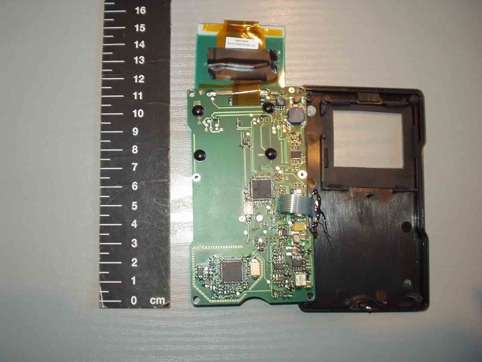
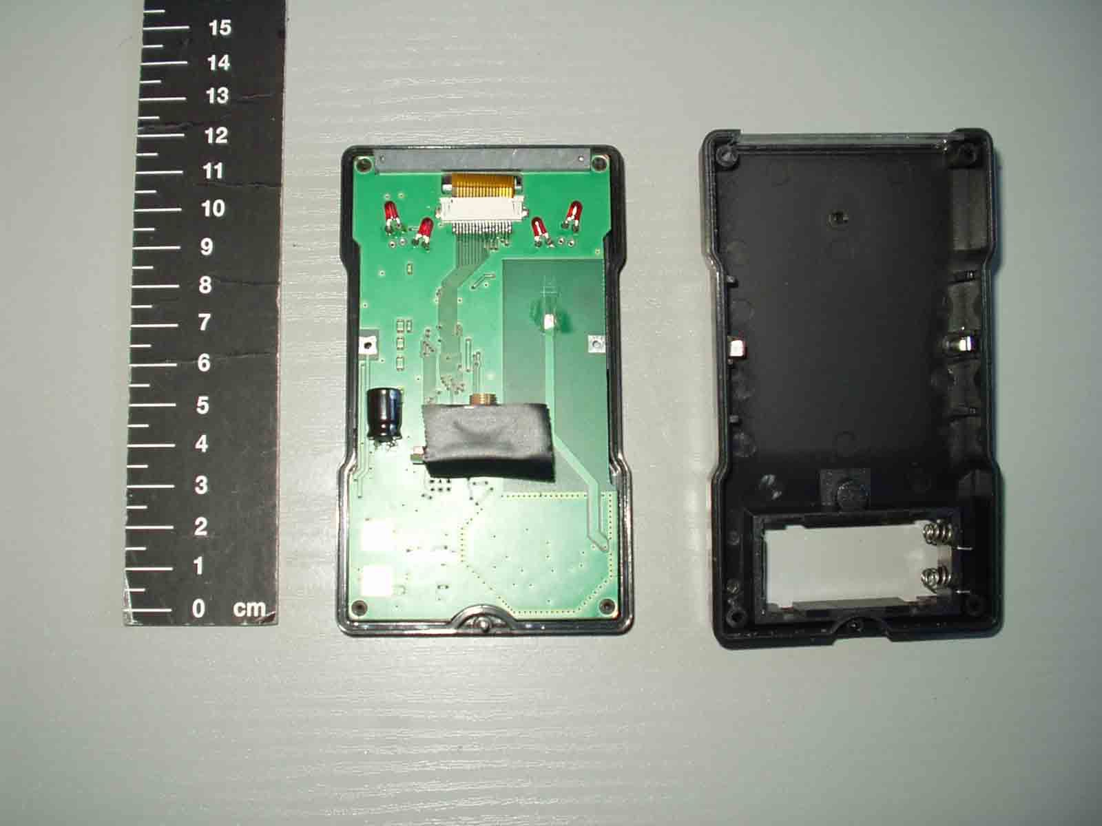
NOMAD Overview General The Nomad system uses a wireless battery powered terminal (NRT202) and a 12V DC powered base station (LK4-2 Link Unit) to gather manually entered data about personnel activity. The system is primarily target at commercial horticulture. Communication between the two devices is via a 915MHz low power FM radio signal. All communication is initiated by the link unit to which the terminal then makes a response. NRT202 Terminal The terminal has a numeric keypad and a CCD type barcode reader for data input, along with an LCD display for operator feedback. Up to 231 terminals may be deployed on one network. The CPU is a PIC18LF4520 running at 8MHz. All entered data is buffered in a 256k I 2 C EEPROM in case the terminal is out of range of the link unit. The radio link uses a XE1202A from Semtech with a PCB antenna. Power is provided by two NiMH cells that are sufficient to allow an operational time greater than 12 hours in normal use. A 9-18V DC charging input allows the cells to be charged without removing them. LK4-2 Link Unit The link unit connects to a RS485 bus and passes correctly formatted messages to the terminal, waits for a response and returns that on the bus. The CPU is a PIC18LF2520 running at 8MHz. The radio link uses a XE1202A from Semtech with a ¼ wave whip antenna. Power is form an external 12V DC supply and the processor power is derived from an isolated DC-DC converter. The RS485 bus drivers are powered by a linear regulator directly from the external supply. Signals to/from the RS485 driver are optically coupled to increase noise immunity. Multiple link units (maximum 32) may be connected to the same bus, the address of each is set by a DIP switch.
Test Report
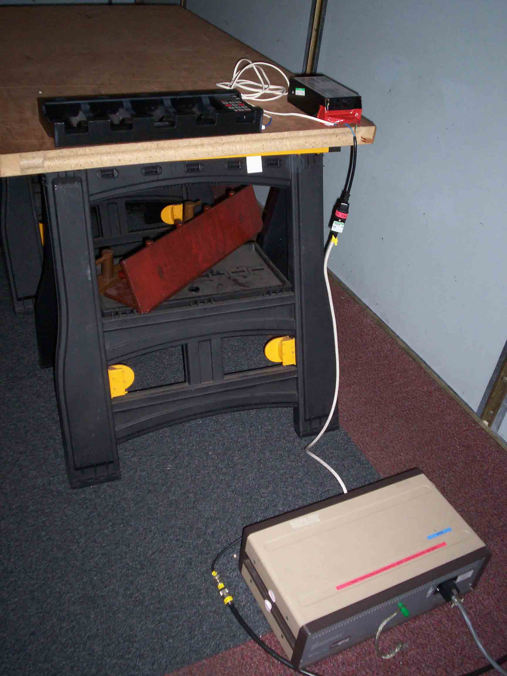
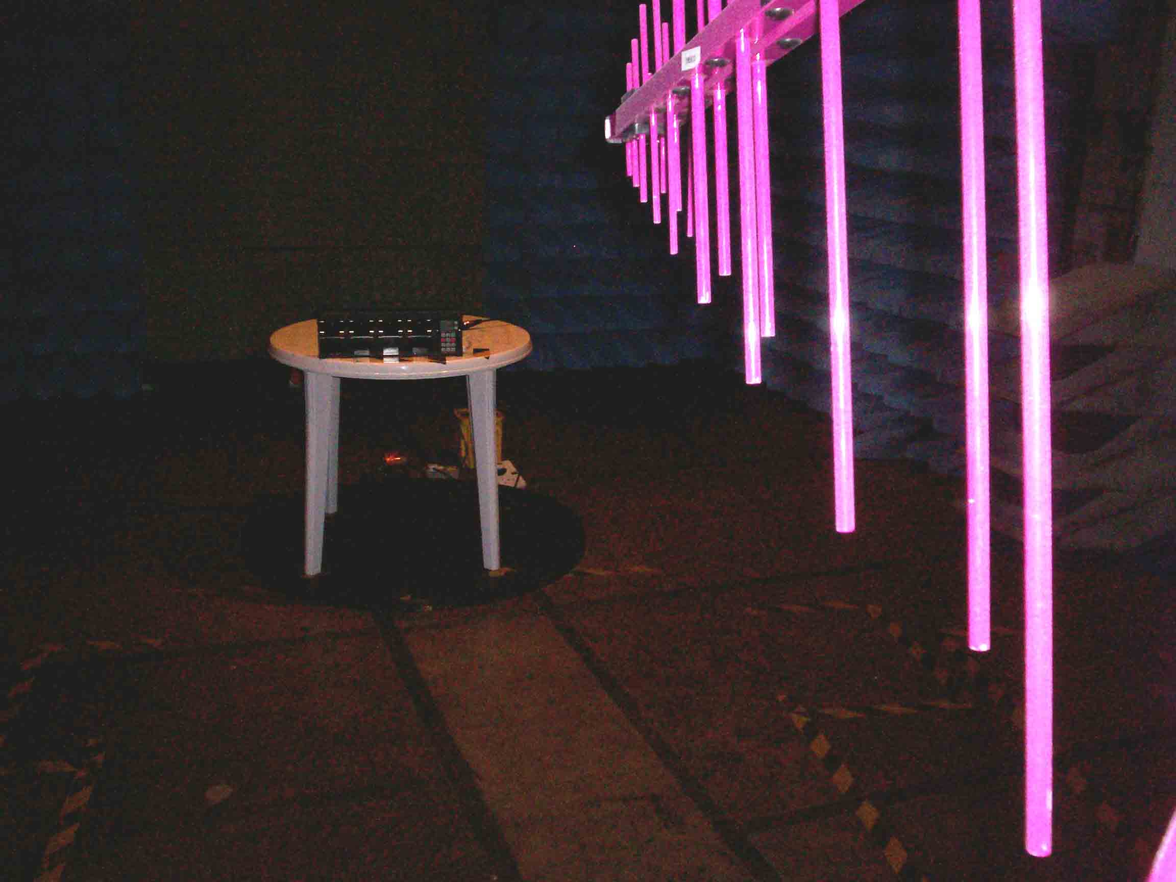
File name MAYNETRONIC.190A PAGE 1 OF 51 QMF21 – 8: FCC PART 15C: RNE ISSUE 03: - JUL 07 FCC Test Report for Wireless Data Terminal NRT202 Report Number 07-190/3228/2/07A Report Produced by: - R.N. Electronics Ltd. 1 Arnolds Court Arnolds Farm Lane Mountnessing ESSEX CM13 1UT www.RNelectronics.com Telephone 01277 352219 Facsimile 01277 352968 EMC & RADIO TEST SERVICES S RN Electronics ©2004 RN ELECTRONICS LIMITED REPORT NUMBER 07-190/3228/2/07A ALL RIGHTS RESERVED File name MAYNETRONIC.190A PAGE 2 OF 51 QMF21 – 8: FCC PART 15C: RNE ISSUE 03: - JUL 07 1. Contents 1. CONTENTS........................................................................................................................................... 2 2. S UMMARY OF TEST RESULTS............................................................................................................. 3 3. INFORMATION ABOUT EQUIPMENT UNDER TEST............................................................................... 4 3.1 C ONFIGURATION DIAGRAM................................................................................................................ 5 4. SPECIFICATIONS.................................................................................................................................. 6 5. T ESTS, METHODS AND RESULTS........................................................................................................ 7 5.1 Conducted Emissions............................................................................................................ 7 5.2 Radiated Emissions............................................................................................................... 8 5.3 Intentional Radiator Field Strength ...................................................................................... 9 5.4 Frequency Tolerance .......................................................................................................... 10 5.5 Modulation Bandwidth (Band Edges) ................................................................................ 10 6. PLOTS AND RESULTS......................................................................................................................... 11 6.1 Conducted Emissions.......................................................................................................... 11 6.2 Radiated Emissions............................................................................................................. 19 6.3 Intentional Radiator Field Strength .................................................................................... 39 6.4 Modulation Bandwidth .......................................................................................................39 7 E XPLANATORY NOTES...................................................................................................................... 40 7.1 Explanation of FAIL LIMIT 1 Statement........................................................................... 40 7.2 Explanation of limit line calculations for radiated measurements ...................................... 40 8. P HOTOGRAPHS.................................................................................................................................. 41 9. SIGNAL LEADS................................................................................................................................... 47 10. T EST EQUIPMENT CALIBRATION LIST............................................................................................... 48 11. A UXILIARY EQUIPMENT.................................................................................................................... 49 11.1 Auxiliary equipment supplied by Maynetronics Ltd .......................................................... 49 11.2 Auxiliary equipment supplied by RN Electronics Limited................................................. 49 12. M ODIFICATIONS................................................................................................................................50 13. Compliance information .....................................................................................................51 ©2004 RN ELECTRONICS LIMITED REPORT NUMBER 07-190/3228/2/07A ALL RIGHTS RESERVED File name MAYNETRONIC.190A PAGE 3 OF 51 QMF21 – 8: FCC PART 15C: RNE ISSUE 03: - JUL 07 2. Summary of Test Results The Wireless Data Terminal NRT202 was tested to the following standards: - FCC Part 15C (effective date October 7, 2006); Class DXT Intentional Radiator Any compliance statements are made reliant on the modes of operation as instructed to us by the Manufacturer based on their specific knowledge of the application and functionality of the equipment tested. Title Reference Results 1. Conducted Emissions FCC Part 15C §15.207 PASSED 2. Radiated Emissions FCC Part 15C §15.205, §15.209, §15.249(a) and §15.249(d) PASSED 3. Modulation Bandwidth FCC Part 15C §15.215(c) PASSED 4. Intentional Radiator Field Strength FCC Part 15C §15.249(a) PASSED 5. Frequency Tolerance FCC Part 15C §15.249(b) NOT APPLICABLE¹ ¹ No specification requirement for this type of equipment. Test only applicable to point-to-point equipment. This report relates to the equipment tested as identified by a unique serial number and at the time it was tested. It does not relate to any other similar equipment and performance of the product before or after the test cannot be guaranteed. Date of Test: 22/Nov/06 Test Engineer: Approved By: Customer Representative: ©2004 RN ELECTRONICS LIMITED REPORT NUMBER 07-190/3228/2/07A ALL RIGHTS RESERVED File name MAYNETRONIC.190A PAGE 4 OF 51 QMF21 – 8: FCC PART 15C: RNE ISSUE 03: - JUL 07 3. Information about Equipment Under Test Applicant Maynetronics Ltd Oak Cottage Ashey Road Ashey Isle of Wight PO33 4BD Manufacturer/Brand Name Maynetronics Ltd Full name of EUT Wireless Data Terminal Model Number of EUT NRT202 Serial Number of EUT 5827 FCC ID (if applicable): OOANRT202 Date when equ…
Text truncated - open the document above for the full version.
Contact Information
Applicant
Mr. George Mayne
Test Firm
R.N. Electronics Ltd.Roger Ray
Technical Specifications
| # | Rule Parts | Frequency Range | Power Output |
|---|---|---|---|
| 1 | 15C | 915 MHz - 915 MHz | - |
Other Applications from Maynetronics Ltd
OOANRT302
Feb 02, 2015Nomad NRT302 Data Terminal
Equipment Class
DXX - Part 15 Low Power Communication Device Transmitter
OOAW4-2
Feb 13, 2002NOMAD W4-2 Weighscale System
Equipment Class
DXX - Part 15 Low Power Communication Device Transmitter
OOALK3A-2
Oct 05, 1999LK3A-2 Link Unit
Equipment Class
DXT - Part 15 Low Power Transceiver, Rx Verified
OOANRT102-2
Oct 03, 1999Data Terminal
Equipment Class
DXT - Part 15 Low Power Transceiver, Rx Verified