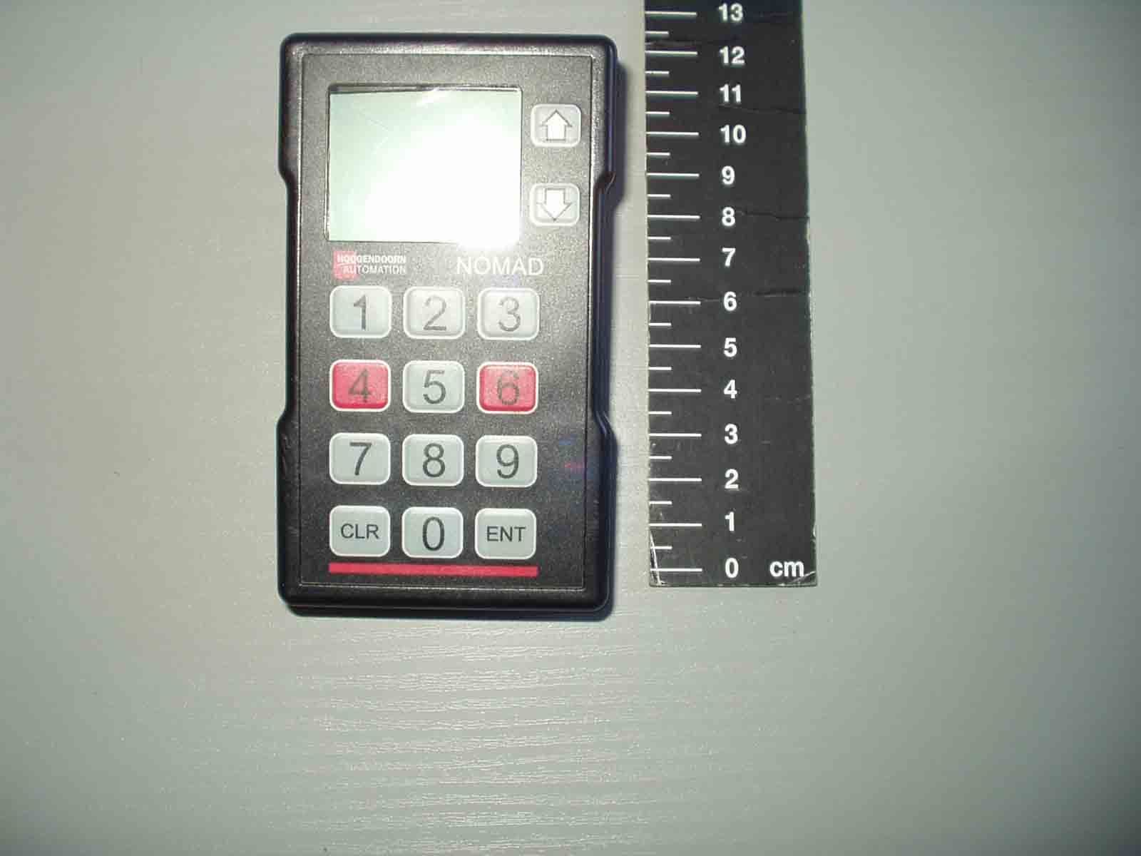
OOANRT302Nomad NRT302 Data Terminal
Maynetronics Ltd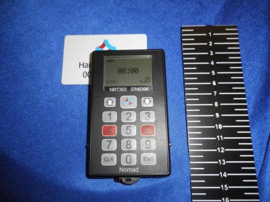
Click to zoom
Application Details
- Equipment Class
- DXX - Part 15 Low Power Communication Device Transmitter
- Date of Grant
- Feb 02, 2015
- Application Purpose
- Original Equipment
- Date of Application
- Feb 01, 2015
- Equipment Note
- Nomad NRT302 Data Terminal
- Frequency Range
- 13.56000000 - 13.56000000
- Company
- Maynetronics Ltd
- Country
- United Kingdom
Documents & Files
Document Text
Text extracted from the exhibit documents filed with the FCC. Open a document above to read the original.
Users Manual
OPERATION MANUAL FOR NRT302 DATA TERMINAL NOMAD™-NRT202 OPERATINGINSTRUCTIONS PAGE2 of15 1.IMPORTANT INFORMATION..................................................................................................... 3 2.INTRODUCTION .......................................................................................................................... 4 3.SETTING UP A TERMINAL FOR FIRST USE .......................................................................... 6 3.1ENTERINGANODENUMBER..................................................................................................6 3.2CHANGINGOPERATINGMODES ............................................................................................7 4.THE LCD SCREEN...................................................................................................................... 7 4.1STARTUPMESSAGE ...............................................................................................................7 4.2STANDBYMODE .....................................................................................................................8 4.3PAGINGFACILITY ...................................................................................................................9 4.4FEEDBACK..............................................................................................................................9 4.5MULTI-USER..........................................................................................................................10 5.ENTERING DATA ...................................................................................................................... 10 5.1NORMALMODE.....................................................................................................................10 5.2MULTI-USERMODE ..............................................................................................................11 6.RFID ENTRIES ........................................................................................................................... 11 6.1W ARNINGTONES .................................................................................................................11 6.2RFIDTYPES ..........................................................................................................................12 6.3MAKINGANENTRY ...............................................................................................................12 6.4KEYPADENTRIES.................................................................................................................12 6.5RFIDONLYMODE .................................................................................................................13 7.ERROR MESSAGES ................................................................................................................. 13 7.1CLOCKNOTSET ...................................................................................................................13 7.2FLATBATTERY......................................................................................................................13 7.3MEMORYFULL......................................................................................................................13 8.CHARGING................................................................................................................................. 14 9.MAINTAINENCE AND CARE ................................................................................................... 14 9.1BATTERIES ...........................................................................................................................14 9.2KEYPAD ................................................................................................................................15 10.SPECIFICATION .................................................................................................................... 15 10.1COMMUNICATIONRANGE............................................................................................................15 NOMAD™-NRT202 OPERATINGINSTRUCTIONS PAGE3 of15 1.IMPORTANT INFORMATION FCC ID:OOANRT302 IC:3539A-NRT302 Model: NRT302 The FCC and IC id’s can also be seen on the terminal’s LCD during start up or by pressing 5 and 0 for one second at any time. FCC Compliance W arning W ARNING: Changes or modifications to the transmitter not expressly approved by the manufacturer could void the user's authority to operate this RF device. FCC & IC Compliance Statement This device complies with Part 15 of the FCC Rules and Industry Canada licence exempt RSS standard(s). Operation is subject to the following two conditions: 1. This device may not cause interference, and 2. This device must accept any interference, including interference that may cause undesired operation of the device. Under Industry Canada regulations, this radio transmitter may only operate using an antenna of a type and maximum (or lesser) gain approved for the transmitter by Industry Canada. To reduce potential radio interference to other users, the antenna type and its gain should be so chosen that the equivalent isotropically radiated power (e.i.r.p.) is not more than that necessary for successful communication. IC Attestation de Conformité Le présent appareil est conforme à la partie 15 de la réglementation de la FCC et aux CNR d'Industrie Canada applicables aux appareils radio exempts de licence. L'exploitation est autorisée aux deux conditions suivantes: 1. L'appareil ne doit pas produire de brouillage, et 2. L'utilisateur de l'appareil doit accepter tout brouillage radioélectrique subi, NOMAD™-NRT202 OPERATINGINSTRUCTIONS PAGE4 of15 mêmesilebrouillageestsusceptibled'encompromettrele fonctionnement. Conformément à la réglementation d'Industrie Canada, le présent émetteur radio peut fonctionner avec une antenne d'un type et d'un gain maximal (ou inférieur) approuvé pour l'émetteur par Industrie Canada. Dans le but de réd…
Text truncated - open the document above for the full version.
Cover Letter(s)
Directors: G Mayne, K Mayne. Regd. Office: Oak Cottage, Ryde, IW. Company Number 2872044. VAT Number 615416361 21 st November, 2014 Federal Communications Commission 445 12th Street, SW Washington, DC 20554 Subject: Confidentiality request for FCC ID: OOANRT302 To Whom It May Concern, The applicant requests confidential treatment of the following information accompanying this application: Block Diagrams Schematics The above materials contain trade secrets and proprietary information not customarily released to the public. The public disclosure of these matters might be harmful to the applicant and provide unjustified benefits to its competitors. Sincerely, George Mayne Director, Maynetronics Limited
Cover Letter(s)
Directors: G Mayne, K Mayne. Regd. Office: Oak Cottage, Ryde, IW. Company Number 2872044. VAT Number 615416361 Attn: Director of Certification Authority to Act as Agent I appoint RN Electronics Limited to act as our agent in the preparation of this application for equipment certification. I certify that submitted documents properly describe the device or system for which equipment certification is sought. I also certify that each unit manufactured, imported or marketed, as defined in FCC’s regulations will have affixed to it a label identical to that submitted for approval with this application. For instances where our authorized agent signs the application for certification on our behalf, I acknowledge that all responsibility for complying with the terms and conditions for Certification, as specified by American Certification Body, Inc. (ACB), still resides with Maynetronics Limited, Oak Cottage, Ashey Road, Ashey, Isle of Wight. Dated this21 st day of November, 2014. Agency Agreement Expiration Date:December 1 st , 2015 By:__________________________George Mayne (Signature)(Print name) Title:Director On behalf of: Maynetronics Limited (Company Name) Telephone:+44 1983 564233
External Photos
1 External photos 1.1 EUT Front view 1.2 EUT rear view 1.3 EUT side views 1.4 EUT bottom view 1.5 EUT top view
ID Label/Location Info
M/N NRT302 S/NXXXX NRT302 FCC/IC labelling Model and serial number fixed label behind display window LCD display FCC ID and IC ID shown on LCD for five seconds at power up. Can also be called up by pressing '5' and '0' at the same time (instruction included in user manual). NOMAD M/N NRT302 FCC ID: OOANRT302 IC: 3539A-NRT302 Additional label on outer packaging of each unit 24mm 70mm NODE 0.005 BS 5.0.4 MN 6.7.2 FCC ID: OOANRT302 IC: 3539A-NRT302
Internal Photos
1.1 EUT Internal Construction Photograph shows the RFID tag reader / writer board Photograph shows the RFID tag reader / writer board. The antenna element is shown etched into the printed circuit board. Photograph shows the main circuit board. The 915MHz antenna element is shown etched into the printed circuit board (right-hand side)
Operational Description
Nomad NRT302 Technical Brief The Nomad NRT302 is a wireless data entry terminal specifically design for labour and crop monitoring in Horticulture. Information is entered by an operator either with the keypad or the built in RFID scanner. It incorporate a LCD display to guide the operator through the process. Data is stored in non-volatile memory and then transferred to a PC wirelessly when polled by the parent network. Transmission is never initiated autonomously, it is always as a response to a wireless command being received. The wireless transceiver operates at low power in the 915MHz band. The unit is powered by two AAA NiMH batteries which are charged when the unit is placed in a charging dock. There is sufficient capacity for a full day’s work and it is expected the unit would be charged every day. Power from the batteries is stepped up and regulated to 3 volts which supplies the process, EEPROM, RFID and the radio circuit. The built in RFID scanner operate at 13.56MHz and each read of a tag is initiated by the operator. The processor has flash program memory and on board RAM. Data storage is in a separate EEPROM. The processor EEPROM and RFID module communicate over an I2C bus. The wireless transceiver uses a PLL and consists on one IC plus some passive components to match the antenna. The antenna is formed as part of the PCB. The transceiver IC utilises a 32MHz crystal.
RF Exposure Info
NRT302 (EUT) RF Exposure:- The NRT302 is intended as a portable device. A person’s extremity (hand) generally holds the device in the hand. The Unit can only operate one of its transmitters at a time, and this is fixed in the firmware/software. Evaluation is for exposure potential against the Exclusion limits given in KDB447498 section 4.3.1. Exclusion requirements are based upon 10g SAR exclusion for extremities. Equation of 4.3.1. part 1A Transposed is: Exclusion in mW = ((Threshold / (√F) * D where: Threshold = 7.5 for 10g SAR Extremities (or 3 for 1g SAR Body worn) F = Frequency in GHz (0.1GHz) D = Separation distance in mm (50mm) Threshold in mW for 13.56MHz is based on equation above and 4.3.1. part2A =1185.854123 mW Further modified by 4.3.1. part 3A = 2215 mW(at 50mm) And further modified by part 4.3.1. part 3B (<50mm distance under 100MHz) =2215 / 2(50mm exclusion value divided by 2) Therefore exclusion for 13.56MHz and <5mm separation distance is = 1108mW. As measured values for the NRT302 EUT were: Worst case Peak power, P = 0.000000261mW (-65.8dBm). And antenna gain included in field strength measurement, the EUT RFID part is excluded from RF Exposure / SAR testing requirements. As the EUT also has a 915MHz transmitter and the maximum output power measured including antenna was 0.4mW, the following is used to determine exclusion requirements: Equation of 4.3.1. part 1 (Max power mW / 5mm) * (√F GHz) = ≤ 7.5g. (Extremities) (0.4/5) * (√0.915) = 0.0765. Therefore, 915MHz transmitter is also excluded.
Test Report
FCC 47CFR part 15C Test Report For Nomad Key NRT302 Reference Standard: FCC 47CFR part 15C Manufacturer: Maynetronics Ltd For type of equipment and serial number, refer to section 2 Report Number: 09-7226-5-14 Issue 01 Report Produced by: -R.N. Electronics Ltd. 1 Arnolds Court Arnolds Farm Lane Mountnessing Essex CM13 1UT U.K. www.RNelectronics.comTelephone +44 (0) 1277 352219 [email protected] 2014RN ELECTRONICS LIMITEDREPORT NUMBER 09-7226-5-14 ISSUE 01 ALL RIGHTS RESERVED File name MAYNETRONICS 7226-5 ISSUE 01 QMF21J – 4; 47CFR15.225, RNE ISSUE 01 DEC 2014PAGE 2 OF 49 Arnolds Court, Arnolds Farm Lane, Mountnessing, Brentwood Essex, CM13 1UT Certificate of Test 7226-5 The unit noted below has been tested byR.N. Electronics Limitedand, where appropriate, conforms to the relevant subpart of FCC 47CFR Part 15. This is a certificate of test only and should not be confused with an equipment authorisation. Other standards may also apply. Equipment:Nomad Key Model Number:NRT302 Proposed FCC ID:OOANRT302 Unique Serial Number:8396 Manufacturer:Maynetronics Ltd. Oak Cottage Ashey Road Ashey Isle of Wight PO33 4BD Full measurement results are detailed in Report Number:09-7226-5-14 Issue 01 Test Standards:FCC 47CFR Part 15C Effective dateOctober 1 st 2013, Class DXX Intentional Radiator DEVIATIONS: None. This certificate relates only to the unit tested as identified by a unique serial number and in the condition at the time it was tested. It does not relate to any other similar equipment and performance of the product before or after the test cannot be guaranteed. Whilst every effort is made to assure quality of testing, type tests are not exhaustive and although no non-conformances may be found, this doesn't exclude the possibility of unit not meeting the intentions of the standard or the requirements of the Federal Regulations, particularly under different conditions to those during testing. Any compliance statements are made reliant on (a) the application of the product and use of the assigned band being acceptable to the FCC and (b) the modes of operation as instructed to us by the Customer based on their specific knowledge of the application and functionality of the EUT. Statements of compliance, where measurements were made, do not include the measurement uncertainty. The measurement uncertainty, where stated, is the expanded uncertainty based on a standard uncertainty multiplied by a coverage factor of k=2, providing a level of confidence of approximately 95%. Date of Test:29 th July-29th September2014 Test Engineer: Approved By: Technical Director Customer Representative: electronics RN 2014RN ELECTRONICS LIMITEDREPORT NUMBER 09-7226-5-14 ISSUE 01 ALL RIGHTS RESERVED File name MAYNETRONICS 7226-5 ISSUE 01 QMF21J – 4; 47CFR15.225, RNE ISSUE 01 DEC 2014PAGE 3 OF 49 1 Contents 1Contents............................................................................................................... 3 2Equipment Under Test (EUT) ............................................................................... 4 2.1Equipment Specification ....................................................................................... 4 2.2EUT Configurations for testing.............................................................................. 5 2.3Functional Description.......................................................................................... 5 2.4EUT Modes .......................................................................................................... 6 2.5Emissions Configuration....................................................................................... 7 3Summary of test results ........................................................................................ 8 4Specifications....................................................................................................... 9 4.1Deviations ............................................................................................................ 9 4.2Tests at Extremes of Temperature & Voltage........................................................ 9 4.3Measurement Uncertainties.................................................................................. 9 5Tests, Methods and Results ............................................................................... 10 5.1Conducted emissions ......................................................................................... 10 5.2Intentional radiator field strength & spectrum mask ............................................. 11 5.3Radiated emissions ............................................................................................ 13 5.4Frequency stability ............................................................................................. 16 5.5Occupied bandwidth (20 dB)............................................................................... 18 6Plots and Results ............................................................................................... 20 6.1AC power line conducted emissions plots ........................................................... 20 6.2Intentional radiator field strength & spectrum mask ............................................. 22 6.3Radiated emissions plots.................................................................................... 23 6.4Occupied bandwidth plot .................................................................................... 27 7Explanatory Notes .............................................................................................. 28 7.1Explanation of Table of Signals Measured .......................................................... 28 7.2Explanation of limit line calculations for radiated measurements ......................... 29 8Photographs....................................................................................................... 30 8.1EUT front view......................................................................…
Text truncated - open the document above for the full version.
Test Setup Photos
1.1 Test set-up, spurious emissions 1.2 Test set-up, AC power line conducted emissions
Contact Information
Applicant
Mr. George Mayne
Technical Contact
Non-Technical Contact
Maynetronics LimitedGeorge Mayne
[email protected]44 1983 564233
Test Firm
RN Electronics LtdClint Hilling
[email protected]+44 1277 352219
Technical Specifications
| # | Rule Parts | Frequency Range | Power Output |
|---|---|---|---|
| 1 | 15C | 13.56 MHz - 13.56 MHz | - |
Other Applications from Maynetronics Ltd
OOANRT202
Aug 15, 2007NOMAD NRT202 Data Terminal
Equipment Class
DXT - Part 15 Low Power Transceiver, Rx Verified
OOAW4-2
Feb 13, 2002NOMAD W4-2 Weighscale System
Equipment Class
DXX - Part 15 Low Power Communication Device Transmitter
OOALK3A-2
Oct 05, 1999LK3A-2 Link Unit
Equipment Class
DXT - Part 15 Low Power Transceiver, Rx Verified
OOANRT102-2
Oct 03, 1999Data Terminal
Equipment Class
DXT - Part 15 Low Power Transceiver, Rx Verified