OSCMSP-245Printer
TVS Electronics Limited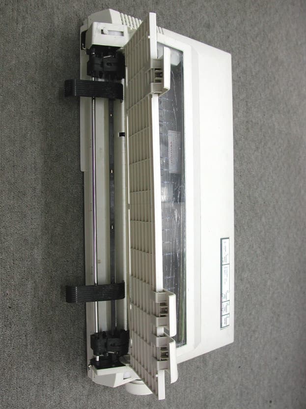
Click to zoom
Application Details
- Equipment Class
- JBP - Part 15 Class B Computing Device Peripheral
- Date of Grant
- Oct 29, 2001
- Application Purpose
- Original Equipment
- Date of Application
- Oct 29, 2001
- Equipment Note
- Printer
- Company
- TVS Electronics Limited
- Country
- India
Documents & Files
Document Text
Text extracted from the exhibit documents filed with the FCC. Open a document above to read the original.
Users Manual
Federal Communications Commission (FCC) Requirements, Part 15 This equipment has been tested and found to comply with the limits for a class B digital device, pursuant to part 15 of the FCC Rules. These limits are designed to provide reasonable protection against harmful interference in a residential installation. This equipment generates, uses and can radiate radio frequency energy and, if not installed and used in accordance with the instructions, may cause harmful interference to radio communications. However, there is no guarantee that interference will not occur in a particular installation. If this equipment does cause harmful interference to radio or television reception, which can be determined by turning the equipment off and on, the user is encouraged to try to correct the interference by one or more of the following measures: ---Reorient or relocate the receiving antenna. ---Increase the separation between the equipment and receiver. ---Connect the equipment into an outlet on a circuit different from that to which the receiver is connected. ---Consult the dealer or an experienced radio/TV technician for help. CAUTION: Any changes of modifications not expressly approved by the grantee of this device could void the users authority to operate the equipment.
ID Label/Location Info
LABEL Format: This device complies with Part 15 of the FCC Rules Operation is subject to the following two conditions: (1) This device may not cause harmful interference, and (2) This device must accept any interference received, including interference that may cause undesired operation Model No.:MSP245 FCC ID:OSCMSP-245 LABEL Size: 100 x 20 mm LABEL Position: LABEL
Test Report
Test Report ------------------------------------------------------------------------------- 2/16 Report No.: T5415396 Training Research Co., Ltd., TEL: 886-2-26935155, Fax: 886-2-26934440 Contents CHAPTER 1 INTRODUCTION......................................................................3 Description of EUT.......................................................................................3 Connections of EUT.....................................................................................3 Test method..................................................................................................3 Configuration of Test Setup..........................................................................4 Connections..................................................................................................5 List of Support Equipment............................................................................6 CHAPTER 2 CONDUCTED EMISSION TEST..................................................8 Test condition and setup...............................................................................8 List of test Instrument...................................................................................8 Conducted Test Placement: (Photographs)...................................................9 CHAPTER 3 RADIATED EMISSION TEST...................................................10 Test condition and setup.............................................................................10 List of test Instrument.................................................................................11 Radiated Test Placement: (Photographs)....................................................12 APPENDIX A..............................................................................................13 Conducted Emission Test Result................................................................13 APPENDIX B..............................................................................................14 Radiated Emission Test Result (Horizontal)..............................................14 Radiated Emission Test Result (Vertical)...................................................15 APPENDIX C..............................................................................................16 List of Modifications..................................................................................16 Test Report ------------------------------------------------------------------------------- 3/16 Report No.: T5415396 Training Research Co., Ltd., TEL: 886-2-26935155, Fax: 886-2-26934440 Chapter 1 Introduction Description of EUT This device is printing data equipment. It is designed to connect with a compatible computer via parallel interface. Connections of EUT (1) The power port of EUT is connected with the AC power source via a power cable. (2) The parallel port of EUT is connected with the parallel port of personal computer. Test method Pretest was found that the emission of operating mode is worse than standby mode. So, The final test is made at the operating mode. During testing, the EUT was operated at printing mode continuously. The test placement as the photographs showed is the worst case emission placed. (If the emission is close to the ambient, the resolution BW and view resolution will be reduced and the data will be recorded by detection of maximum hold peak mode.) The testing configuration of test setup is showing in the next page. Test Report ------------------------------------------------------------------------------- 4/16 Report No.: T5415396 Training Research Co., Ltd., TEL: 886-2-26935155, Fax: 886-2-26934440 Configuration of Test Setup USB Mouse USB Joystick Mouse Keyboard Monitor Modem EUT (Printer) PC Power Test Report ------------------------------------------------------------------------------- 5/16 Report No.: T5415396 Training Research Co., Ltd., TEL: 886-2-26935155, Fax: 886-2-26934440 Connections PC: *Serial Port --- an external modem *Printer Port --- EUT *Monitor Port --- a monitor *Keyboard Port --- a keyboard *Mouse Port --- a mouse *USB A Port --- a USB mouse *USB B Port --- a USB joystick (Each port on PC is connected with suitable device) EUT: *Power cable x 1 --- 223cm long, non-shielded, no ferrite core *Data Cable x 1 --- 142cm long, shielded, no ferrite core Test Report ------------------------------------------------------------------------------- 6/16 Report No.: T5415396 Training Research Co., Ltd., TEL: 886-2-26935155, Fax: 886-2-26934440 List of Support Equipment Conducted (Radiated) test: PC:HP Brio 8410 6/350 Model No.:D6928A Serial No. :TW90400174 FCC ID:N/A (Doc Approved) :3872H013 Power type:100 ~ 230VAC / 50 ~ 60Hz, 5A, Switching Power cord :Non-shielded, 2.30m long, Plastic, No ferrite core Monitor :ACER 15’ Color Display Model No.:1555 Serial No.:917160230583601429P5C431 FCC ID:JVP7254E :4872A030 Power type:110 ~ 240 VAC / 50 ~ 60 Hz, Switching Power cord:Shielded, 1.80m long, No ferrite core Data cable :Shielded, 1.34m long, with ferrite core Keyboard:HP Model No.:SK-2501K Serial No.:M981216213 FCC ID:GYUR38SK :3862A621 Power type:By PC Data cable :Shielded, 1.70m long, with ferrite core Test Report ------------------------------------------------------------------------------- 7/16 Report No.: T5415396 Training Research Co., Ltd., TEL: 886-2-26935155, Fax: 886-2-26934440 Mouse:HP Model No.:M-S34 Serial No.:LZC84446151 FCC ID:DZL211029 :4862A011 Power type:By PC Power cord:Non-shielded, 1.80m long, No ferrite core Modem:ACEEX Model No.:XDM-56V14 FCC ID:IFAXDM-56V14 Power type:Linear Power cord:Non-shielded, 1.9m long, No ferrite cord Data cable :RS232, Shielded, 1.2m long, No ferrite core RJ11C x 2, 7’ long non-shielded, No ferrite core USB Mouse:Logitech Model No.:M-BA47 Serial No.:LZE92250027 FCC ID:N/A, Doc Approved :4872A220 Power type:Powered by PC Power Cable:Shielded, 1.5m long, Plastic hoods, No ferrite bead USB Joystick:Padix Model No.:QF-305U Seria…
Text truncated - open the document above for the full version.
Test Setup Photos
Test Report ------------------------------------------------------------------------------- 9/16 Report No.: T5415396 Training Research Co., Ltd., TEL: 886-2-26935155, Fax: 886-2-26934440 Conducted Test Placement: (Photographs) Test Report ------------------------------------------------------------------------------- 12/16 Report No.: T5415396 Training Research Co., Ltd., TEL: 886-2-26935155, Fax: 886-2-26934440 Radiated Test Placement: (Photographs)
Contact Information
Applicant
K. Kannan(Vice-President-SPG)
Test Firm
Training Research Co., Ltd.Jack Tsai
Technical Specifications
| # | Rule Parts | Frequency Range | Power Output |
|---|---|---|---|
| 1 | 15B | - | - |
Other Applications from TVS Electronics Limited
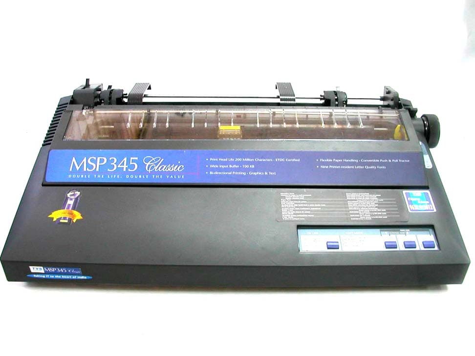
OSCMSP345CLASSIC
Oct 29, 2003PRINTER
Equipment Class
JBP - Part 15 Class B Computing Device Peripheral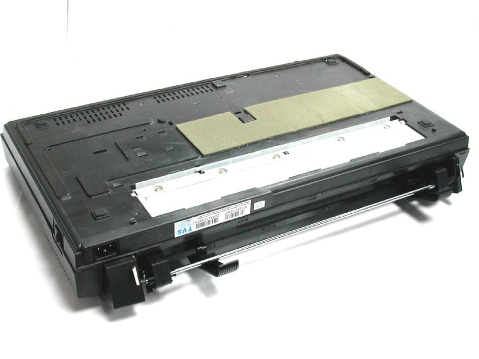
OSCMSP355XLC
Oct 29, 2003PRINTER
Equipment Class
JBP - Part 15 Class B Computing Device Peripheral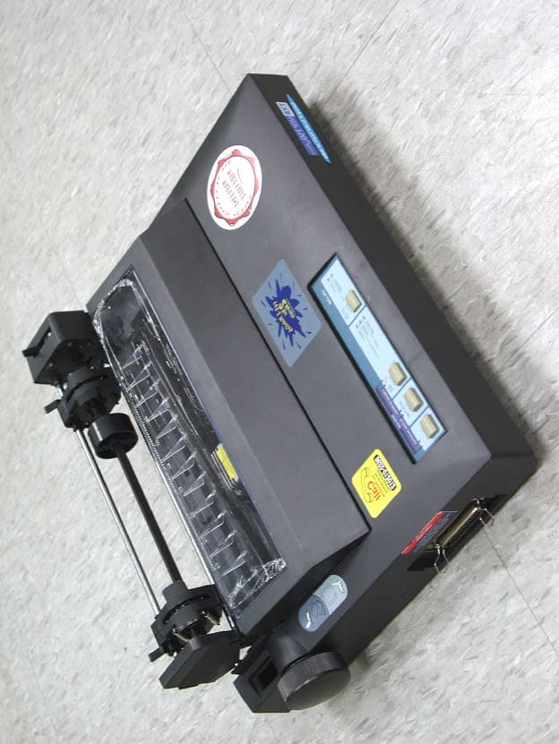
OSCMSP250
Apr 13, 2003Printer
Equipment Class
JBP - Part 15 Class B Computing Device Peripheral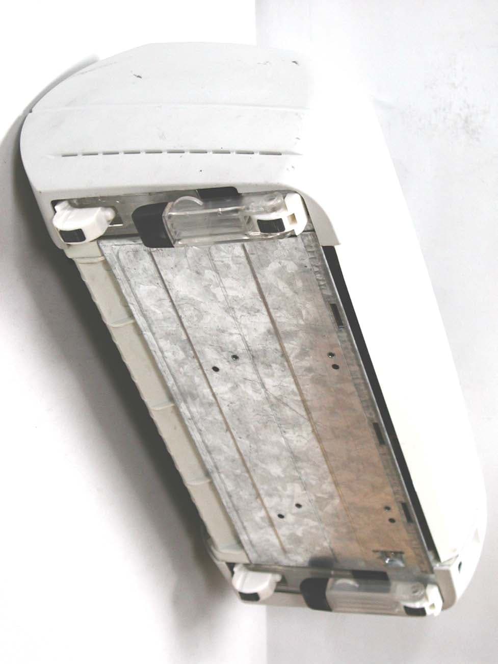
OSCPROTON
Jul 28, 2002Printer
Equipment Class
JBP - Part 15 Class B Computing Device Peripheral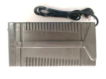
OSCSU-CLASSIC500
Dec 04, 2001Uninterruptible Power Supply
Equipment Class
JBP - Part 15 Class B Computing Device Peripheral