OSCMSP250Printer
TVS Electronics Limited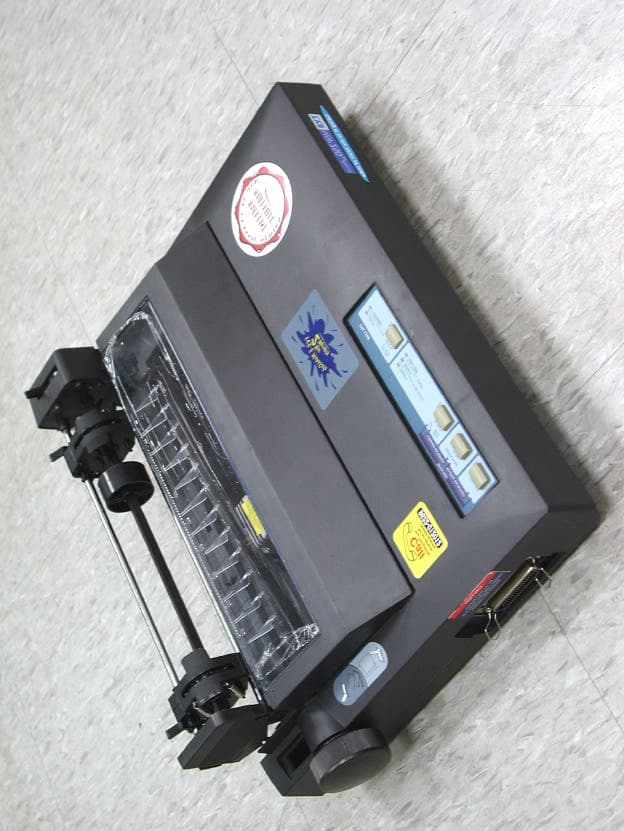
Click to zoom
Application Details
- Equipment Class
- JBP - Part 15 Class B Computing Device Peripheral
- Date of Grant
- Apr 13, 2003
- Application Purpose
- Original Equipment
- Date of Application
- Apr 13, 2003
- Equipment Note
- Printer
- Company
- TVS Electronics Limited
- Country
- India
Documents & Files
Document Text
Text extracted from the exhibit documents filed with the FCC. Open a document above to read the original.
Users Manual
FORWARD MICROFEEDREVERSE MICROFEED PAPER PARK MENU MODE COPY MODE Single Sheet Insertion 6 6 Selecting and Loading paper Paper Select Lever for Continuous feed Installing the Printer Ribbon 1 1 Installing your Printer Power Switch Location Connection Parallel Interface Cable Components in your printer 2 2 3 3 4 4 Paper Insertion Bottom Feed (Pull Tractor Option) 8 8 Printing Continuous Paper with Tractor Unit in Pull Position 7 7 Tractor Select Lever 5 5 Printing in Single Sheets 9 9 10 10 Control Panel MSP 9 wire printer Operating the control panel ONLINE light glows, the printer is in Normal Operation Mode. OFFLINE will pause printing. LF moves one line forward. FF moves one page forward. FONT to select a style of the character. PITCH to select the size of the character MSP 24 wire printer Operating the control panel ONLINE light glows, the printer is in Normal Operation Mode. OFFLINE will pause printing. LF moves one line forward. FF moves one page forward. FONT to select a style of the character. PITCH to select the size of the character Mail back your warranty registration card today Select Lever Printing Continuous Stationery in Push Tractor Mode Select Lever Insertion Platen Parallel Interface Inserting Continuous Paper in Push Tractor Helpful Hints • Use Normal Density MSP Ribbons for 9 wire Printers. Use of improper ribbon may damage the print head and invalidate the warranty. • Use only High Density MSP Ribbons for 24 wire Printers. Use of improper ribbon may damage the print head and invalidate the warranty. • If you are replacing a ribbon be sure the printer of OFF and the print head has cooled. • Carefully read the instructions for correct ribbon placements. Improper placement can cause smudged printing and may jam the ribbon. • ONLINE is the printer's normal operating mode. When the printer is ONLINE, it can receive data from your computer and print. When the printer is OFFLINE, it stops printing and responds only to control-panel instructions, such as moving the paper. • To completely cancel the print job, first cancel the job in your software application. Then clear the data from the printer buffer. • Because of advanced paper-handling features it is seldom necessary to turn the paper feed knob. More frequently turning the paper feed knob causes misalingment. Use the Control panel instead. • Paper tear off, top-of-form adjustment and paper parking are not available when using tractor in PULL mode. • Do not rotate the PLATEN KNOB when the printer is in power ON condion. • The top margin is usually set by your software. You may not need to change the top-of- form setting very often. • For serial interface connection you need to install an optional serial interface board. Please contact your nearest TVS-E dealer. Serial interface cable comes with a board. • If the printer is used heavily or in a dusty environment consult TVS-E service centre for advice on periodic cleaning and lubrication. www.tvs-e.com Quick Reference Guide Federal Communications Commission (FCC) Requirements, Part 15 This equipment has been tested and found to comply with the limits for a class B digital device, pursuant to part 15 of the FCC Rules. These limits are designed to provide reasonable protection against harmful interference in a residential installation. This equipment generates, uses and can radiate radio frequency energy and, if not installed and used in accordance with the instructions, may cause harmful interference to radio communications. However, there is no guarantee that interference will not occur in a particular installation. If this equipment does cause harmful interference to radio or television reception, which can be determined by turning the equipment off and on, the user is encouraged to try to correct the interference by one or more of the following measures: ---Reorient or relocate the receiving antenna. ---Increase the separation between the equipment and receiver. ---Connect the equipment into an outlet on a circuit different from that to which the receiver is connected. ---Consult the dealer or an experienced radio/TV technician for help. NOTE THIS MANUFACTURER IS NOT RESPONSIBLE FOR ANY RADIO OR TV INTERFERENCE CAUSED BY UNAUTHORIZED MODIFICATIONS TO THIS EQUIPMENT. SUCH MODIFICATIONS COULD VOID THE USER'S AUTHORITY TO OPERATE THE EQUIPMENT.
Block Diagram
MSP 250 XLC PRINTER BLOCK DIAGRAM Main board Main Gate ArrayCPU AC power Input ( 150 - 270 Vac) 47- 63 Hz Not generated through Oscillator or Crystal. Connected to the CLK signal of the CPU 25 Mhz Sensors ( Paper End & Home Sense ) Carriage Feed Motor Print Head ( With thermistor ) Paper Feed Motor 6.25 Mhz PSU Inlet Sub assy Operation Panel Serial Interface ( Optional ) Parallel Interface ( Host) 30V,GND,5V
ID Label/Location Info
LABEL Format: This device complies with Part 15 of the FCC Rules Operation is subject to the following two conditions: (1) This device may not cause harmful interference, and (2) This device must accept any interference received, including interference that may cause undesired operation Model No. : MSP 250 FCC ID : OSCMSP250 LABEL Size: 100 x 20 mm LABEL Position:
Schematics
5 5 4 4 3 3 2 2 1 1 DD CC BB AA 0.01UF0.01UF0.01UF0.01UF 0.01UF0.01UF0.01UF DECOUPLING CAPACITORS DECAPS FOR GATE ARRAY (ADDED EXTRA) ADD THIS DECAP NEAT MOUNTING HOLE 2 VCC VCCVCCVCC VCC C16 0.01UF DC33DC32 DC30 DC29 DC31 1 0 4 D C 4 0 DC34 DC1 0.01UF DC4 0.01UF DC3 0.01UF DC2 0.01UF C20 0.01UF DC12 0.01UF DC11 0.01UF DC10 0.01UF DC9 0.01UF DC8 0.01UF DC7 0.01UF DC6 0.01UF DC5 0.01UF DC15 0.01UF DC14 0.01UF DC13 1 0 4 D C 1 7 1 0 4 D C 4 1 1 0 4 D C 3 9 PDF created with FinePrint pdfFactory trial version http://www.fineprint.com 5 5 4 4 3 3 2 2 1 1 DD CC BB AA DC27 DC28 DC35 DC20 1000PF DC21 DC22 4.7K PARALLEL INTERFACE (VCC) LTXD LRXD LRTS LDSR PESW2 LDTR FAULT# PRIME# SLCT_IN# DATA1 STROBE# DATA2 DATA4 ACKNLG# DATA3 BUSY DATA7 DATA5 SLCT DATA8 PE ATFD_XT# DATA6 SCNT HPWD VCC 40V 5V 25V 5V 5V R473.3K J6 1 2 3 4 5 6 7 8 9 10 11 12 13 14 1000pF R56 C150.01uF J7 POWER CON 6 5 4 3 2 1 U18A 74HC123 14 15 1 2 3 13 4 16 CEXT REXT/CEXT A B CLR Q Q VCC 470pF 1000pF 1000pF 1000pF D C 1 8 D C 1 9 J5 CON36 1 2 3 4 5 6 7 8 9 10 11 12 13 14 15 16 17 18 19 20 21 22 23 24 25 26 27 28 29 30 31 32 33 34 35 36 PDF created with FinePrint pdfFactory trial version http://www.fineprint.com 5 5 4 4 3 3 2 2 1 1 DD CC BB AA [ ORIGINAL PAPER SENSOR ] SENSORS PESW1 HPSW U8-22 STROBE# 5 V 5V R45 3.3K R43 3.3K J3 1 2 3 J4 CON2 1 2 RN15 4R8P 3.3K 1 2 3 45 6 7 8 R44 150E D C 3 7 D C 3 8 PDF created with FinePrint pdfFactory trial version http://www.fineprint.com 5 5 4 4 3 3 2 2 1 1 DD CC BB AA 9K1 CARRAIGE MOTOR DRIVER R73 3K3 3K3 0.91E 2W Q8 3K3 R71 Q9 RN19 RN20 R70 R69 R64 R72 3K3 3K3 R68 TRA4 200E 0.91E 2W 4K7 R60 1K2R63 R67 US1G200 CRMB# CRMD# CRMA# CVH1# CVH2# CVH3# CRMC# USIG200 25V 5V 1 2 3 45 6 7 8 J2 6 5 4 3 2 1 1234 5678 104 DC23 Q10 TP11 1 TP12 1 TP16 1 TP13 1 2K4 SLA 7032M 6 5 17 16 4 15 7 1 8 11 18 931 4 1 0 21 3 12 INA INA INB INB GA GB VSA OUT A OUT A OUT B OUT B R S A R C T A R C T B R S B T D A T D B VSB PDF created with FinePrint pdfFactory trial version http://www.fineprint.com 5 5 4 4 3 3 2 2 1 1 DD CC BB AA DRAFT FONT ROMAN FONT SAN SERIF FONT 10CPI CONDENSED ONLINE LED 3K3 OPERATION PANEL FONT1LED FONT2LED FONT3LED PITCH2LED ONLINELED JP4_4 JP4_2 JP4_5 JP4_3 PITCHSW ONLINESW FONTSW LF\FFSW PITCH1LED JP4_3 JP4_2 JP4_5 JP4_4 5V RN1 1 2 3 45 6 7 8 JP4 12 HEADER 1 2 3 4 5 6 7 8 9 10 11 12 U10B 74HC04 34 U10F 74HC04 1312 U10C 74HC04 56 U10D 74HC04 98 U10A 74HC04 12 U10E 74HC04 1110 PDF created with FinePrint pdfFactory trial version http://www.fineprint.com 5 5 4 4 3 3 2 2 1 1 DD CC BB AA 3K3 3K3 3K3 3K3 TEST_POINTS GATE ARRAY STROBE# PRIME# D1 D2 D7 D0 D6 D3 D4 D5 DSTRB# D0 D1 D2 D3 D4 D5 D6 D7 E # C L K A 3 R W # A L E A 2 A 1 A 0 A 1 5 P E S W 1 STROBE# PRIME# ATFD_XT# FAULT# SLCT P E ACKNLG# BUSY USIG101 USIG100 USIG102 USIG103 USIG104 SLCT_IN# DATA2 DATA1 DATA5 DATA4 DATA3 DATA6 DATA8 DATA7 FAULT# SLCT_IN# SLCT DATA2 DATA4 DATA3 ATFD_XT# H P W D R E S E T # C R C L K DATA1 DATA5 DATA7 DATA8 DATA6 PE BUSY ACKNLG# PRIME# CRCLK E# RW# CLK ICCDCS RD# ALE U8-22 PHD3 U S I G 1 0 4 P F M B P F M D C R M B # L D S R U S I G 1 0 3 PHD9 PHD5 A B 1 8 U S I G 1 0 1 P H D 2 W R # C R M D # R A M C S 1 # R D # DSTRB# R A M C S 2 # PHD7 A B 1 7 P R O M C S # PHD6 U S I G 1 0 2 R D Y # H P S W A B 1 6 PHD8 PHD4 U S I G 1 0 0 C R M A # P H D 1 I C C D C S P F M C C R M C # P F M A RAMCS1# HPWD PROMCS# 5V 5V 5V TP10 1 RN9 1 2 3 4 5 6 7 8 9 10 RN8 1 2 3 4 5 6 7 8 9 10 R7100E U7D 74HC06 98 R81K R17 1KR181K U7E 74HC06 1110 U7F 74HC06 1312 U8 M65135FP 82 74 75 76 77 79 80 81 90 65 40 15 3 28 53 78 9 6 9 7 9 8 9 9 1 0 0 4 8 4 9 5 0 5 1 5 2 5 4 5 5 5 6 7 0 7 1 7 2 7 3 8 3 8 4 8 5 9 5 4 5 4 6 4 7 3 2 3 3 3 4 3 5 5 7 5 8 5 9 6 0 6 6 3 6 9 1 8 6 37 41 67 61 92 62 93 38 87 42 63 68 39 69 43 88 44 94 89 64 121 9 2 0 2 5 2 6 2 7 2 9 3 0 3 1 1 2 1 3 1 4 1 8 2 1 2 2 2 3 1 7 2 4 1 6 4567891 0 1 1 D7 D0 D1 D2 D3 D4 D5 D6 VSS4 VSS3 VSS2 VSS1 VDD1 VDD2 VDD3 VDD4 B U S Y A C K N W P E S L C T F A U L T A B 1 6 A B 1 7 A B 1 8 A B 1 9 A B 2 0 A B 2 1 A B 2 2 A B 2 3 P R O M C S C G R O M C S R A M C S 1 R M M C S 2 E X C S 1 E X C S 2 I C C D C S L C D C S R D W R R O Y P F M A P F M B P F M C P F M D C R M A C R M B C R M C C R M D H P D 1 H P D 2 H P D 3 H P D 4 HPD5 HPD6 HPD7 HPD8 HPD9 HPD10 HPD11 HPD12 HPD13 HPD14 HPD15 HPD16 HPD17 HPD18 HPD19 HPD20 HPD21 HPD22 HPD23 HPD24 S T R O B E P R I M E A T F D _ X 1 S L C T _ I N D S R A 0 A 1 A 2 A 3 A 1 5 ER / W C L K A L E P E S W S L C T S W H P S W C R C L K H P W D R E S E T D A T A 1 D A T A 2 D A T A 3 D A T A 4 D A T A 5 D A T A 6 D A T A 7 D A T A 8 R193K3 R20 3K3 U7B 74HC06 34 U7A 74HC06 12 RN11 1234 5678 TP9 1 TP5 1 C8 1000PF C9 1000PF RN10 1234 5678 TP1 1 TP2 1 TP4 1 TP3 1 TP6 1 TP8 1 TP7 1 PDF created with FinePrint pdfFactory trial version http://www.fineprint.com 5 5 4 4 3 3 2 2 1 1 DD CC BB AA SHORT JP7 & JP 10 FOR EPROM SHORT JP8 & JP9 FOR FLASH NOTE: MEMORY INTERFACING A0 A1 A2 A3 A4 A5 A6 A7 A8 A9 A10 A13 A12 A11 A15 A14 WR# AB16 RD# D0 D1 D2 D3 D4 D5 D6 D7 D0 D1 D2 D3 D7 D4 D6 D5 A0 A1 A2 A3 A4 A5 A6 A7 A8 A9 A10 A13 A12 A11 A15 A14 AB16 AB17 RD#AB18 AB18 SCLK EEPOK3 A0 A1 A2 A3 A4 A5 A6 A7 A8 A9 A10 A11 A12 A13 A14 A15 RAMCS1# RAMCS2# D0 D1 D2 D3 D4 D5 D6 D7 D0 D1 D2 D3 D4 D5 D6 D7 A0 A1 A2 A3 A4 A5 A6 A7 A8 A9 A10 A11 A12 A13 A14 A15 AB16 AB17 AB18 AB18 PROMCS# RD# SCLK RD# AB16 EEPOK3 ICCDCS WR# WR# 5V 5V 5V 5V 5V JP8 12 12 JP10 12 12 U16A 74LS08 1 2 3 U6 24C02A 1 2 3 45 6 7 8 A0 A1 A2 VSSSDA SCL NF VCC U4 27C4001 13 14 15 17 18 19 20 21 12 11 10 9 8 7 6 5 27 26 23 25 4 28 29 3 1 22 24 2 30 31 3 2 1 6 O0 O1 O2 O3 O4 O5 O6 O7 A0 A1 A2 A3 A4 A5 A6 A7 A8 A9 A10 A11 A12 A13 A14 A15 VPP CE OE A16 A17 PGM V C C G N D U3 UM621024B 13 14 15 17 18 19 20 21 12 11 10 9 8 7 6 5 27 26 23 25 4 28 3 31 22 24 29 2 30 3 2 1 6 O0 O1 O2 O3 O4 O5 O6 O7 A0 A1 A2 A3 A4 A5 A6 A7 A8 A9 A10 A11 A12 A13 A14 A15 CE1 OE WE A16 CE2 V C C G N D U16B 74LS08 4 5 6 JP9 12 12 JP7 12 12 PDF created with FinePrint pdfFactory trial version http://www.fineprint.com 5 5 4 4 3 3 2 2 1 1 DD CC BB AA 1M …
Text truncated - open the document above for the full version.
Test Report
Test Report ------------------------------------------------------------------------------- 1/12 Report No.: T5415475 Training Research Co., Ltd., TEL: 886-2-26935155, Fax: 886-2-26934440 Report No. T5415475 Specifications FCC Part 15.109(g), CISPR 22, Class B Test Method ANSI C63.4 1992 Applicant TVS ELECTRONICS LTD. Applicant Plot No.34, Developed Plots, South Phase Industrial Estate, address Guindy, Chennai, Tamilnadu, India 600 032 Items tested Printer Model No. MSP250 (Sample # T54474) Results Compliance (As detailed within this report) Date 06/19/2002 (month / day / year) (Sample received) 08/23/2002 (month / day / year) (Test) Prepared by Project Engineer Authorized by General Manager (Frank Tsai) Issue date March 24, 2003 (month / day / year) Modifications Appendix C Tested by Training Research Co., Ltd. Office at 1F, No. 255, Nan Yang Street, Hsichih, Taipei Hsien 221, Taiwan Open site at No. 5-3, Lane 21, Yen Chiu Yuan Rd., Sec. 4, Taipei, Taiwan Conditions of issue : (1) This test report shall not be reproduced except in full, without written approval of TRC. And the test result contained within this report only relate to the sample submitted for testing. (2) This report must not be used by the client to claim product endorsement by NVLAP or any agency of U.S. Government. NVLAP LAB CODE: 200174-0 FCC ID:OSCMSP250 Test Report ------------------------------------------------------------------------------- 2/12 Report No.: T5415475 Training Research Co., Ltd., TEL: 886-2-26935155, Fax: 886-2-26934440 Contents CHAPTER 1 INTRODUCTION.......................................................................3 Description of EUT......................................................................................3 Connections of EUT.....................................................................................3 Test method..................................................................................................3 Configuration of Test Setup.........................................................................4 Connections of Equipment...........................................................................4 List of Support Equipment...........................................................................5 CHAPTER 2 CONDUCTED EMISSION TEST...................................................7 Test condition and setup...............................................................................7 List of test Instrument...................................................................................7 CHAPTER 3 RADIATED EMISSION TEST......................................................8 Test condition and setup...............................................................................8 List of test Instrument...................................................................................8 APPENDIX A................................................................................................9 Conducted Emission Test Result..................................................................9 APPENDIX B..............................................................................................10 Radiated Emission Test Result (Polarity-horizontal).................................10 Radiated Emission Test Result (Polarity-vertical).....................................11 APPENDIX C..............................................................................................12 Modification List........................................................................................12 Test Report ------------------------------------------------------------------------------- 3/12 Report No.: T5415475 Training Research Co., Ltd., TEL: 886-2-26935155, Fax: 886-2-26934440 Chapter 1 Introduction Description of EUT This device is printing data equipment. It is designed to connect with a compatible computer via parallel interface. Connections of EUT (1)The power port is connected with a power cable to AC power source. (2)The parallel port is connected with the printer-port of personal computer. Test method Pretest was found that the emission of operating mode is worse than standby mode. So, The final test is made at the operating mode. During testing, the EUT was operated at printing mode continuously. The test placement as the photographs showed is the worst case emission placed. (If the emission is close to the ambient, the resolution BW and view resolution will be reduced and the data will be recorded by detection of maximum hold peak mode.) The testing configuration of test setup is showing in the next page. Test Report ------------------------------------------------------------------------------- 4/12 Report No.: T5415475 Training Research Co., Ltd., TEL: 886-2-26935155, Fax: 886-2-26934440 Configuration of Test Setup Connections of Equipment PC: *Serial Port --- an external modem *Printer Port --- EUT *Monitor Port --- a monitor *Keyboard Port --- a PS2 keyboard *Mouse Port --- a PS2 mouse *USB A Port --- a USB mouse *USB B Port --- a USB gamepad (Each port on PC is connected with suitable device) EUT: *Power cable x 1 --- 186cm long, plastic, non-shielded, no ferrite core *Data cable x 1 --- 136cm long, shielded, no ferrite core USB Mouse PS2 Mouse PS2 Keyboard Monitor PC Power Source Modem EUT (Printer) Data Cable Power Cable USB Game pad Test Report ------------------------------------------------------------------------------- 5/12 Report No.: T5415475 Training Research Co., Ltd., TEL: 886-2-26935155, Fax: 886-2-26934440 List of Support Equipment Conducted (Radiated) test: PC : HP Brio 85xx 6/350 Model No. : D6928A Serial No. : SG91801552 FCC ID : N/A, DoC (Declaration of Confirmation) Approved : 3872H013 Power type : 100 ~ 230VAC / 50 ~ 60Hz, 5A, Switching Power cord : Non-shielded, 2.33m long, Plastic, No ferrite core Monitor : HP 15’ Color Monitor Model No. : D2827A Serial No. : KR91379759 FCC ID : C5F7NFCMC1518X : 3872B039 Power type : 110 ~ 240 VAC / 50 ~ 60 …
Text truncated - open the document above for the full version.
Test Setup Photos
Test Setup Photos ------------------------------------------------------------------------- 1/2 FCC ID: OSCMSP250 Training Research Co., Ltd., TEL: 886-2-26935155, Fax: 886-2-26934440 Conducted Test Setup Placement: (Photographs) Test Setup Photos ------------------------------------------------------------------------- 2/2 FCC ID: OSCMSP250 Training Research Co., Ltd., TEL: 886-2-26935155, Fax: 886-2-26934440 Radiated Test Setup Placement: (Photographs)
Contact Information
Applicant
K. Kannan(Vice-President-SPG)
Test Firm
Training Research Co., Ltd.Jack Tsai
Technical Specifications
| # | Rule Parts | Frequency Range | Power Output |
|---|---|---|---|
| 1 | 15B | - | - |
Other Applications from TVS Electronics Limited
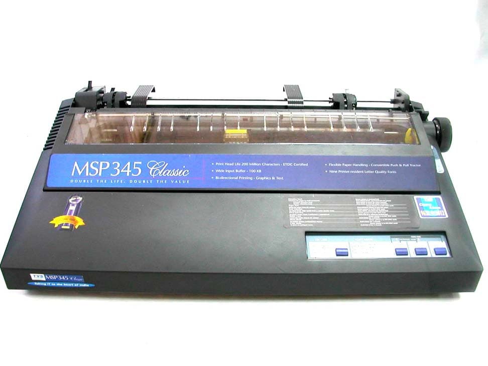
OSCMSP345CLASSIC
Oct 29, 2003PRINTER
Equipment Class
JBP - Part 15 Class B Computing Device Peripheral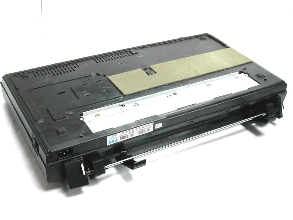
OSCMSP355XLC
Oct 29, 2003PRINTER
Equipment Class
JBP - Part 15 Class B Computing Device Peripheral
OSCPROTON
Jul 28, 2002Printer
Equipment Class
JBP - Part 15 Class B Computing Device Peripheral
OSCSU-CLASSIC500
Dec 04, 2001Uninterruptible Power Supply
Equipment Class
JBP - Part 15 Class B Computing Device Peripheral
OSCMSP-245
Oct 29, 2001Printer
Equipment Class
JBP - Part 15 Class B Computing Device Peripheral