OSCSU-CLASSIC500Uninterruptible Power Supply
TVS Electronics Limited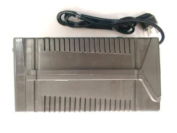
Click to zoom
Application Details
- Equipment Class
- JBP - Part 15 Class B Computing Device Peripheral
- Date of Grant
- Dec 04, 2001
- Application Purpose
- Original Equipment
- Date of Application
- Dec 04, 2001
- Equipment Note
- Uninterruptible Power Supply
- Company
- TVS Electronics Limited
- Country
- India
Documents & Files
Document Text
Text extracted from the exhibit documents filed with the FCC. Open a document above to read the original.
Users Manual
EXHIBIT C User Manual User Manual Power UPS 500 Page 1 USER MANUAL STARTUPS LITE 500 REV 1.0 UNINTERRUPTIBLE POWER SUPPLY User Manual Power UPS 500 Page 2 User Manual Power UPS 500 Dear Customer, Congratulations on having made an intelligent choice. This product is designed and manufac- tured with utmost care to give you high quality trouble-free performance in the years to come. Please register your product by filling the enclosed Business Reply Card and Mailing it to us. This will enable you to avail free warranty services, in the unlikely requirement of any service assistance. This registration will also entitle you to receive free mailers on product upgrades, service cam- paigns, etc. in case you do not find the Business Reply Card in this manual, please write to us for a new registration card: Customer support, TVS Electronics Limited, No. 34, Developed plots, South Phase, Industrial Estate, Guindy, Chennai 600 032. Please note that it is mandatory to register your product with us. The warranty applicable for this product is likely to be rejected in case of non-registration of your product with us. For any queries on our product and/or services you can contact either our branch office or our authorised service provider. List of service providers are available in this CD. For any on-line support, please contact your nearest call center, an exclusive Tele-solution desk available for all TVS-E customers. The contact details are: E-Mail: careline @esa.tvse.co.in Carecentre-Chennai:9622012012 Carecentre-Bangalore:6565010/6561679 Carecentre-Mumbai:7905717/7668496 Carefax (Fax on demand):+91-44-2327588 Website:www.tvse.com OR TVS Electronics Limited. No.35:Developed plots, South phase Guindy industrial Estate Guindy Chennai - 600 032. User Manual Power UPS 500 Page 3 TVS ELECTRONICS LIMITED HARDWARE WARRANTY What the warranty covers TVS Electronics Limited, warrants the buyer, that its hardware product sold is free from defec- tive workmanship or material under normal use and service. If a product proves to be defective in material or workmanship during the warranty period, we will at our sole option repair or replace the product with a like product. How long is the warranty Power UPS 500 is warranted for 3 years without battery for all manufacturing defects. The battery is warranted for 1 year. During the warranty TVSE will repair or replace the unit and return to the Dealer/Distributor/Customer. Whom the Warranty protects This warranty is only valid for the first consumer/purchaser. What the warranty does not cover: 1. Any product on which the serial number has been defaced, modified or removed. 2. Damage, deterioration or malfunction resulting from: a) Accident, misuse, neglect, fire, water, lightning or other acts of nature. Unauthorised product modification or failure to follow instruction supplied with the product. b) Repair or attempted repair by anyone not authorised by TVSE. c) Repair or attempted repair using components not specified/recommended. d) Damage due to unauthorised shipment. e) Removal or installation of the product by unauthorised personnel. f) Operation not maintained with TVSE specification. g) Causes external to the product, such as electric power fluctuation or failure, improper earthing. h) Use of suppliers or products not meeting our specification. i) Normal wear and tear due to usage. j) Any other cause that does not relate to product defects. 3. Reinstallation and Preparation of site for installing the UPS. User Manual Power UPS 500 Page 4 User Manual Power UPS We thank you for selecting a TVSE Uninterruptible Power Supply (UPS) and recommend that you read these instructions carefully before installation and start-up of the Power UPS 500. Please keep this manual in a safe place for future reference. Contents 1.Introduction....................................................................... 6 2.Safety ................................................................................ 7 3.Outlook And Function ........................................................ 8 4.Installation....................................................................... 11 5.Operation ........................................................................ 12 6.Alarms............................................................................. 13 7.Specifications ........................................................14 8.On-Battery Run Time Table ............................................. 15 9.Troubleshooting............................................................... 16 10. About The Battery ........................................................... 17 11. Storage.......................................................................18 12. Communications Port....................................................18 13. Frequently asked questions...........................................19 13. How to get service........................................................20 User Manual Power UPS 500 Page 5 1Introduction The Power UPS will help you to protect your sensitive equipment like computers and telecommunication installations against malfunctioning due to non-reliable or distorted mains/ utility/line - voltage This modern, microprocessor controlled UPS protects the connected equipment against Surges, Sags, Spikes, etc. by means of an internal filter that works all the time. During electrical power failures, the unit employs its internal maintenance-free battery to supply back-up power without any interruption. The UPS is equipped with many features that will make your equipment to operate more reliable. The packing kit contains UPS Power UPS 500VA, Output power cable and CD-ROM. Built-in-Automatic Voltage Regulator: Provides regulated output voltage even under worst power conditions. Wide Input voltage range : Minimises calls on battery. Prolongs battery life. No load shutdown: Avoids unnecessary draining of batteries and increases the battery life. User friendly output s…
Text truncated - open the document above for the full version.
Block Diagram
EXHIBIT E Block Diagram
ID Label/Location Info
List of Exhibit EXHIBIT A Sample Label EXHIBIT B Test Report EXHIBIT C User Manual EXHIBIT D Circuit Diagram EXHIBIT E Block Diagram EXHIBIT F Photographs of EUT EXHIBIT A Sample Label LABEL Format: This device complies with Part 15 of the FCC Rules Operation is subject to the following two conditions: (1) This device may not cause harmful interference, and (2) This device must accept any interference received, including interference that may cause undesired operation. FCC ID : OSCSU-CLASSIC500 Model No.: SU-CLASSIC 500 LABEL Size: 45 X25 mm LABEL
Test Report
EXHIBIT B Test Report Test Report ---------------------------------------------------------------------------------------------------------- 2/15 Report No.: T5415462 Training Research Co., Ltd., TEL: 886-2-26461146, Fax: 886-2-26461778 Contents Chapter 1 Introduction Description of EUT ................................................................................................................ 3 Configuration of Test Setup .................................................................................................... 4 List of Support Equipment ...................................................................................................... 5 Chapter 2 Conducted Emission Test Test Condition and Setup ....................................................................................................... 7 Conducted Test Placement....................................................................................................... 8 Chapter 3 Radiated Emission Test Test Condition and Setup ....................................................................................................... 9 Radiated Test Placement ....................................................................................................... 10 Appendix A : Conducted test result.................................................................................................................11 Appendix B : Radiated test result....................................................................................................................15 Test Report ---------------------------------------------------------------------------------------------------------- 3/15 Report No.: T5415462 Training Research Co., Ltd., TEL: 886-2-26461146, Fax: 886-2-26461778 Chapter 1 Introduction Description of EUT: The EUT specifications: *Input frequency : 50 ±5 Hz *Input voltage window : 140-300V AC *Output frequency : 50Hz ± 0.1 Hz in battery mode *Output voltage mains mode : 190-255V *Output voltage inverter mode : 230V±5% output load variation of 0-100% *Wave form : Quasi sine wave *Transfer time : 4msec typical *Power factor : 0.6 *Battery type : Maintenance-free lead acid (12V-7Ah) *Recharge time : 8 hours typical from total discharge (UPS may be used immediately after discharge, but will Provide shorter backup time. *Temperature : -10 to 40 °C: operating -20 to 55 °C: transport/storage for limited time *Relative humidity : 0 to 95%, non-condensing Test method: Pretest was found that the emission of operating mode is worse than standby mode. So, The final test is made at the operating mode. During the pretest, the following modes were tested: 1. Charging mode: (a) at 50% power consumption. (b) at 100% power consumption. 2. Discharging mode: (a) at 50% power consumption. (b) at 100% power consumption. The test placement as the photographs showed is the worst case emission placed. And the worst case test data were recorded in the test report. (If the emission is close to the ambient, the resolution BW and view resolution will be reduced and the data will be recorded by detection of maximum hold peak mode.) The testing configuration of test setup is showing in the next page. Test Report ---------------------------------------------------------------------------------------------------------- 4/15 Report No.: T5415462 Training Research Co., Ltd., TEL: 886-2-26461146, Fax: 886-2-26461778 Configuration of test setup Connections: PC: *Serial Port --- via a 76cm shielded RS-232 cable to EUT. *Monitor Port --- a monitor with 1.5m length data cable. *Keyboard Port --- a keyboard with 1.7m length data cable. *Mouse Port --- a mouse with 1.8m long of data cable. *Printer port --- a printer with 1.80m length data cable. *USB Port A --- a joystick with 1.5m long, shielded and no ferrite bead data cable. *USB Port B --- a mouse with 1.8m long of data cable. (Each port on PC is connected with suitable device) EUT: *Power cable --- via a 1.60m long non-shielded, no ferrite bead power cable to the power source. *AC Jack 1 --- via a 1.85m long non-shielded, no ferrite bead power cable to the PC. *AC Jack 2~3--- via a 1.85m long non-shielded, no ferrite bead power cable that terminated. *AC Jack 4 --- via a 1.85m long non-shielded, no ferrite bead power cable to the Lights. *Serial Port --- via a 76cm shielded RS-232 cable to the PC. *LAN IN --- with a 1.5m long, non-shielded, no ferrite bead, RJ-45 cable that terminated. *LAN OUT --- with a 1.5m long, non-shielded, no ferrite bead, RJ-45 cable that terminated. Printer Power Source Mouse Keyboard Monitor PC EUT USB Joystick Mouse Lights Test Report ---------------------------------------------------------------------------------------------------------- 5/15 Report No.: T5415462 Training Research Co., Ltd., TEL: 886-2-26461146, Fax: 886-2-26461778 List of support equipment Conducted (Radiated) test: PC : HP Brio 8410 6/350 Model No. : D6928A Serial No. : TW90400174 FCC ID : Doc Approved Power type : 100 ~ 230VAC / 50 ~ 60Hz, 5A, Switching Power cord : Non-shielded, 2.30m long, Plastic, No ferrite core Monitor : ACER 15’ Color Display Model No. : 1555 Serial No. : 917160230583601429P5C431 FCC ID : JVP7254E Power type : Switching Power cord : Shielded, 1.80m long, No ferrite core Data cable : Shielded, 1.34m long, with ferrite core Keyboard : HP Model No. : SK-2501K Serial No. : M981216213 FCC ID : GYUR38SK Power type : By PC Data cable : Shielded, 1.70m long, with ferrite core Mouse : HP Model No. : M-S34 Serial No. : LZC84446151 FCC ID : DZL211029 Power type : By PC Power cord : Non-shielded, 1.80m long, No ferrite core Test Report ---------------------------------------------------------------------------------------------------------- 6/15 Report No.: T5415462 Training Research Co., Ltd., TEL: 886-2-26461146, Fax: 886-2-26461778 Printer : EPSON Model No. : P78PA Serial No. : 0EE0014030 FCC ID : BKM9A8P70RA Power type : Linear Power cord : Non-shielded, 2m long, No ferrite core Da…
Text truncated - open the document above for the full version.
Test Setup Photos
Test Report ---------------------------------------------------------------------------------------------------------- 10/15 Report No.: T5415462 Training Research Co., Ltd., TEL: 886-2-26461146, Fax: 886-2-26461778 Radiated Test Placement: (Photographs) Test Report ---------------------------------------------------------------------------------------------------------- 8/15 Report No.: T5415462 Training Research Co., Ltd., TEL: 886-2-26461146, Fax: 886-2-26461778 Conducted Test Placement: (Photographs)
Contact Information
Applicant
K. Kannan(Vice-President-SPG)
Test Firm
Training Research Co., Ltd.Jack Tsai
Technical Specifications
| # | Rule Parts | Frequency Range | Power Output |
|---|---|---|---|
| 1 | 15B | - | - |
Other Applications from TVS Electronics Limited
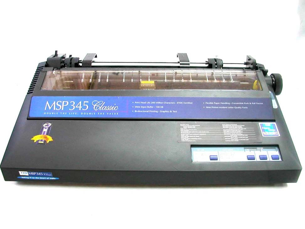
OSCMSP345CLASSIC
Oct 29, 2003PRINTER
Equipment Class
JBP - Part 15 Class B Computing Device Peripheral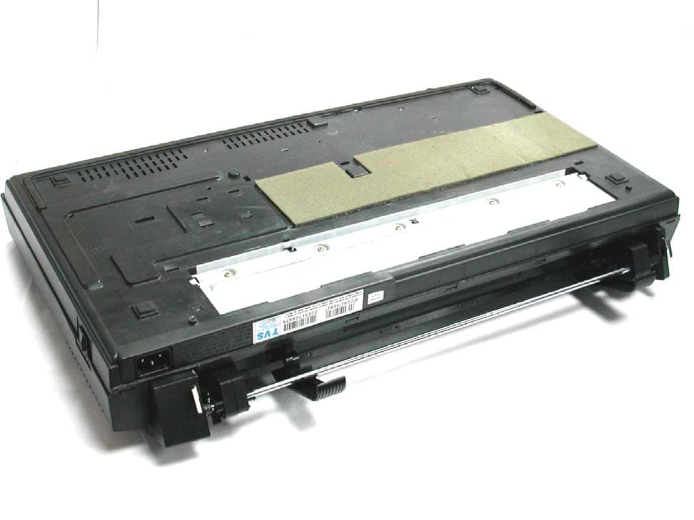
OSCMSP355XLC
Oct 29, 2003PRINTER
Equipment Class
JBP - Part 15 Class B Computing Device Peripheral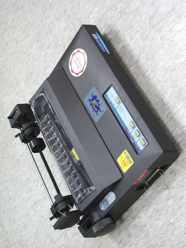
OSCMSP250
Apr 13, 2003Printer
Equipment Class
JBP - Part 15 Class B Computing Device Peripheral
OSCPROTON
Jul 28, 2002Printer
Equipment Class
JBP - Part 15 Class B Computing Device Peripheral
OSCMSP-245
Oct 29, 2001Printer
Equipment Class
JBP - Part 15 Class B Computing Device Peripheral