OSZ36342USpread Spectrum Transmitter
Conexant Systems Inc.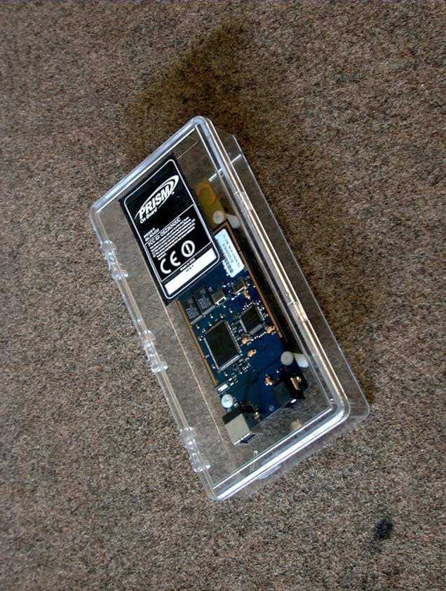
Click to zoom
Application Details
- Equipment Class
- DSS - Part 15 Spread Spectrum Transmitter
- Date of Grant
- Jul 29, 2001
- Application Purpose
- Original Equipment
- Date of Application
- Jul 28, 2001
- Equipment Note
- Spread Spectrum Transmitter
- Frequency Range
- 2412.00000000 - 2462.00000000
- Company
- Conexant Systems Inc.
- Country
- United States
Documents & Files
Document Text
Text extracted from the exhibit documents filed with the FCC. Open a document above to read the original.
Users Manual
1 TM I N C H E C K I N G AN9949 ISL36342U-EVAL PRISM II 11Mbps USB Wireless LAN Evaluation Kit User’s Guide Introduction This kit allows evaluation of the Intersil PRISM® II Direct Sequence chip set design in a Wireless Local Area Network (WLAN) USB Card implementation. Software drivers are included allowing data to be transmitted between cards at 1, 2, 5.5 and 11Mbps transfer rates, with a diagnostic program to display the real data throughput from system to system. Included in the kit are PRISM II chip set data sheets with application notes describing the implementation of a wireless networking card using the chip set. Contents of Your Evaluation Kit Your PC Card Wireless LAN Evaluation Kit contains the following items: Should you discover that your PC Card Wireless LAN Evaluation Kit is incomplete, please contact Intersil Corporation. Overview of IEEE 802.11 The IEEE 802.11 specification is a standard for wireless connectivity for fixed, portable, and moving stations within a local area. The IEEE 802.11 standard describes the services required by a compliant device to operate within an “ad hoc”or “infrastructure” network, as well as dealing with the issues related to mobility within those networks. Spread spectrum techniques are used to tolerate mobility and multipath effects. They are also a requirement for compliance with FCC, ETSI and those of other regulatory authorities when operating within the Industrial, Scientific, and Medical (ISM) frequency band. Anad hoccommunications network is created quickly and informally for a temporary time period. An infrastructure network usually requires more planning so that wireless stations can communicate over longer distances through access points, and may also communicate with existing wired LANs using portals. The IEEE 802.11 standard describes Media Access Control (MAC) procedures. The principal method of communication is the Carrier Sense Multiple Access with Collision Avoidance (CSMA-CA) protocol. Using this protocol, each station senses the communications medium (RF channel), and does not transmit until the channel is clear. This avoids collisions and minimizes the retransmission of subsequent packets. The standard also supports the operation of a station within a wireless LAN that may coexist with several overlapping wireless LANs. To accomplish this, a scheme of channelization and spread spectrum techniques is used. Direct Sequence (DSSS) and Frequency Hopping (FHSS) spread spectrum techniques are supported by the standard and both operate in the 2.4GHz to 2.4835GHz frequency band (the unlicensed ISM band). An infrared technique is also supported for indoor applications. The standard supports a 1Mbps and 2Mbps data rate for both DSSS and FHSS and has recently introduced a high data rate standard supporting 5.5Mbps and 11Mbps DSSS using Complementary Code Keying (CCK) modulation. The standard has also specified the requirements and services that enable private and secure communications to occur. Wireless LAN Configurations For ease of use in evaluating these cards, anad hoc network for peer to peer communications can be created. Anad hocnetwork is usually created for a specific purpose (such as file transfer or accessing a database).Ad hoc networks simplify the process of creating and dissolving networks for nontechnical users of the network facilities. Two cards form an IEEE 802.11 Independent Basic Service Set (IBSS), the simplestad hocnetwork. The cards communicate with each other directly and must remain within radio range. When both cards are on, they immediately “see” each other and thead hocnetwork is formed without user intervention. TousethecardsinaninfrastructureBSS(alsocalledan Extended Service Set) where the two cards may not be in direct radio contact, access points are needed. The association between a card (station) and an infrastructure BSS - where communication occurs only between a station and an access point and not between stations directly is dynamic. QUANTITYDESCRIPTION 2PRISMIIWirelessLANPCCards 1ISL36342U Wireless LAN Evaluation Kit User’s Guide, AN9949 1PRISM II Chip Set Data Sheets 1PRISM II Application Notes 1Microsoft® Windows® 98, 98SE, MS, Win2000 Drivers 1PRISM® Test Utilities (PTU) Software 1Features/Benefits Card 1Product Registration Form 1Notification Card Application NoteJune 2001 Author: Richard L. Abrahams 1-888-INTERSIL or 321-724-7143|Intersil and Design is a trademark of Intersil Americas Inc. Copyright © Intersil Americas Inc. 2001, All Rights Reserved PRISM® is a registered trademark of Intersil Americas Inc. PRISM and design is a trademark of Intersil Americas Inc. Microsoft® Windows® and Windows NT® are registered trademarks of Microsoft Corporation. LINUX® is a registered trademark of Linus Torvalds. 2 The IEEE 802.11 protocols are implemented in the firmware so that file transfers or database access can begin immediately. Direct Sequence Spread Spectrum Approach The use of spread spectrum techniques for wireless computer communications is widely accepted because of its robustness against multipath effects and interference from intentional or unintentional radiators. The use of spread spectrum techniques in the ISM frequency band also allows products to be deployed without the need for an FCC license. The two main methods by which spread spectrum communications can be achieved are Direct Sequence Spread Spectrum (DSSS) and Frequency Hopping Spread Spectrum (FHSS). This wireless LAN PC card uses the DSSS technique. DSSS transmission has the best performance in terms of multipath immunity and jamming rejection. In an office environment, jamming sources are likely to be unintentional such as emissions from microwave ovens. Even though unintentional, they pose a threat to the communications network. Direct sequence techniques are superior to frequency hopping systems in this case because FHSS gains its immunity to jamming by avoiding the location of a single tone jammer (such as other FHSS user…
Text truncated - open the document above for the full version.
Users Manual
Addendum 1 to Application Note 9949 CAUTION: To comply with FCC RF exposure compliance requirements, a separation distance of at least 20 cm must be maintained between the antenna of this device and all persons.
Cover Letter(s)
www.intersil.com ING Bank: 65.02.63.049 Swift code: INGBNL2A VAT / BRW: NL8039.66.659.B.01 Chamber of Commerce Utrecht: 30139807 Date 12 July 2001 Your reference -- Our reference Mansup/ds/2001_108 Subject Request for Non disclosure (FCC ID: OSZ36342U) Curtis-Straus LLC Attention: Certification Manager 527 Great Road Littleton, Massachusetts United States of America telephone: (978) 486-8880 fax: (978) 486-8828 Dear Certification manager, Persuant to 47 CFR Section 0.459, Intersil Corporation hereby requests non disclosure and confidential treatment of the following materials submitted in support of FCC certification application for FCC ID: OSZ36342U: a. Schematic diagrams b. Block diagram with operational description c. Bill of Material d. PCB layout Above materials contain trade secrets, proprietary and technical information which would customarily be guarded from competitors under 47 CFR section 0.457(d)(2). Disclosure or publication of any portion of this company confidential material to other parties could cause substantial competitive harm and provide unjustified benefits for competitors. Intersil Corporation understands that pursuant to 47 CFR section 0.457(d)(1)(ii) disclosure of the applicant and all accompanying documentation will not be made before the date of the grant. Sincerely yours, Derick Sariredjo Intersil Corp. Telephone: +31 30 225 97 42 email: [email protected]
Cover Letter(s)
Barry Quinlan From:"Sariredjo, Derick" <[email protected]> To:"'Certification Manager'" <[email protected]> Sent:Monday, July 23, 2001 9:49 AM Subject:RE: FCC ID: OSZ36342U Page 1 of 2 7/30/2001 Hi Barry, please find our response below: 1. The device is powered from the 5 Vdc from the USB port of PC host. This voltage is further regulated to 3.3 volts on the ISL36342u. The AC regulation comes from the host PC which maintains AC regulation < 1%. So Voltage variations on the PC Host AC mains power supply do not have significant effect on DC of the USB bus. 2. The data for the 2483.5 MHz is on page 106. The highest test frequency corresponds to channel 11 @ 2462.0 MHz. 3. The SMA connector is just for manufacturing test and is removed prior to shipment. The DC power jack is optional, and is intended to be shipped with each unit. The output of the DC supply is 4.5 to 6 volts over load and AC variations. This input is regulated to 3.3 Vdc. All circuity on the ISL36342U including the power amplifier run on 3.3Vdc. The total variation of the regulator over input voltage, load, temperture and set-on is < 2%. Therefore, the worst case variation possible on the transmitted power is 20*log(.98) = .18 dB 4. Final label material will be as below and is durable, tamper proof and legible: Material: Compucal II Tampermark MM 200 silver void II, Thickness: T=0.12mm (include single stick), Adhesive: V-23 adhesive" The labels on the photographs supplied are plain paper printed and only for pre-production indication purposes. I trust this clarifies the matter, Best regards, Derick -----Original Message----- From: Certification Manager [mailto:[email protected]] Sent: Thursday, July 19, 2001 9:33 PM To: Sariredjo, Derick Subject: FCC ID: OSZ36342U Hi Derick, We have identified these issues following our review of the application: 1. Please supply data responsive to the 15.31(e) power supply variation requirements. 2. Please supply or point us to the results for field strength at the band edge measurements at 2483.5MHz while transmitting at the highest operating channel. 3. Please confirm the SMA connector is not intended to have an antenna connected to it. 4. Please specify the label material. Best regards Barry C. Quinlan Certification & Telecom Manager ------------------------------------------------------------------------------- Curtis-Straus LLC Voice: 978.486.8880 x270 527 Great Road Fax: 978.486.8828 Littleton, MA 01460 http://www.curtis -straus.com -------------------------------------------------------------------------------- Page 2 of 2 7/30/2001
External Photos
FCC ID: OSZ36342U Page 1 of 5 Photographs of Description: 2.4 GHz USB WLAN FCC ID: OSZ36342U Brand name: Intersil Model number: ISL36342U FCC ID: OSZ36342U Page 2 of 5 ISL36342U exterior overview FCC ID: OSZ36342U Page 3 of 5 ISL36342U front view (digital) FCC ID: OSZ36342U Page 4 of 5 ISL36342U Rear view with shields (RF) FCC ID: OSZ36342U Page 5 of 5 ISL36342U Rear view without shields (RF)
ID Label/Location Info
FCC ID: OSZ36342U Page 1 of 3 FCC label information Description: 2.4 GHz USB WLAN FCC ID: OSZ36342U Brand name: Intersil Model number: ISL36342U FCC ID: OSZ36342U Page 2 of 3 ISL36342U FCC label FCC ID: OSZ36342U Page 3 of 3 ISL36342U label on cabinet
Internal Photos
FCC ID: OSZ36342U Page 1 of 5 Photographs of Description: 2.4 GHz USB WLAN FCC ID: OSZ36342U Brand name: Intersil Model number: ISL36342U FCC ID: OSZ36342U Page 2 of 5 ISL36342U exterior overview FCC ID: OSZ36342U Page 3 of 5 ISL36342U front view (digital) FCC ID: OSZ36342U Page 4 of 5 ISL36342U Rear view with shields (RF) FCC ID: OSZ36342U Page 5 of 5 ISL36342U Rear view without shields (RF)
RF Exposure Info
FCC ID: OSZ36342U 1 Engineering analysis of a low power DSSS spread spectrum Transceiver, Equipment description: 2.4GHz WLAN USB device Brand name: Intersil Model number: ISL36342U FCC ID: OSZ36342U According to requirements of : FCC part 15.247 (b) (4), FCC OET Bulletin 65 “Evaluating Compliance with FCC Guidelines for Human Exposure to Radio frequency Electromagnetic Fields “ and supplements A, B and C. Date: July 2, 2001 Author: D.S. Sariredjo, Intersil Corp. The Netherlands FCC ID: OSZ36342U 2 Introduction This engineering analysis was done according to FCC part 15.247 (b) (4) as part of the FCC certification requirements for spread spectrum devices. The measured EIRP values for the lowest, middle and highest TX channel were used for the MPE calculations based on FCC OET Bulletin 65 and supplements A, B, and C. These calculations were done in worst case mode, assuming 100% reflection of incoming radiation, resulting in a potential doubling of predicted field strength and a four-fold increase in (far-field equivalent) power density (S). EIRP S = 4πR 2 (power density without reflection) (2) 2 EIRP S = 4πR 2 (worst case power density with 100% reflection) with R = 20 cm (8 inches) Calculation results Table 1 below shows the Power density (S) results for the lowest, middle and highest TX channel: Measured EIRP (mW) Calculated worst case Power Density S (mW/cm 2 ) Ch 1 Ch 6 Ch 11 Ch 1 Ch 6 Ch 11 29.6 34.0 27.0 0.021 0.027 0.021 Table 1: Power density (S) calculations Conclusion Based on these calculations and using the limits of the general population / uncontrolled environment (which is 1.0 mW/cm 2 at 2.4 GHz), the Intersil low power spread spectrum transceiver does not exceed the MPE requirements set forth in documents above, with a minimum safe distance between antenna and operator of 20 centimeters (8 inches). The equipment therefore fulfills the requirements on power density for general population / uncontrolled exposure and therefore complies with the requirements of FCC Part 15.247(b)(4) and FCC OET Bulletin 65 incl. supplements A, B, and C.
Test Report
284 West Drive, Suite B Melbourne, FL 32904 RUBICOM SYSTEMS, INC. JANUARY 2001 Rubicom Systems, Inc. THIS REPORT SHALL NOT BE REPRODUCED EXCEPT IN FULL WITHOUT THE WRITTEN APPROVAL OF THE TESTING LABORATORY FCC TEST REPORT INTENTIONAL RADIATOR FOR THE INTERSIL CORPORATION 2.4GHz WIRELESS TRANSMITTER MODEL 36342U PRISM II USB JA-1758 2 TABLE OF CONTENTS Paragraph Title Page CERTIFICATION................................................................................................. 3 ABSTRACT......................................................................................................... 4 1.0 INTRODUCTION................................................................................................. 5 1.1 Purpose............................................................................................................... 5 1.2 Requirements ...................................................................................................... 5 1.3 Unit Under Test Description................................................................................. 7 1.4 Summary of Results ............................................................................................ 7 2.0 APPLICABLE DOCUMENTS.............................................................................. 8 3.0 TEST SITE DESCRIPTION................................................................................. 9 3.1 Environmental Conditions.................................................................................... 9 4.0 TEST INSTRUMENTATION.............................................................................. 10 5.0 TEST SAMPLE SETUP AND CONFIGURATIONS........................................... 11 6.0 PROCEDURES AND RESULTS....................................................................... 13 6.1 General ............................................................................................................. 13 6.2 Power Line Conducted 15.207 .......................................................................... 13 6.3 Radiated Emissions 15.209/15.205 ................................................................... 19 6.3.1 Radiated Emissions (Pre-Scans) ........................................................... 19 6.3.2 Radiated Emissions 15.209/15.205 ........................................................ 32 6.3.3 Peak Ambient (EUT Off/Support Equipment On) ................................... 32 6.4 Operation Within The Bands (2.4GHz-2.4835GHz)15.247(2)(b)(c)(d) ............... 81 6.4.1 6dB Bandwidth 15.247(2) ....................................................................... 81 6.4.2 Peak Output Power 15.247(2)(b) ........................................................... 89 6.4.3 Out of Band Emission 15.247(2)(c) ........................................................ 89 6.4.4 Power Spectral Density 15.247(2)(d) ................................................... 114 APPENDIX A COMPLIANCE LETTER............................................................................... 128 JA-1758 3 CERTIFICATION Rubicom Systems, Inc. certifies the information obtained in this report was performed consistent with the requirements of ANSI C63.4-1992. The Intersil Corporation Model 36342U, PRISM II USB, 2.4GHz Wireless Transmitter complies with the requirements of CFR 47 Part 15 for Intentional Radiators as required in Paragraph 15.247(a)(2)(b)(1)(c) and (d). This data was obtained while testing a 2.4GHz Wireless Transmitter, s/n: 00470005 furnished by Intersil Corporation. Any modifications to the unit as tested may invalidate the data and void this report. JA-1758 4 ABSTRACT This report presents test results of the emanations found emitting from the Intersil Corporation 2.4GHz Wireless Transmitter and the comparison of these emissions to the requirements of FCC Title 47, Part 15, Subpart C for Intentional Radiators as required for direct sequence type spread spectrum systems operating in the 2.4 to 2.4835GHz range. The testing was performed on a 3-meter open field test site at Rubicom Systems, Inc. (RSI). The testing was performed for Intersil under purchase order 040-0257435. The results of this test effort demonstrate compliance of the Intersil Corporation Model 36342U PRISM II USB, 2.4GHz Wireless Transmitter to FCC Title 47, Part 15, Subpart C for Intentional Radiators (Paragraph 247(2). The unit under test was serial number 00470005 for radiated and conducted measurements. JA-1758 5 1.0 INTRODUCTION 1.1 Purpose The purpose of the report is to show compliance of the Intersil Corporation Model 36342U PRISM II USB, 2.4GHz Wireless Transmitter to the requirements of Part 15 of the FCC Rules and Regulations (47CFR, Part 15, Subpart C) for Intentional Radiators. The applicable paragraphs covered by this report are 15.247(2)(b)(c) and (d). 1.2 Requirements The test requirements for an intentional radiator are as follows: RADIATED (15.205/15.209) Frequency (MHz) Field Strength (μV/m) Measurement Distance (m) 0.009-0.490MHz 2400/F (KHz) 300 0.490-1.705MHz 240000/F (KHz) 30 1.705-30.0MHz 30 30 30-88MHz 100 3 88-216MHz 150 3 216-960MHz 200 3 Above 960MHz 500 Average 3 CONDUCTED (15.207) Frequency (MHz) μ Volts dB>μV .450-30MHz 250 48 JA-1758 6 DIREST SEQUENCE SPREAD SPECTRUM SYSTEM 15.247(2) Bandwidth The minimum 6dB bandwidth shall be greater than 500KHz. 15.247(2)(b) Maximum Peak Power The Maximum peak output power of the transmitter shall not exceed 1 watt. 15.247(2)(c) Out of Band Emissions, Radiated and Conducted Power produced by Modulation Products of the Spreading Sequence, Information Sequence and the Carrier Frequency. Levels in any 100KHz outside of the frequency band shall be 20dB below that of any 100KHz band within the band that contains the highest level of desired power or the requirements of 15.209, whichever results in lesser attenuation. All other emissions shall not exceed the limits of Section 15.209(a). Section 15.205 requirements are applicable. 15.247(d) Pow…
Text truncated - open the document above for the full version.
Test Report
JA-1758 39 DATA SHEET 6.3.2-7 JA-1758 40 DATA SHEET 6.3.2-8 JA-1758 41 DATA SHEET 6.3.2-9 JA-1758 42 DATA SHEET 6.3.2-10 JA-1758 43 DATA SHEET 6.3.2-11 JA-1758 44 DATA SHEET 6.3.2-12 JA-1758 45 DATA SHEET 6.3.2-13 JA-1758 46 DATA SHEET 6.3.2-14 JA-1758 47 DATA SHEET 6.3.2-15 JA-1758 48 DATA SHEET 6.3.2-16 JA-1758 49 DATA SHEET 6.3.2-17 JA-1758 50 DATA SHEET 6.3.2-18 JA-1758 51 DATA SHEET 6.3.2-19 JA-1758 52 DATA SHEET 6.3.2-20 JA-1758 53 DATA SHEET 6.3.2-21 JA-1758 54 DATA SHEET 6.3.2-22 JA-1758 55 DATA SHEET 6.3.2-23 JA-1758 56 DATA SHEET 6.3.2-24 JA-1758 57 DATA SHEET 6.3.3-1 JA-1758 58 DATA SHEET 6.3.3-2 JA-1758 59 DATA SHEET 6.3.3-3 JA-1758 60 DATA SHEET 6.3.3-4 JA-1758 61 DATA SHEET 6.3.3-5 JA-1758 62 DATA SHEET 6.3.3-6 JA-1758 63 DATA SHEET 6.3.3-7 JA-1758 64 DATA SHEET 6.3.3-8 JA-1758 65 DATA SHEET 6.3.3-9 JA-1758 66 DATA SHEET 6.3.3-10 JA-1758 67 DATA SHEET 6.3.3-11 JA-1758 68 DATA SHEET 6.3.3-12 JA-1758 69 DATA SHEET 6.3.3-13 JA-1758 70 DATA SHEET 6.3.3-14 JA-1758 71 DATA SHEET 6.3.3-15 JA-1758 72 DATA SHEET 6.3.3-16 JA-1758 73 DATA SHEET 6.3.3-17 JA-1758 74 DATA SHEET 6.3.3-18 JA-1758 75 DATA SHEET 6.3.3-19 JA-1758 76 DATA SHEET 6.3.3-20 JA-1758 77 DATA SHEET 6.3.3-21 JA-1758 78 DATA SHEET 6.3.3-22 JA-1758 79 DATA SHEET 6.3.3-23
Test Report
JA-1758 79 DATA SHEET 6.3.3-23 JA-1758 80 DATA SHEET 6.3.3-24 6.4 Operation Within The Bands (2.4GHz-2.4835GHz)15.247(2)(b)(c)(d) JA-1758 81 6.4.1 6dB Bandwidth 15.247(2) The minimum 6dB bandwidth must be greater than 500KHz. Data Sheets 6.4.1-1 through 6.4.1-6 show the measured 6dB points to give bandwidths between 10.14 and 11.57MHz at the MIN, MID and MAX frequency tested. Data plots were made for the MIN and MAX data rates. The system exceeds the 500KHz minimum bandwidth. Photo 3 is representative of the 6dB bandwidth setup. JA-1758 82 PHOTO 3 JA-1758 83 DATA SHEET 6.4.1-1 JA-1758 84 DATA SHEET 6.4.1-2 JA-1758 85 DATA SHEET 6.4.1-3 JA-1758 86 DATA SHEET 6.4.1-4 JA-1758 87 DATA SHEET 6.4.1-5 JA-1758 88 DATA SHEET 6.4.1-6 JA-1758 89 6.4.2 Peak Output Power 15.247(2)(b) The peak output power to the antenna shall not exceed 1 watt. The unit under test (UUT) was configured to continuously transmit. The highest emission level within the authorized band was measured. The peak power level is recorded below. The carrier frequency of the UUT was 2412MHz, 2437MHz and 2462MHz. The MID, MIN and MAX data rates were used. The data is presented below for each frequency. All levels were below the 1 watt peak power limit. MIN TX FREQ. 2412GHz DATA RATE MIN - 14.7dBm MID - 14.7dBm MAX - 14.6dBm MID TX FREQ. 2437GHz DATA RATE MIN - 15.3dBm MID - 15.3dBm MAX - 15.2dBm MAX TX FREQ. 2462GHz DATA RATE MIN - 14.2dBm MID - 14.3dBm MAX - 14.3dBm 6.4.3 Out of Band Emission 15.247(2)(c) Out of band measurements were made on the antenna port of the RF unit. The measurement was made over the 2-25GHz range using the 100KHz RBW. Data Sheets 6.4.3-1 through 6.4.3-6 present the scan across the entire range at the MIN, MID and MAX frequency. The plot demonstrates that there is greater than 20dB separation between the intended signal and any other signals in the range. Data Sheets 6.4.3-7 is included to show the spectrum analyzer setup for restricted band testing where the start frequency and marker number “1” represented one restricted band (2.310-2.390GHz). Marker number “2” is the beginning of the 2.4835-2.5GHz restricted band. All signals falling into the restricted band were below the display line which represents the peak or average limit. These measurements were radiated measurements therefore are measured in both horizontal and vertical polarities. JA-1758 90 Data Sheets 6.4.3-8 through 6.4.3-15 present the peak and average measurements for the low channel at the MIN and MAX data rates. Data Sheets 6.4.3-16 through 6.4.3-23 present the same data for the highest channel. All signals that fall into the restricted bands are below the requirement of 15.209(a). JA-1758 91 DATA SHEET 6.4.3-1 JA-1758 92 DATA SHEET 6.4.3-2 JA-1758 93 DATA SHEET 6.4.3-3 JA-1758 94 DATA SHEET 6.4.3-4 JA-1758 95 DATA SHEET 6.4.3-5 JA-1758 96 DATA SHEET 6.4.3-6 JA-1758 97 DATA SHEET 6.4.3-7 JA-1758 98 DATA SHEET 6.4.3-8 JA-1758 99 DATA SHEET 6.4.3-9 JA-1758 100 DATA SHEET 6.4.3-10 JA-1758 101 DATA SHEET 6.4.3-11 JA-1758 102 DATA SHEET 6.4.3-12 JA-1758 103 DATA SHEET 6.4.3-13 JA-1758 104 DATA SHEET 6.4.3-14 JA-1758 105 JA-1758 106 DATA SHEET 6.4.3-15 JA-1758 107 DATA SHEET 6.4.3-16 JA-1758 108 DATA SHEET 6.4.3-17 JA-1758 109 DATA SHEET 6.4.3-18 JA-1758 110 DATA SHEET 6.4.3-19 JA-1758 111 DATA SHEET 6.4.3-20 JA-1758 112 DATA SHEET 6.4.3-21 JA-1758 113 DATA SHEET 6.4.3-22 JA-1758 114 DATA SHEET 6.4.3-23 6.4.4 Power Spectral Density 15.247(2)(d) The transmitted power density averaged over a 1 second interval shall not be greater than +8dBm in any 3KHz bandwidth within the band. The peak point was selected after a max hold was performed and the spectrum analyzer peak marker was positioned. The peak frequency was used as the center frequency. The RBW was set to 3KHz and the span width of 1.5MHz and sweep time of 500 seconds selected. Data Sheets 6.4.4-1 through 6.4.4-12 present the data plots for the three channels at the MIN and MAX data rates. The results show the spectral density to be greater than 20dB below the +8dBm requirement. Photo 4 is representative of this setup. JA-1758 115 PHOTO 4 JA-1758 116 DATA SHEET 6.4.4-1 JA-1758 117 DATA SHEET 6.4.4-2 JA-1758 118 DATA SHEET 6.4.4-3 JA-1758 119 DATA SHEET 6.4.4-4 JA-1758 120 DATA SHEET 6.4.4-5 JA-1758 121 DATA SHEET 6.4.4-6 JA-1758 122 DATA SHEET 6.4.4-7 JA-1758 123 DATA SHEET 6.4.4-8 JA-1758 124 DATA SHEET 6.4.4-9 JA-1758 125 DATA SHEET 6.4.4-10 JA-1758 126 DATA SHEET 6.4.4-11 JA-1758 127 DATA SHEET 6.4.4-12 JA-1758 128 APPENDIX A COMPLIANCE LETTER
Test Report
FCC ID: OSZ36342U FCC processing Gain report for -11Mbps at channel 1 -1, 2, 5.5 and 11 Mbps at channel 6 -11Mbps at channel 11 of Description: 2.4 GHz WLAN USB device FCC ID: OSZ36342U Brand name: Intersil Model number: ISL36342U intersil PRISM radio Jamming Margin Test _________________________________________________________________________________________________________ _____________________________________________________________________________________ intersil Page 1 Testing for compliance with FCC rules 15-247e Carl Andren intersil Corporation [email protected] 321-724-7535 Scope This report presents the test procedure, test configuration and test data associated with a FCC Part 15.247 (e) Jamming Margin test for the indirect measurement of processing gain. Applicable Reference Documents. 1. “Operation within the bands 902-928 MHz, 2400-2483.5, and 5725-5850 MHz” Title 47 Part 15 section 247 (e) Code of Federal Regulations. (47 CFR 15.247). 2. “Report and Order: Amendment of Parts 2 and 15 of the Commission’s Rules Regarding Spread Spectrum Transmitters. Appendix C: ‘Guidance on Measurements for Direct Sequence Spread Spectrum Systems” FCC 97-114. ET Docket No. 96-8, RM-8435, RM-8608, RM-8609. 3. “HFA3863 Direct Sequence Spread Spectrum Baseband Processor 4. “ M-ary Orthogonal Keying BER Curve”, Test Background and Procedure. According to FCC regulations [1], a direct sequence spread spectrum system must have a processing gain, G p of at least 10 dB. Compliance to this requirement can be shown by demonstrating a relative bit-error-ratio (BER) performance improvement (and corresponding signal to noise ratio per symbol improvement of at least 10 dB) between the case where spread spectrum processes (coding, modulation) are engaged relative to the processes being bypassed. In some practical systems, the spread spectrum processing cannot simply be bypassed. In these cases, the processing gain can be indirectly measured by a jamming margin test [2]. In accordance with the new NPRM 99-231, if the vendor has a system with less than 10 chips per symbol, the CW jamming results must be supported by a theoretical explanation of the system processing gain. intersil PRISM radio Jamming Margin Test _________________________________________________________________________________________________________ _____________________________________________________________________________________ intersil Page 2 Theoretical calculations The processing gain is related to the jamming margin as follows [2]: system output p L S J N S G+ + = Where BER REFERENCE is the reference bit error ratio with its corresponding, theoretical output signal to noise ratio per symbol, (S/N) output , (J/S) is the jamming margin (jamming signal power relative to desired signal power), and L system are the system implementation losses. The maximum allowed total system implementation loss is 2 dB. The HFA3863 direct sequence spread spectrum baseband processor uses CCK modulation which is a form of M-ary Orthogonal Keying. The BER performance curve is given by [5]: “ The probability of error for generalized M-ary Orthogonal signaling using coherent demodulation is given by: PPQz E z dz ec b M S N =− =−−+ − − − ∞ ∫ 11 1 2 212 2 1 2 1 2 01 0 π η ()exp This integral cannot be solved in closed form, and numerical integration must be used. This is done in a MATHCAD environment and is displayed in graphical format. intersil PRISM radio Jamming Margin Test _________________________________________________________________________________________________________ _____________________________________________________________________________________ intersil Page 3 1.1 1000 byte PER vs. Es/No 15.51616.517 10 -2 10 -1 10 0 11 Mbps CCK in Thermal Noise Es/No (dB) 1000 byte Packet Error Rate The reference PER is specified as 8% . The corresponding Es/No (signal to noise ratio per symbol) is 16.4 dB. The Es/No required to achieve the desired BER with maximum system implementation losses is 18.4 dB. The minimum processing gain is again, 10 dB, therefore: dB S J dBdBL S J N E G system output o s p 100.24.16≥ ++=+ + = dB S J dBG p 104.18≥ += The minimum jammer to signal ratio is as follows: dB S J 4.8−≥ For the case of the HFA3863, the bit rates are 1, 2, 5.5, and 11 Mbps. The corresponding symbol rates are 1, 1, 1.375, and 1.375 MSps. The chip rate is always 11 MCps, so the ratio of chip rate to symbol rate is 11:1 for the 1 and 2 Mbps rates and 8:1 for the 5.5 and 11 Mbps rates. Since the symbol rate to bit rate is less than 10 for the higher rates, we supply the theoretical processing gain calculation for these cases where both spread spectrum intersil PRISM radio Jamming Margin T…
Text truncated - open the document above for the full version.
Contact Information
Applicant
Derick Sariredjo
Test Firm
Advanced Compliance Solutions, Inc.Sam Wismer
Technical Specifications
| # | Rule Parts | Frequency Range | Power Output |
|---|---|---|---|
| 1 | 15C | 2.41 GHz - 2.46 GHz | 34.00 mW |
Other Applications from Conexant Systems Inc.
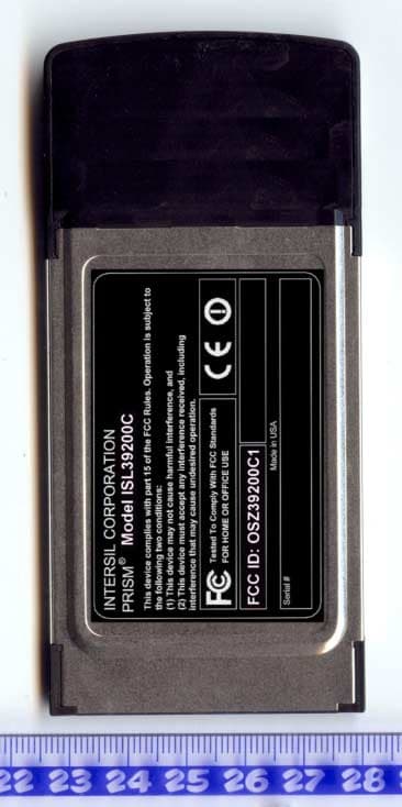
OSZ39200C1
Dec 08, 20032.4/5 GHz IEEE 802.11g/a WLAN Cardbus card
Equipment Class
NII - Unlicensed National Information Infrastructure TX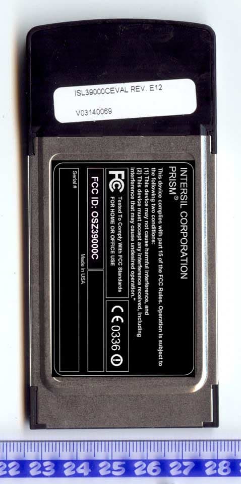
OSZ39000C
Oct 19, 20032.4/5 GHz IEEE 802.11g/a WLAN Cardbus card
Equipment Class
DTS - Digital Transmission System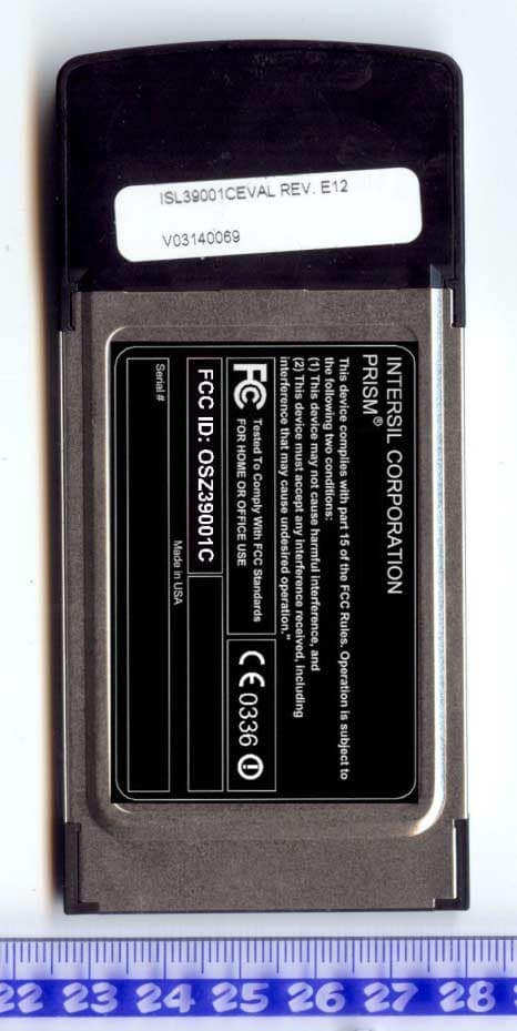
OSZ39001C
Oct 19, 20032.4/5 GHz IEEE 802.11g/a WLAN Cardbus card
Equipment Class
DTS - Digital Transmission System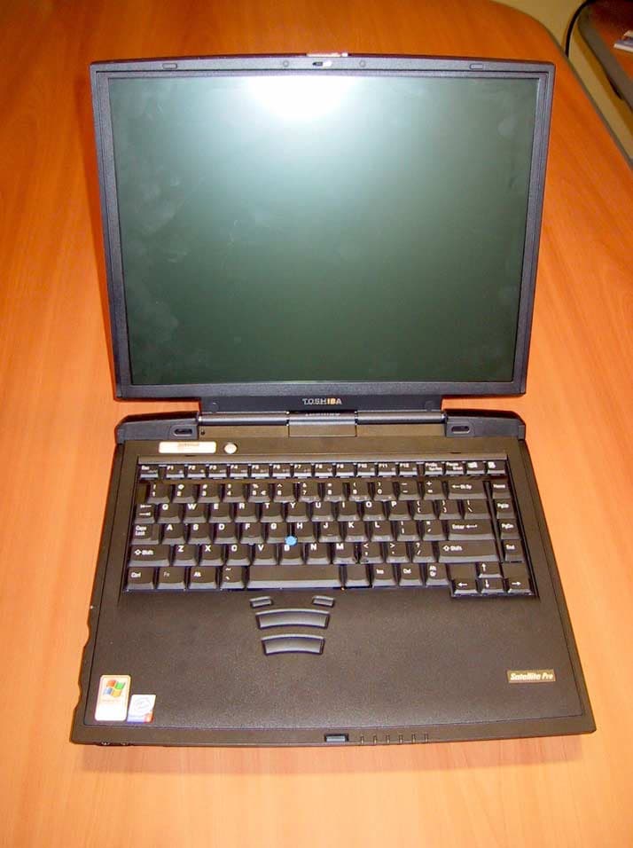
OSZ39000M1
Aug 20, 20032.4 GHz/5 GHz IEEE 802.11a/g WLAN MiniPCI card
Equipment Class
NII - Unlicensed National Information Infrastructure TX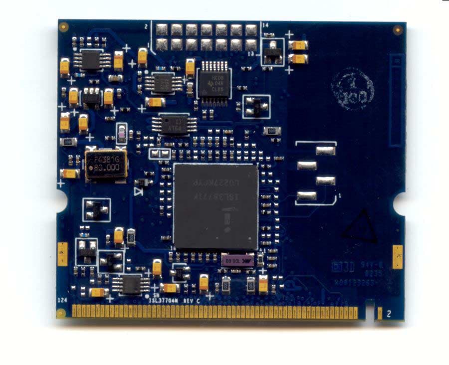
OSZ37704M
May 26, 20035 GHz IEEE 802.11a WLAN MiniPCI card
Equipment Class
NII - Unlicensed National Information Infrastructure TX