OSZ39200C12.4/5 GHz IEEE 802.11g/a WLAN Cardbus card
Conexant Systems Inc.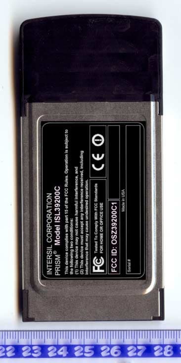
Click to zoom
Application Details
- Equipment Class
- NII - Unlicensed National Information Infrastructure TX
- Date of Grant
- Dec 08, 2003
- Application Purpose
- Original Equipment
- Date of Application
- Dec 08, 2003
- Equipment Note
- 2.4/5 GHz IEEE 802.11g/a WLAN Cardbus card
- Frequency Range
- 5250.00000000 - 5350.00000000
- Company
- Conexant Systems Inc.
- Country
- United States
Documents & Files
Document Text
Text extracted from the exhibit documents filed with the FCC. Open a document above to read the original.
Users Manual
Preliminary User manual FCC ID: OSZ39200C1 Page 1 of 7 Intersil ISL39200C IEEE 802.11a/g WLAN Cardbus32 Card User Manual Version 0.3 Preliminary User manual FCC ID: OSZ39200C1 Page 2 of 7 Table of Contents 0-INTRODUCTION ....................................................................................................3 1-INSTALLATION PROCEDURE ...........................................................................3 1.1 I NSTALLING THE CARDBUS32 CARD INTO THE ACCESS POINT.........................3 1.2 WIRELESS LAN INSTALLATION GUIDE LINES AND AUTHORIZATION FOR USE.4 2-REGULATORY INFORMATION.........................................................................4 2.1 FCC I NFORMATION TO USER.............................................................................4 2.2 FCC G UIDELINES FOR HUMAN EXPOSURE........................................................4 2.3 FCC ELECTRONIC EMISSION NOTICES..............................................................4 2.4 FCC RADIO FREQUENCY INTERFERENCE STATEMENT.....................................5 2.5 E XPORT RESTRICTIONS.......................................................................................5 2.6 EUROPE - EU DECLARATION OF CONFORMITY.................................................6 3-TECHNICAL SPECIFICATIONS .........................................................................7 Preliminary User manual FCC ID: OSZ39200C1 Page 3 of 7 0-Introduction The Intersil ISL39200C WLAN NIC is a complete wireless high speed Network Interface Card (NIC). It conforms to the IEEE 802.11g and IEEE 802.11a protocol and operates in the 2.45 GHz and 5150-5350MHz, 5470-5725MHz and 5725-5825 MHz frequency bands. It provides a complete reference design evaluation platform of hardware and software to system providers or integrators requiring wireless data communications capability and is ideal for integration into Access Points. ï Fully compliant with the IEEE 802.11g and IEEE 802.11a WLAN standards ï FCC Certified Under Part 15 (pending) to Operate in the 2.45 GHz and 5150-5350MHz, 5725-5825 MHz Bands ï ETSI Certified Under RTTE directive (pending) to Operate in the 2.45 GHz and 5150-5350MHz, 5470-5725MHz and 5725-5825 MHz Bands ï Support for 54, 48, 36, 24, 18, 12, 9, and 6 Mbps OFDM, 11 and 5.5 Mbps CCK and legacy 2 and 1 Mbps data rates This Cardbus card is only intended to be used in combination with the integrated firmware/drivers of Access Points. The firmware in this Cardbus card will not allow an user to install this Cardbus card into other devices than Access Points and/or use this Cardbus card in combination with other drivers than those which are readily available in Access Points. 1-Installation procedure 1.1 Installing the Cardbus32 card into the Access Point Turn the Access Point off and then insert Cardbus card into the Cardbus slot of the Access Point. Further details of how to install the Cardbus card into the Access Point and how to configure the Cardbus card for proper operation may be found in the installation manual of the Access Point. CAUTION: 1-- This assembly is designed to operate with a supply voltage of 3.3V in Access Points supporting the CARDBUS32 standard. 2-- Do not force engagement of the card in the CARDBUS32 slot. It is mechanically designed to prevent improper insertion. Preliminary User manual FCC ID: OSZ39200C1 Page 4 of 7 1.2 Wireless LAN installation guide lines and Authorization for use Installation and use of this Wireless LAN device must be in strict accordance with the instructions included in the user documentation provided with the product. Any changes or modifications made to this device that are not expressly approved by Intersil may void the userís authority to operate the equipment. Intersil is not responsible for any radio or television interference caused by unauthorized modification of this device, or the substitution or attachment of connecting cables and equipment other than specified. It is the responsibility of the user to correct any interference caused by such unauthorized modification, substitution or attachment. Intersil and its authorized resellers or distributors will assume no liability for any damage or violation of government regulations arising from failing to comply with these guidelines. The use of Wireless LAN devices may be restricted in some situations or environments for example: * On board of airplanes, or * In an explosive environment, or * In case the interference risk to other devices or services is perceived or identified as harmful. In case the policy regarding the use of Wireless LAN devices in specific organizations or environments (e.g. airports, hospitals, chemical/oil/gas industrial plants, private buildings etc.) is not clear, please first verify authorization to use these devices prior to operating the equipment. 2-Regulatory information 2.1 FCC Information to User This product does not contain any user serviceable components and is to be used with approved antennas only. Any product changes or modifications will invalidate all applicable regulatory certifications and approvals 2.2 FCC Guidelines for Human Exposure In order to comply with RF exposure limits, the user is advised to maintain a distance of at least 20 cm from the antenna of this device while it is in use. 2.3 FCC Electronic Emission Notices This device complies with part 15 of the FCC Rules. Operation is subject to the following two conditions: 1. This device may not cause harmful interference 2. This device must accept any interference received, including interference that may cause undesired operation. Caution: 1--Within 5.15 to 5.25 MHz bands, UNII devices are restricted to indoor operations to reduce any potential harmfull interference to co-channel Mobile Satelite Systems (MSS) operations. 2--High power radars are allocated as primary users in the 5.25 to 5.35GHz and 5.65 to 5.85GHz bands. These high power radar stations can cause interference with and/or damage to this device. Prelimin…
Text truncated - open the document above for the full version.
Cover Letter(s)
TNO Electronic Products & Services (EPS) B.V. Nederlandse Organisatie voor toegepast-natuurwetenschappelijk onderzoek / Netherlands Organisation for Applied Scientific Research Smidshornerweg 18 P.O. Box 15 9822 ZG Niekerk The Netherlands www.tno.nl T +31 594 505005 F +31 594 504804 E [email protected] Subject Cover letter Date August 28, 2003 Our reference 03K1023a Your reference - Page 1 of 1 Our General Terms and Conditions, as filed at the Chamber of Commerce in Groningen, are applicable to all orders given to TNO Electronic Products & Services (EPS) B.V. TNO Electronic Products & Services (EPS) B.V. is registered at the Chamber of Commerce in Groningen with no. 27247331. Return address: P.O. Box 15, 9822 ZG Niekerk, The Netherlands Telefication B.V. Attn.: W. Blom Edisonstraat 12a 6902 PK Zevenaar The Netherlands Dear Mr. Blom, On behalf of our customer Intersil Corporation, we hereby would like to apply for FCC certification (full modular approval, see also excerpt of DA 00-1407 and remarks below) of the following device: FCC ID : OSZ39200C1 Brand : Intersil Model number : ISL39200C Description : 2.4/5 GHz IEEE 802.11g/a WLAN Cardbus card The following PDF files (exhibits) are electronically submitted: 1. Cover letter containing the request for FCC certification 2. Request for confidentiality 3. Test report(s) in conformity with 47 CFR Part 15 (a) Test report 47 CFR Part 15.247 (2412 ñ 2462 MHz) (b) Test report 47 CFR Part 15.247 (5725 ñ 5850 MHz) (c) Test report 47 CFR Part 15.407 (5150 ñ 5350 MHz) 4. Bill of materials 5. Circuit diagram 6. Block diagram 7. Operational description 8. Interior photographs 9. Exterior photographs 10. Test setup photographs 11. RF exposure statement 12. Authorization letter 13. User manual 14. Label information Best regards, TNO Electronic Products & Services (EPS) B.V. P.A.J.M. Robben, B.Sc.E.E. Marketing Manager Nederlandse Organisatie voor toegepast-natuurwetenschappelijk onderzoek / Netherlands Organisation for Applied Scientific Research Date August 28, 2003 Our reference 03K1023a Your reference - Page 2 of 3 Excerpt of DA 00-1407 In order to obtain a modular transmitter approval, a cover letter requesting modular approval must be submitted and the numbered requirements identified below must be addressed in the application for equipment authorization. 1. The modular transmitter must have its own RF shielding. This is intended to ensure that the module does not have to rely upon the shielding provided by the device into which it is installed in order for all modular transmitter emissions to comply with Part 15 limits. It is also intended to prevent coupling between the RF circuitry of the module and any wires or circuits in the device into which the module is installed. Such coupling may result in non-compliant operation. Remark: The modular transmitter has its own RF shielding. 2. The modular transmitter must have buffered modulation/data inputs (if such inputs are provided) to ensure that the module will comply with Part 15 requirements under conditions of excessive data rates or over-modulation. Remark: The transmitter has buffered modulation/data inputs. 3. The modular transmitter must have its own power supply regulation. This is intended to ensure that the module will comply with Part 15 requirements regardless of the design of the power supplying circuitry in the device into which the module is installed. Remark: The transmitter has its own integrated and dedicated power supply regulation. 4. The modular transmitter must comply with the antenna requirements of Section 15.203 and 15.204(c). The antenna must either be permanently attached or employ a ìuniqueî antenna coupler (at all connections between the module and the antenna, including the cable). Any antenna used with the module must be approved with the module, either at the time of initial authorization or through a Class II permissive change. The ìprofessional installationî provision of Section 15.203 may not be applied to modules. Remark: The modular transmitter has an integral antenna. 5. The modular transmitter must be tested in a stand-alone configuration, i.e., the module must not be inside another device during testing. This is intended to demonstrate that the module is capable of complying with Part 15 emission limits regardless of the device into which it is eventually installed. Unless the transmitter module will be battery powered, it must comply with the AC line conducted requirements found in Section 15.207. AC or DC power lines and data input/output lines connected to the module must not contain ferrites, unless they will be marketed with the module (see Section 15.27(a)). The length of these lines shall be length typical of actual use or, if that length is unknown, at least 10 centimeters to insure that there is no coupling between the case of the module and supporting equipment. Any accessories, peripherals, or support equipment connected to the module during testing shall be unmodified or commercially available (see Section 15.31(i)). Nederlandse Organisatie voor toegepast-natuurwetenschappelijk onderzoek / Netherlands Organisation for Applied Scientific Research Date August 28, 2003 Our reference 03K1023a Your reference - Page 3 of 3 Remark: The modular transmitter has been tested in a stand-alone configuration (by using a Carbus extender card) in order to demonstrate that the module is capable of complying with Part 15 emission limits regardless of the device into which it is eventually installed. 6. The modular transmitter must be labeled with its own FCC ID number, and, if the FCC ID is not visible when the module is installed inside another device, then the outside of the device into which the module is installed must also display a label referring to the enclosed module. This exterior label can use wording such as the following: ìContains Transmitter Module FCC ID: XYZMODEL1î or ìContains FCC ID: XYZMODEL1.î Any similar wording that expresses the same meaning may …
Text truncated - open the document above for the full version.
Cover Letter(s)
TNO Electronic Products & Services (EPS) B.V. Nederlandse Organisatie voor toegepast-natuurwetenschappelijk onderzoek / Netherlands Organisation for Applied Scientific Research Smidshornerweg 18 P.O. Box 15 9822 ZG Niekerk The Netherlands www.tno.nl T +31 594 505005 F +31 594 504804 E [email protected] Subject Request for confidentiality Date August 29, 2003 Our reference 03K1023b Your reference - Page 1 of 1 Our General Terms and Conditions, as filed at the Chamber of Commerce in Groningen, are applicable to all orders given to TNO Electronic Products & Services (EPS) B.V. TNO Electronic Products & Services (EPS) B.V. is registered at the Chamber of Commerce in Groningen with no. 27247331. Return address: P.O. Box 15, 9822 ZG Niekerk, The Netherlands Telefication B.V. Attn.: W. Blom Edisonstraat 12a 6902 PK Zevenaar The Netherlands Dear Mr. Blom, Pursuant to section 0.457 of the FCC rules we herewith request the following exhibits, related to this application for FCC ID: OSZ39200C1, to be withheld from public inspection and to be kept confidential. The contents of these exhibits may not be disclosed to other parties than Intersil Corporation and TNO Electronic Products & Services (EPS) B.V.: 1. Bill of materials 2. Circuit diagram 3. Operational description 4. Block diagram The reason for this request for confidentiality is that the information contained in the exhibits as listed above has been classified as company confidential. Disclosure of any portion of this information to other parties would cause substantial competitive harm. Best regards, TNO Electronic Products & Services (EPS) B.V. P.A.J.M. Robben, B.Sc.E.E. Marketing Manager
Cover Letter(s)
www.intersil.com ING Bank: 65.02.63.049 Swift code: INGBNL2A VAT / BRW: NL8039.66.659.B.01 Chamber of Commerce Utrecht: 30139807 Date 20 August 2003 Your reference -- Our reference 2003-mansup-615b Subject Agent authorization letter for FCC ID: OSZ39200C1 To whom it may concern To whom it may concern, This letter confirms the agreement that; TNO Electronic Products & Services (EPS) B.V. Smidshornerweg 18 9822 TL Niekerk The Netherlands is authorized as an agent for Company Intersil Corp. The Netherlands Address, City Rembrandtlaan 1a, Bilthoven Country The Netherlands Phone number +31 30 2296060 Fax number +31 30 2296061 and is authorized to sign application forms and act on behalf of Intersil Corp. The Netherlands and is authorized to receive and exchange data between Intersil Corp. The Netherlands and European/non-European national authorities regarding the -certification of- and/or -arranging type approvals for the following product: Intersil model ISL39200C WLAN Cardbus Card with FCC ID: OSZ39200C1 This authorization will expire on December, 2003 or upon earlier written notice from Intersil Corp. The Netherlands. Yours sincerely, Derick Sariredjo ( [email protected] ) Intersil Corp. The Netherlands ( www.intersil.com ) Rembrandtlaan 1a, 3723 BG Bilthoven, The Netherlands Phone: +31.30.225.9742 Fax: +31.30.229.6061
External Photos
FCC ID: OSZ39200C1 Page 1 of 3 External photographs of Description: 2.4 GHz / 5 GHz Dual band WLAN Cardbus Card FCC ID: OSZ39200C1 Brand name: Intersil Model number: ISL39200C FCC ID: OSZ39200C1 Page 2 of 3 ISL39200C Front exterior FCC ID: OSZ39200C1 Page 3 of 3 ISL39200C back exterior
ID Label/Location Info
FCC ID: OSZ39200C1 Page 1 of 4 FCC and CE Label info of Description: 2.4 GHz / 5GHz dual band WLAN Cardbus Card FCC ID: OSZ39200C1 Brand name: Intersil Model number: ISL39200C FCC ID: OSZ39200C1 Page 2 of 4 ISL39200C FCC and CE Label Label material: Tamper evident 0.002" polyester. This material is durable, tamper proof and legible. Tamper proof: If the label is removed after 48 hours (time for the adhesive to cure) it will separate which will leave label material on the attached surface that it was removed from. This label material will spell out the word "VOID". The label will also show the word "VOID" where the label material was pulled away. The end result is the word " VOID " on both the mating surface and label, leaving both unusable. FCC ID: OSZ39200C1 Page 3 of 4 ISL39200C Front label on Cover set FCC ID: OSZ39200C1 Page 4 of 4 ISL3920C FCC and CE Back label on Cover set
Internal Photos
FCC ID: OSZ39200C1 Page 1 of 4 Internal photographs of Description: 2.4 GHz / 5 GHz WLAN Cardbus Card FCC ID: OSZ39200C1 Brand name: Intersil Model number: ISL39200C FCC ID: OSZ39200C1 Page 2 of 4 ISL39200C PCB front with shield FCC ID: OSZ39200C1 Page 3 of 4 ISL39200C PCB front without shield FCC ID: OSZ39200C1 Page 4 of 4 ISL39200C PCB rear
RF Exposure Info
Declaration on radiation safety standard conformance To whom it may concern: Intersil Corporation Rembrandtlaan 1a 3723 BG Bilthoven The Netherlands declares that the following product Description: 2.4/5 GHz IEEE 802.11g/a WLAN Cardbus card FCC ID: OSZ39200C1 Manufacturer: Intersil Corporation Brand: Intersil Model: ISL39200C (1) has a maximum e.i.r.p. of 18.2 dBm (66 mW, maximum conducted output power of +20 dbm minus antenna gain of ñ1.8 dBi) in the frequency range of 2412 ñ 2462 MHz, which means that the worst case prediction of power density (100% reflection) at 20 cm distance (worst case) can be calculated as follows : EIRP S = 4*π * R 2 (power density without reflection) 2 2 *EIRP S = 4*π * R 2 (power density with 100% reflection) 2 2 *EIRP 66.1 mW S = 4*π * R 2 = π*(20cm) 2 = 0.053 mW/cm 2 (limit = 1.0 mW/cm 2 ) This means that according to OET Bulletin 65 (Edition 97-01), Supplement C (Edition 01-01), the equipment fulfills the requirements on power density for general population/uncontrolled exposure and therefore fulfills the requirements of 47 CFR Part 15.247 (b)(5). (2) has a maximum e.i.r.p. of 18.0 dBm (63.1 mW, maximum conducted output power of +19.8 dbm minus antenna gain of ñ1.8 dBi) in the frequency range of 5150 ñ 5350 MHz, which means that the worst case prediction of power density (100% reflection) at 20 cm distance (worst case) can be calculated as follows : EIRP S = 4*π * R 2 (power density without reflection) 2 2 *EIRP S = 4*π * R 2 (power density with 100% reflection) 2 2 *EIRP 63.1 mW S = 4*π * R 2 = π*(20cm) 2 = 0.050 mW/cm 2 (limit = 1.0 mW/cm 2 ) This means that according to OET Bulletin 65 (Edition 97-01), Supplement C (Edition 01-01), the equipment fulfills the requirements on power density for general population/uncontrolled exposure and therefore fulfills the requirements of 47 CFR Part 15.407 (f). (3) has a maximum e.i.r.p. of 17.6 dBm (57.5 mW, maximum conducted output power of +19.4 dbm minus antenna gain of ñ1.8 dBi) in the frequency range of 5725 ñ 5850 MHz, which means that the worst case prediction of power density (100% reflection) at 20 cm distance (worst case) can be calculated as follows : EIRP S = 4*π * R 2 (power density without reflection) 2 2 *EIRP S = 4*π * R 2 (power density with 100% reflection) 2 2 *EIRP 57.5 mW S = 4*π * R 2 = π*(20cm) 2 = 0.045 mW/cm 2 (limit = 1.0 mW/cm 2 ) This means that according to OET Bulletin 65 (Edition 97-01), Supplement C (Edition 01-01), the equipment fulfills the requirements on power density for general population/uncontrolled exposure and therefore fulfills the requirements of 47 CFR Part 15.247 (b)(5).
Test Report
Testing and certification of electric, electronic and radio equipment/installations including telecommunication systems TNO Electronic Products & Services (EPS) B.V. P.O. Box 15 9822 ZG Niekerk (NL) Smidshornerweg 18 9822 TL Niekerk (NL) Telephone: +31 594 505005 Telefax: +31 594 504804 E-mail: [email protected] Web: www.eps.tno.nl Project number: 03082003.r04.rev1 Page 1 of 96 TEST REPORT OF A 2.4/5 GHZ IEEE 802.11g/a WLAN CARDBUS CARD, BRAND INTERSIL, MODEL ISL39200C, IN CONFORMITY WITH 47 CFR PART 15 (2003-03-13). FCC listed Industry Canada VCCI registered : : : 90828 IC3501 R-1518, C-1598 Test specification(s): Description of EUT: Manufacturer: Brand mark: Model: FCC ID: 47 CFR Part 15 (2003-03-13) 2.4/5 GHz IEEE 802.11g/a WLAN Cardbus card Intersil Corporation Intersil ISL39200C OSZ39200C1 Project number: 03082003.r04.rev1 Page 2 of 96 MEASUREMENT/TECHNICAL REPORT Intersil Corporation Model : ISL39200C FCC ID: OSZ39200C1 December 1, 2003 This report concerns: Original grant/certification Class 2 change Verification Equipment type: Unlicensed U-NII Device Deferred grant requested per 47 CFR 0.457(d)(1)(ii) ? Yes No Report prepared by: Name : P.A.J.M. Robben, B.Sc.E.E. Company name : TNO Electronic Products & Services (EPS) B.V. Address : Smidshornerweg 18 Postal code/city : 9822 ZG Niekerk Mailing address : P.O. Box 15 Postal code/city : 9822 TL Niekerk Country : The Netherlands Telephone number : + 31 594 505 005 Telefax number : + 31 594 504 804 E-mail : [email protected] The data taken for this test and report herein was done in accordance with 47 CFR Part 15 and the measurement procedures of ANSI C63.4-1992. TNO Electronic Products & Services (EPS) B.V. at Niekerk, The Netherlands, certifies that the data is accurate and contains a true representation of the emission profile of the Equipment Under Test (EUT) on the date of the test as noted in the test report. I have reviewed the test report and find it to be an accurate description of the test(s) performed and the EUT so tested. Date: December 1, 2003 Signature: P. de Beer TNO Electronic Products & Services (EPS) B.V. Test specification(s): Description of EUT: Manufacturer: Brand mark: Model: FCC ID: 47 CFR Part 15 (2003-03-13) 2.4/5 GHz IEEE 802.11g/a WLAN Cardbus card Intersil Corporation Intersil ISL39200C OSZ39200C1 Project number: 03082003.r04.rev1 Page 3 of 96 Description of test item Test item : 2.4/5 GHz IEEE 802.11g/a WLAN Cardbus card Manufacturer : Intersil Corporation Brand : Intersil Model : ISL39200C Serial numbers : 03290022 Revision : B3 Receipt number : 1 Receipt date : August 18, 2003 Applicant information Applicant's representative : Mr. D. Sariredjo Company : Intersil Corporation Address : Rembrandtlaan 1a Postal code : 3723 BG City : Bilthoven PO-box : 343 Postal code : 3720 AH City : Bilthoven Country : The Netherlands Telephone number : +31 30 2259742 Telefax number : +31 30 2296061 Test(s) performed Location : Niekerk Test(s) started : August 18, 2003 Test(s) completed : August 28, 2003 Purpose of test(s) : Type approval / certification Test specification(s) : 47 CFR Part 15 (2003-03-13) Test engineer : O.H. Hoekstra H.J. Pieters Report written by : P.A.J.M. Robben, B.Sc.E.E. Project leader : P.A.J.M. Robben, B.Sc.E.E. This report is in conformity with NEN-EN-ISO/IEC 17025: 2000. This report shall not be reproduced, except in full, without the written permission of TNO Electronic Products & Services (EPS) B.V. The test results relate only to the item(s) tested. Test specification(s): Description of EUT: Manufacturer: Brand mark: Model: FCC ID: 47 CFR Part 15 (2003-03-13) 2.4/5 GHz IEEE 802.11g/a WLAN Cardbus card Intersil Corporation Intersil ISL39200C OSZ39200C1 Project number: 03082003.r04.rev1 Page 4 of 96 Table of contents 1 General information................................................................................................................................................................. 6 1.1 Product description. ......................................................................................................................................................... 6 1.2 Related submittal(s) and/or Grant(s). .............................................................................................................................. 6 1.3 Tested system details. ...................................................................................................................................................... 6 1.4 Test methodology. ........................................................................................................................................................... 7 1.5 Test facility. ..................................................................................................................................................................... 7 1.6 Product labeling. .............................................................................................................................................................. 7 1.7 System test configuration. ............................................................................................................................................... 8 1.7.1 Justification.............................................................................................................................................................. 8 1.7.2 EUT test software. ................................................................................................................................................... 8 1.8 Special accessories. ......................................................................................................................................................... 8 1.9 Equipment modifications................................................................................................................................................. 8 1.10 Configuration of the tested system. .............................…
Text truncated - open the document above for the full version.
Test Setup Photos
Testing and certification of electric, electronic and radio equipment/installations including telecommunication systems TNO Electronic Products & Services (EPS) B.V. P.O. Box 15 9822 ZG Niekerk (NL) Smidshornerweg 18 9822 TL Niekerk (NL) Telephone: +31 594 505005 Telefax: +31 594 504804 E-mail: [email protected] Web: www.eps.tno.nl Project number: 03082003.p01 Page 1 of 7 47 CFR PART 15 TEST SETUP PHOTOGRAPHS OF A 2.4/5 GHZ IEEE 802.11g/a WLAN CARDBUS CARD, BRAND INTERSIL, MODEL ISL39200C. FCC listed Industry Canada VCCI registered : : : 90828 IC3501 R-1518, C-1598 Description of EUT: Manufacturer: Brand mark: Model: FCC ID: 2.4/5 GHz IEEE 802.11g/a WLAN Cardbus card Intersil Corporation Intersil ISL39200C OSZ39200C1 Project number: 03082003.p01 Page 2 of 7 Description of test item Test item : 2.4/5 GHz IEEE 802.11g/a WLAN Cardbus card Manufacturer : Intersil Corporation Brand : Intersil Model : ISL39200C Serial numbers : 03290022 Revision : B3 Receipt number : 1 Receipt date : August 18, 2003 Applicant information Applicant's representative : Mr. D. Sariredjo Company : Intersil Corporation Address : Rembrandtlaan 1a Postal code : 3723 BG City : Bilthoven PO-box : 343 Postal code : 3720 AH City : Bilthoven Country : The Netherlands Telephone number : +31 30 2259742 Telefax number : +31 30 2296061 This report is in conformity with NEN-EN-ISO/IEC 17025: 2000. This report shall not be reproduced, except in full, without the written permission of TNO Electronic Products & Services (EPS) B.V. The test results relate only to the item(s) tested. Description of EUT: Manufacturer: Brand mark: Model: FCC ID: 2.4/5 GHz IEEE 802.11g/a WLAN Cardbus card Intersil Corporation Intersil ISL39200C OSZ39200C1 Project number: 03082003.p01 Page 3 of 7 Table of contents 1 Radiated emission test setup.................................................................................................................................................... 4 1.1 Radiated emission test setup (front). ............................................................................................................................... 4 1.2 Radiated emission test setup (back). ............................................................................................................................... 5 2 Conducted emission test setup................................................................................................................................................. 6 2.1 Conducted emission test setup (front). ............................................................................................................................ 6 2.2 Conducted emission test setup (back). ............................................................................................................................ 7 Description of EUT: Manufacturer: Brand mark: Model: FCC ID: 2.4/5 GHz IEEE 802.11g/a WLAN Cardbus card Intersil Corporation Intersil ISL39200C OSZ39200C1 Project number: 03082003.p01 Page 4 of 7 1 Radiated emission test setup. 1.1 Radiated emission test setup (front). Description of EUT: Manufacturer: Brand mark: Model: FCC ID: 2.4/5 GHz IEEE 802.11g/a WLAN Cardbus card Intersil Corporation Intersil ISL39200C OSZ39200C1 Project number: 03082003.p01 Page 5 of 7 1.2 Radiated emission test setup (back). Description of EUT: Manufacturer: Brand mark: Model: FCC ID: 2.4/5 GHz IEEE 802.11g/a WLAN Cardbus card Intersil Corporation Intersil ISL39200C OSZ39200C1 Project number: 03082003.p01 Page 6 of 7 2 Conducted emission test setup. 2.1 Conducted emission test setup (front). Description of EUT: Manufacturer: Brand mark: Model: FCC ID: 2.4/5 GHz IEEE 802.11g/a WLAN Cardbus card Intersil Corporation Intersil ISL39200C OSZ39200C1 Project number: 03082003.p01 Page 7 of 7 2.2 Conducted emission test setup (back).
Contact Information
Applicant
Derick Sariredjo
Technical Contact
TNO Electronic Products & Services (EPS) B.V.Pieter Robben
[email protected]+31 594 505005
Smidshornerweg 18 · Niekerk · Netherlands
Non-Technical Contact
Intersil Corporation (Globespan Virata)Derick Sariredjo
[email protected]+31 30 225 9742
Test Firm
TUV Rheinland Nederland B.V.Ties E. T Koning
Technical Specifications
| # | Rule Parts | Frequency Range | Power Output |
|---|---|---|---|
| 2 | 15E | 5.25 GHz - 5.35 GHz | 95.00 mW |
Other Applications from Conexant Systems Inc.
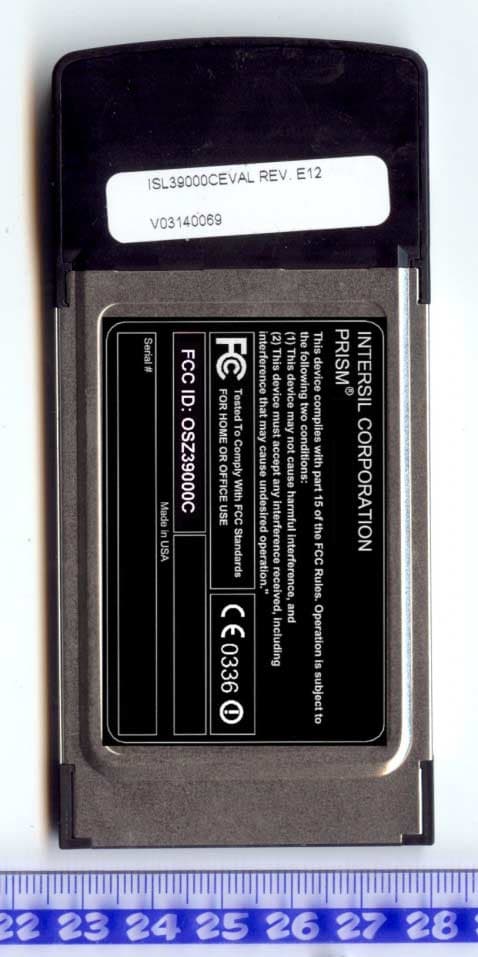
OSZ39000C
Oct 19, 20032.4/5 GHz IEEE 802.11g/a WLAN Cardbus card
Equipment Class
DTS - Digital Transmission System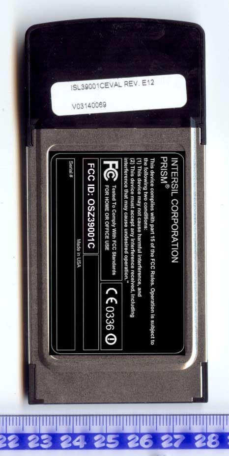
OSZ39001C
Oct 19, 20032.4/5 GHz IEEE 802.11g/a WLAN Cardbus card
Equipment Class
DTS - Digital Transmission System
OSZ39000M1
Aug 20, 20032.4 GHz/5 GHz IEEE 802.11a/g WLAN MiniPCI card
Equipment Class
NII - Unlicensed National Information Infrastructure TX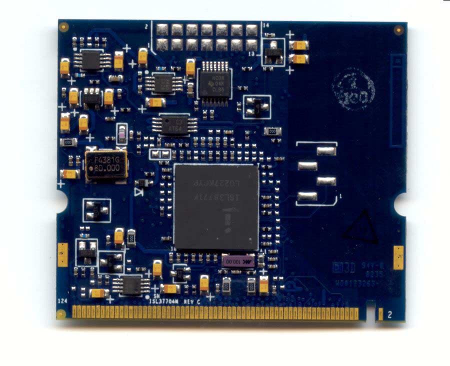
OSZ37704M
May 26, 20035 GHz IEEE 802.11a WLAN MiniPCI card
Equipment Class
NII - Unlicensed National Information Infrastructure TX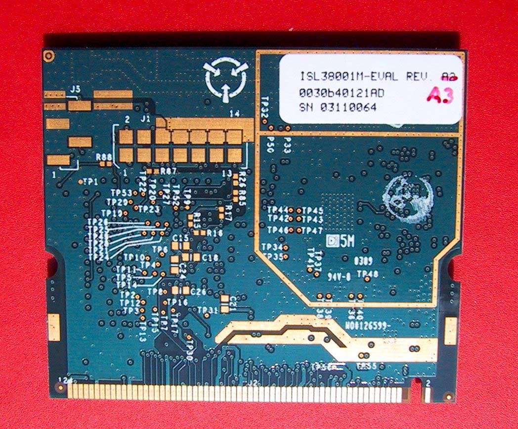
OSZ38001M
May 21, 20032.4 GHz 802.11g WLAN MiniPCI card
Equipment Class
DTS - Digital Transmission System