OSZ39001C2.4/5 GHz IEEE 802.11g/a WLAN Cardbus card
Conexant Systems Inc.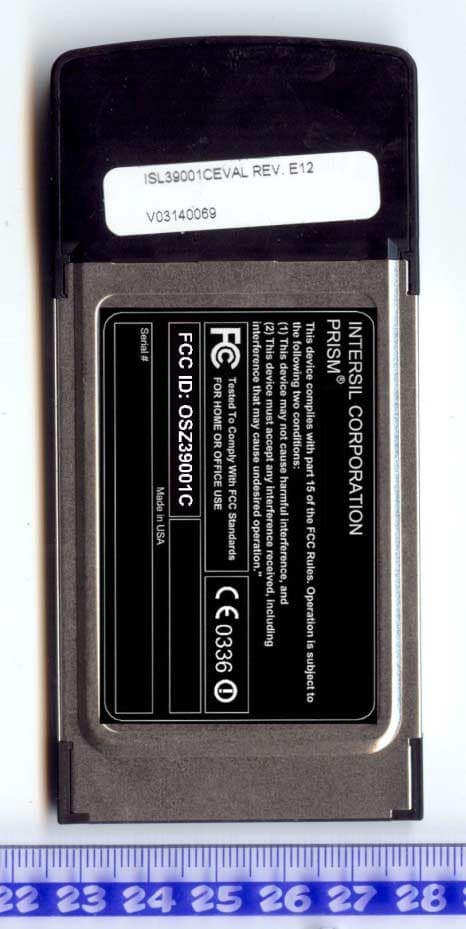
Click to zoom
Application Details
- Equipment Class
- DTS - Digital Transmission System
- Date of Grant
- Oct 19, 2003
- Application Purpose
- Original Equipment
- Date of Application
- Jul 14, 2003
- Equipment Note
- 2.4/5 GHz IEEE 802.11g/a WLAN Cardbus card
- Frequency Range
- 2412.00000000 - 2462.00000000
- Company
- Conexant Systems Inc.
- Country
- United States
Documents & Files
Document Text
Text extracted from the exhibit documents filed with the FCC. Open a document above to read the original.
Users Manual
Preliminary User manual FCC ID: OSZ39001C Page 1 of 10 Intersil ISL39001C IEEE 802.11a/g WLAN Cardbus32 Card User Manual Version 0.1 Preliminary User manual FCC ID: OSZ39001C Page 2 of 10 Table of Contents 0-INTRODUCTION .................................................................................................... 3 1-INSTALLATION PROCEDURE ........................................................................... 3 1.1 INSTALLING THE CARDBUS32 CARD INTO THE HOST PC NOTEBOOK............... 3 1.2 INSTALLING THE SOFTWARE DRIVERS................................................................ 3 1.3 WIRELESS LAN INSTALLATION GUIDE LINES AND AUTHORIZATION FOR USE.7 2-REGULATORY INFORMATION ........................................................................ 7 2.1 FCC INFORMATION TO USER............................................................................. 7 2.2 FCC GUIDELINES FOR HUMAN EXPOSURE........................................................ 7 2.3 FCC ELECTRONIC EMISSION NOTICES.............................................................. 7 2.4 FCC RADIO FREQUENCY INTERFERENCE STATEMENT..................................... 8 2.5 EXPORT RESTRICTIONS....................................................................................... 8 2.6 EUROPE - EU DECLARATION OF CONFORMITY................................................. 9 3-TECHNICAL SPECIFICATIONS....................................................................... 10 Preliminary User manual FCC ID: OSZ39001C Page 3 of 10 0-Introduction The Intersil ISL39001C WLAN NIC is a complete wireless high speed Network Interface Card (NIC). It conforms to the IEEE 802.11g and IEEE 802.11a protocol and operates in the 2.45 GHz and 5150- 5350MHz frequency bands. It provides a complete reference design evaluation platform of hardware and software to system providers or integrators requiring wireless data communications capability and is ideal for integration into computer platforms. • Fully compliant with the IEEE 802.11g and IEEE 802.11a WLAN standards • FCC Certified Under Part 15 (pending) to Operate in the 2.45 GHz and 5150-5350MHz Bands • Support for 54, 48, 36, 24, 18, 12, 9, and 6 Mbps OFDM, 11 and 5.5 Mbps CCK and legacy 2 and 1 Mbps data rates • Driver Supports Microsoft Windows ® 98/SE, ME, XP and 2000 (SR1) 1-Installation procedure 1.1 Installing the Cardbus32 card into the host PC Notebook a-Turn Host PC off, then insert Cardbus card into Cardbus slot of notebook Host PC. CAUTION: 1-- This assembly is designed to operate with a supply voltage of 3.3V in laptop computers supporting the CARDBUS32 standard. 2-- Do not force engagement of the card in the CARDBUS32 slot. It is mechanically designed to prevent improper insertion. 1.2 Installing the software drivers a-Start windows b-When windows detects new hardware and asks for drivers, point to directory where the Intersil driver is located (for example floppy drive, cdrom , harddisk) to install. c-after drivers are installed, restart windows d-the Intersil WLAN icon will appear in system tray on the bottom right of the screen (see yellow arrow in fig. 01) fig, 01: Intersil WLAN icon Preliminary User manual FCC ID: OSZ39001C Page 4 of 10 e-double click the Intersil WLAN icon to open the WLAN settings, the following window will appear (see fig.02) fig, 02: Intersil WLAN settings window f-click on configuration tab and select which type of network is required (access point or Peer-to-peer mode), see fig. 03. fig, 03: WLAN network type setting window Preliminary User manual FCC ID: OSZ39001C Page 5 of 10 g-select what TX rate is required (default setting is fully automatic) see fig. 04. fig, 04: WLAN tx rate setting window h-select what encryption type is required, 64 or 128 bit WEP (default setting is disabled) see fig. 05. fig, 05: WLAN encryption rate setting window Preliminary User manual FCC ID: OSZ39001C Page 6 of 10 i-click on the status tab to see the connection status (fig.06). fig, 06: WLAN network status j-click on the about tab to see the software drivers versions and MAC address (fig.07). fig, 07: WLAN driver and MAC addres information Preliminary User manual FCC ID: OSZ39001C Page 7 of 10 1.3 Wireless LAN installation guide lines and Authorization for use Installation and use of this Wireless LAN device must be in strict accordance with the instructions included in the user documentation provided with the product. Any changes or modifications made to this device that are not expressly approved by Intersil may void the user’s authority to operate the equipment. Intersil is not responsible for any radio or television interference caused by unauthorized modification of this device, or the substitution or attachment of connecting cables and equipment other than specified. It is the responsibility of the user to correct any interference caused by such unauthorized modification, substitution or attachment. Intersil and its authorized resellers or distributors will assume no liability for any damage or violation of government regulations arising from failing to comply with these guidelines. The use of Wireless LAN devices may be restricted in some situations or environments for example: * On board of airplanes, or * In an explosive environment, or * In case the interference risk to other devices or services is perceived or identified as harmful. In case the policy regarding the use of Wireless LAN devices in specific organizations or environments (e.g. airports, hospitals, chemical/oil/gas industrial plants, private buildings etc.) is not clear, please first verify authorization to use these devices prior to operating the equipment. 2-Regulatory information 2.1 FCC Information to User This product does not contain any user serviceable components and is to be used with approved antennas only. Any product changes or modifications will invalidate all applicable regulatory certifications and approvals 2.2 FCC Guidelines for Human Exposure SAR (Specific Absorption…
Text truncated - open the document above for the full version.
Cover Letter(s)
TNO Electronic Products & Services (EPS) B.V. Nederlandse Organisatie voor toegepast-natuurwetenschappelijk onderzoek / Netherlands Organisation for Applied Scientific Research Smidshornerweg 18 P.O. Box 15 9822 ZG Niekerk The Netherlands www.tno.nl T +31 594 505005 F +31 594 504804 E [email protected] Subject Cover letter Date June 8, 2003 Our reference 03K0811 Your reference - Page 1 of 1 Our General Terms and Conditions, as filed at the Chamber of Commerce in Groningen, are applicable to all orders given to TNO Electronic Products & Services (EPS) B.V. TNO Electronic Products & Services (EPS) B.V. is registered at the Chamber of Commerce in Groningen with no. 27247331. Return address: P.O. Box 15, 9822 ZG Niekerk, The Netherlands Office of Engineering and Technology Laboratory Federal Communications Commission 7435 Oakland Mills Road Columbia, MD 21046-1609 U.S.A. Dear Mr./Ms., On behalf of our customer Intersil Corporation, we hereby would like to apply for FCC certification of the following device: FCC ID : OSZ39001C Brand : Intersil Model number : ISL39001C Description : 2.4/5 GHz IEEE 802.11g/a WLAN Cardbus card The following PDF files (exhibits) are electronically submitted: 1. Cover letter containing the request for FCC certification 2. Request for confidentiality 3. Test report(s) in conformity with 47 CFR Part 15 4. Bill of materials 5. Circuit diagram 6. Block diagram 7. Operational description 8. Interior photographs 9. Exterior photographs 10. Test setup photographs 11. SAR test report 12. Authorization letter 13. User manual 14. Label information Best regards, TNO Electronic Products & Services (EPS) B.V. P.A.J.M. Robben, B.Sc.E.E. Marketing Manager
Cover Letter(s)
TNO Electronic Products & Services (EPS) B.V. Nederlandse Organisatie voor toegepast-natuurwetenschappelijk onderzoek / Netherlands Organisation for Applied Scientific Research Smidshornerweg 18 P.O. Box 15 9822 ZG Niekerk The Netherlands www.tno.nl T +31 594 505005 F +31 594 504804 E [email protected] Subject Request for confidentiality Date June 8, 2003 Our reference 03K0811b Your reference - Page 1 of 1 Our General Terms and Conditions, as filed at the Chamber of Commerce in Groningen, are applicable to all orders given to TNO Electronic Products & Services (EPS) B.V. TNO Electronic Products & Services (EPS) B.V. is registered at the Chamber of Commerce in Groningen with no. 27247331. Return address: P.O. Box 15, 9822 ZG Niekerk, The Netherlands Office of Engineering and Technology Laboratory Federal Communications Commission 7435 Oakland Mills Road Columbia, MD 21046-1609 U.S.A. Dear Mr./Ms., Pursuant to section 0.457 of the FCC rules we herewith request the following exhibits, related to this application for FCC ID: OSZ39001C, to be withheld from public inspection and to be kept confidential. The contents of these exhibits may not be disclosed to other parties than Intersil Corporation and TNO Electronic Products & Services (EPS) B.V.: 1. Bill of materials 2. Circuit diagram 3. Operational description 4. Block diagram The reason for this request for confidentiality is that the information contained in the exhibits as listed above has been classified as company confidential. Disclosure of any portion of this information to other parties would cause substantial competitive harm. Best regards, TNO Electronic Products & Services (EPS) B.V. P.A.J.M. Robben, B.Sc.E.E. Marketing Manager
Cover Letter(s)
www.intersil.com ING Bank: 65.02.63.049 Swift code: INGBNL2A VAT / BRW: NL8039.66.659.B.01 Chamber of Commerce Utrecht: 30139807 Date 10 June 2003 Your reference -- Our reference 2003-mansup-585e Subject Agent authorization letter for FCC ID: OSZ39001C To whom it may concern To whom it may concern, This letter confirms the agreement that; TNO Electronic Products & Services (EPS) B.V. Smidshornerweg 18 9822 TL Niekerk The Netherlands is authorized as an agent for Company Intersil Corp. The Netherlands Address, City Rembrandtlaan 1a, Bilthoven Country The Netherlands Phone number +31 30 2296060 Fax number +31 30 2296061 and is authorized to sign application forms and act on behalf of Intersil Corp. The Netherlands and is authorized to receive and exchange data between Intersil Corp. The Netherlands and European/non-European national authorities regarding the -certification of- and/or -arranging type approvals for the following product: Intersil model ISL39001C WLAN Cardbus Card with FCC ID: OSZ39001C This authorization will expire on December, 2003 or upon earlier written notice from Intersil Corp. The Netherlands. Yours sincerely, Derick Sariredjo ( [email protected] ) Intersil Corp. The Netherlands ( www.intersil.com ) Rembrandtlaan 1a, 3723 BG Bilthoven, The Netherlands Phone: +31.30.225.9742 Fax: +31.30.229.6061
External Photos
FCC ID: OSZ39001C Page 1 of 3 External photographs of Description: 2.4 GHz / 5 GHz Dual band WLAN Cardbus Card FCC ID: OSZ39001C Brand name: Intersil Model number: ISL39001C FCC ID: OSZ39001C Page 2 of 3 ISL39001C Front exterior FCC ID: OSZ39001C Page 3 of 3 ISL39001C back exterior
ID Label/Location Info
FCC ID: OSZ39001C Page 1 of 4 FCC and CE Label info of Description: 2.4 GHz / 5GHz dual band WLAN Cardbus Card FCC ID: OSZ39001C Brand name: Intersil Model number: ISL39001C FCC ID: OSZ39001C Page 2 of 4 ISL39001C FCC and CE Label Label material: Tamper evident 0.002" polyester. This material is durable, tamper proof and legible. Tamper proof: If the label is removed after 48 hours (time for the adhesive to cure) it will separate which will leave label material on the attached surface that it was removed from. This label material will spell out the word "VOID". The label will also show the word "VOID" where the label material was pulled away. The end result is the word " VOID " on both the mating surface and label, leaving both unusable. FCC ID: OSZ39001C Page 3 of 4 ISL39001C Front label on Cover set FCC ID: OSZ39001C Page 4 of 4 ISL39001C FCC and CE Back label on Cover set
Internal Photos
FCC ID: OSZ39001CPage 1 of 4 Internal photographs of Description: 2.4 GHz / 5 GHz WLAN Cardbus Card FCC ID: OSZ39001C Brand name: Intersil Model number: ISL39001C FCC ID: OSZ39001CPage 2 of 4 ISL39001C PCB front with shield FCC ID: OSZ39001CPage 3 of 4 ISL39001C PCB front without shield FCC ID: OSZ39001CPage 4 of 4 ISL39001C PCB rear
RF Exposure Info
ISL39001C Prism Duette PCMCIA Card Model No.: ISL39001C Tested For Intersil Corporation Rembrandtlaan 1a 3723 BG Bilthoven P.O. Box 343 3720 AH Bilthoven The Netherlands In Accordance With SAR (Specific Absorption Rate) Requirements using guidelines established in IEEE C95.1-1991, FCC OET Bulletin 65 (Supplement C), Industry Canada RSS-102(Issue 1) and ACA Radiocommunications (Electromagnetic Radiation – Human Exposure) Amendment Standard 2000 (No. 1) UltraTech's File No.: ITS-007-SAR This Test report is Issued under the Authority of Tri M. Luu, Professional Engineer, Vice President of Engineering UltraTech Group of Labs Date: June 25, 2003 Report Prepared by: JaeWook Choi Tested by: JaeWook Choi Issued Date: June 24, 2003 Test Dates: June 18, 2003 ~ June 21, 2003 The results in this Test Report apply only to the sample(s) tested, which has been randomly selected. UltraTech 3000 Bristol Circle, Oakville, Ontario, Canada, L6H 6G4 Telephone (905) 829-1570 Facsimile (905) 829-8050 Website: www.ultratech-labs.com Email: [email protected] SPECIFIC ABSORPTION RATE (SAR) Page 1 IEEE C95.1-1991, FCC OET Bulletin 65 (Supplement C), Industry Canada RSS-102(Issue 1) and ACA Radiocommunications (Electromagnetic Radiation – Human Exposure) Amendment Standard 2000 (No. 1) ISL39001C Prism Duette PCMCIA Card M/N: ISL39001C TABLE OF CONTENTS EXHIBIT 1. INTRODUCTION................................................................................................................................................4 1.1. SCOPE...............................................................................................................................................................................4 1.2. REFERENCES...................................................................................................................................................................4 EXHIBIT 2. PERFORMANCE ASSESSMENT.....................................................................................................................5 2.1. CLIENT AND MANUFACTURER INFORMATION......................................................................................................5 2.2. DEVICE UNDER TEST (D.U.T.) DESCRIPTION..............................................................................................................5 2.3. LIST OF D.U.T.’S ACCESSORIES:.................................................................................................................................. 6 2.4. SPECIAL CHANGES ON THE D.U.T.’S HARDWARE/SOFTWARE FOR TESTING PURPOSES.............................6 2.5. ANCILLARY EQUIPMENT.............................................................................................................................................6 2.6. GENERAL TEST CONFIGURATIONS...........................................................................................................................6 2.6.1. Equipment Configuration...........................................................................................................................................6 2.6.2. Exercising Equipment.................................................................................................................................................6 2.7. SPECIFIC OPERATING CONDITIONS......................................................................................................................................6 2.8. BLOCK DIAGRAM OF TEST SETUP.............................................................................................................................7 EXHIBIT 3. SUMMARY OF TEST RESULTS......................................................................................................................8 3.1. LOCATION OF TESTS.....................................................................................................................................................8 3.2. APPLICABILITY & SUMMARY OF SAR RESULTS.....................................................................................................8 EXHIBIT 4. MEASUREMENTS, EXAMINATIONS & TEST DATA................................................................................9 4.1. TEST SETUP.....................................................................................................................................................................9 4.2. PHOTOGRAPH OF D.U.T. AND ALL ACCESORIES................................................................................................................10 4.3. PHOTOGRAPHS OF D.U.T. POSITION........................................................................................................................15 4.3.1. Body Configuration..................................................................................................................................................15 4.4. MAXIMUM PEAK SPATIAL-AVERAGE SAR........................................................................................................................19 4.4.1. Maximum Peak Spatial-average SAR Data..............................................................................................................19 4.4.2. Maximum Peak Spatial-Average SAR Location.......................................................................................................19 4.5. SAR MEASUREMENT DATA..............................................................................................................................................20 4.5.1. Body Configuration Result.......................................................................................................................................20 4.5.1.1. 802.11g mode (ISM-2.4 band).................................................................................................................................................20 4.5.1.2. 802.11a mode (UNII band).....................................................................................…
Text truncated - open the document above for the full version.
RF Exposure Info
SPECIFIC ABSORPTION RATE (SAR) Page 40 IEEE C95.1-1991, FCC OET Bulletin 65 (Supplement C), Industry Canada RSS-102(Issue 1) and ACA Radiocommunications (Electromagnetic Radiation – Human Exposure) Amendment Standard 2000 (No. 1) ISL39001C Prism Duette PCMCIA Card M/N: ISL39001C 5.7. SAR MEASUREMENT SYSTEM VERIFICATION 5.7.1. Standard Source A half-wave dipole is positioned below the bottom of the phantom and centered with its axis parallel to the longest side of the phantom. The distance between the liquid filled phantom bottom surface and the center of the dipole axis, s, is chosen as specified IEEE 1528 at the specific test frequency (i.e. 15 mm at 835 MHz). A low loss and low dielectric constant spacer is used to establish the correct distance between the top surface of the dipole and the bottom surface of the phantom. 5.7.2. Standard Source Input Power Measurement The system validation is performed as shown below or in Figure 7.1 in IEEE 1528. ULTRATECH GROUP OF LABS File #: ITS-007-SAR 3000 Bristol Circle, Oakville, Ontario, Canada L6H 6G4 June 25, 2003 Tel. #: 905-829-1570, Fax. #: 905-829-8050, Email: [email protected], Website: http://www.ultratech-labs.com • Assessed by ITI (UK) Competent Body, NVLAP (USA) Accreditation Body & ACA/AUSTEL (Australia), VCCI (Japan) • Accredited by Industry Canada (Canada) under ACC-LAB (Europe/Canada MRA and APEC/Canada MRA) • Recognized/Listed by FCC (USA ) • All test results contained in this engineering test report are traceable to National Institute of Standards and Technology (NIST) SPECIFIC ABSORPTION RATE (SAR) Page 41 IEEE C95.1-1991, FCC OET Bulletin 65 (Supplement C), Industry Canada RSS-102(Issue 1) and ACA Radiocommunications (Electromagnetic Radiation – Human Exposure) Amendment Standard 2000 (No. 1) ISL39001C Prism Duette PCMCIA Card M/N: ISL39001C First the power meter PM1 (including attenuator Att1) is connected to the cable to measure the forward power at the location of the dipole connector (X). The signal generator is adjusted for the desired forward power at the dipole connector (taking into account the attenuation of Att1) as read by power meter PM2. After connecting the cable to the dipole, the signal generator is readjusted for the same reading at power meter PM2. If the signal generator does not allow adjustment in 0.01dB steps, the remaining difference at PM2 must be taken into consideration. PM3 records the reflected power from the dipole to ensure that the value is not changed from the previous value. The reflected power was verified to be at least 20dB below the forward power. 5.7.3. System Validation Procedure A complete 1g-averaged SAR measurement is performed. The measured 1g-averaged SAR value is normalized to a forward power of 1W to a half-wave dipole and compared with the reference SAR value for the reference dipole and flat phantom shown in columns 2 and 3 of Table 7.1 in IEEE 1528. ULTRATECH GROUP OF LABS File #: ITS-007-SAR 3000 Bristol Circle, Oakville, Ontario, Canada L6H 6G4 June 25, 2003 Tel. #: 905-829-1570, Fax. #: 905-829-8050, Email: [email protected], Website: http://www.ultratech-labs.com • Assessed by ITI (UK) Competent Body, NVLAP (USA) Accreditation Body & ACA/AUSTEL (Australia), VCCI (Japan) • Accredited by Industry Canada (Canada) under ACC-LAB (Europe/Canada MRA and APEC/Canada MRA) • Recognized/Listed by FCC (USA ) • All test results contained in this engineering test report are traceable to National Institute of Standards and Technology (NIST) SPECIFIC ABSORPTION RATE (SAR) Page 42 IEEE C95.1-1991, FCC OET Bulletin 65 (Supplement C), Industry Canada RSS-102(Issue 1) and ACA Radiocommunications (Electromagnetic Radiation – Human Exposure) Amendment Standard 2000 (No. 1) ISL39001C Prism Duette PCMCIA Card M/N: ISL39001C 5.8. POWER MEASUREMENT Whenever possible, a conducted power measurement is performed. To accomplish this, we utilize a fully charged battery, a calibrated power meter and a cable adapter provided by the manufacturer. The data of the cable and related circuit losses are also provided by the manufacturer. The power measurement is then performed across the operational band and the channel with the highest output power is recorded. Power measurement is performed before and after the SAR to verify if the battery was delivering full power at the time of testing. A difference in output power would determine a need for battery replacement and to repeat the SAR test. mW Power Meter D.U.T. Figure 5.8. Measured Power + Cable and Switching Mechanism Loss ULTRATECH GROUP OF LABS File #: ITS-007-SAR 3000 Bristol Circle, Oakville, Ontario, Canada L6H 6G4 June 25, 2003 Tel. #: 905-829-1570, Fax. #: 905-829-8050, Email: [email protected], Website: http://www.ultratech-labs.com • Assessed by ITI (UK) Competent Body, NVLAP (USA) Accreditation Body & ACA/AUSTEL (Australia), VCCI (Japan) • Accredited by Industry Canada (Canada) under ACC-LAB (Europe/Canada MRA and APEC/Canada MRA) • Recognized/Listed by FCC (USA ) • All test results contained in this engineering test report are traceable to National Institute of Standards and Technology (NIST) SPECIFIC ABSORPTION RATE (SAR) Page 43 IEEE C95.1-1991, FCC OET Bulletin 65 (Supplement C), Industry Canada RSS-102(Issue 1) and ACA Radiocommunications (Electromagnetic Radiation – Human Exposure) Amendment Standard 2000 (No. 1) ISL39001C Prism Duette PCMCIA Card M/N: ISL39001C 5.9. POSITIONING OF D.U.T. The clear SAM phantom shell have been previously marked with a highly visible grid with a defined centre line, so it can easily be seen through the liquid simulated tissue. In the case of testing a cellular phone, this line is connecting the ear channel with the corner of the lips. The D.U.T. is then placed by centering the speaker with the ear channel and the center of the radio width with the corner of the mouth. For HAND HELD devices (push-to-talk), or any other type of wireless transmitters postioned in front of the face, the D.U.T. will b…
Text truncated - open the document above for the full version.
RF Exposure Info
ISL39001C Prism Duette PCMCIA Card Model No.: ISL39001C Tested For Intersil Corporation Rembrandtlaan 1a 3723 BG Bilthoven P.O. Box 343 3720 AH Bilthoven The Netherlands In Accordance With SAR (Specific Absorption Rate) Requirements using guidelines established in IEEE C95.1-1991, FCC OET Bulletin 65 (Supplement C), Industry Canada RSS-102(Issue 1) and ACA Radiocommunications (Electromagnetic Radiation – Human Exposure) Amendment Standard 2000 (No. 1) UltraTech's File No.: ITS-007-SAR This Test report is Issued under the Authority of Tri M. Luu, Professional Engineer, Vice President of Engineering UltraTech Group of Labs Date: June 25, 2003 Report Prepared by: JaeWook Choi Tested by: JaeWook Choi Issued Date: June 24, 2003 Test Dates: June 18, 2003 ~ June 21, 2003 The results in this Test Report apply only to the sample(s) tested, which has been randomly selected. UltraTech 3000 Bristol Circle, Oakville, Ontario, Canada, L6H 6G4 Telephone (905) 829-1570 Facsimile (905) 829-8050 Website: www.ultratech-labs.com Email: [email protected] SPECIFIC ABSORPTION RATE (SAR) Page 1 IEEE C95.1-1991, FCC OET Bulletin 65 (Supplement C), Industry Canada RSS-102(Issue 1) and ACA Radiocommunications (Electromagnetic Radiation – Human Exposure) Amendment Standard 2000 (No. 1) ISL39001C Prism Duette PCMCIA Card M/N: ISL39001C TABLE OF CONTENTS EXHIBIT 1. INTRODUCTION................................................................................................................................................4 1.1. SCOPE...............................................................................................................................................................................4 1.2. REFERENCES...................................................................................................................................................................4 EXHIBIT 2. PERFORMANCE ASSESSMENT.....................................................................................................................5 2.1. CLIENT AND MANUFACTURER INFORMATION......................................................................................................5 2.2. DEVICE UNDER TEST (D.U.T.) DESCRIPTION..............................................................................................................5 2.3. LIST OF D.U.T.’S ACCESSORIES:.................................................................................................................................. 6 2.4. SPECIAL CHANGES ON THE D.U.T.’S HARDWARE/SOFTWARE FOR TESTING PURPOSES.............................6 2.5. ANCILLARY EQUIPMENT.............................................................................................................................................6 2.6. GENERAL TEST CONFIGURATIONS...........................................................................................................................6 2.6.1. Equipment Configuration...........................................................................................................................................6 2.6.2. Exercising Equipment.................................................................................................................................................6 2.7. SPECIFIC OPERATING CONDITIONS......................................................................................................................................6 2.8. BLOCK DIAGRAM OF TEST SETUP.............................................................................................................................7 EXHIBIT 3. SUMMARY OF TEST RESULTS......................................................................................................................8 3.1. LOCATION OF TESTS.....................................................................................................................................................8 3.2. APPLICABILITY & SUMMARY OF SAR RESULTS.....................................................................................................8 EXHIBIT 4. MEASUREMENTS, EXAMINATIONS & TEST DATA................................................................................9 4.1. TEST SETUP.....................................................................................................................................................................9 4.2. PHOTOGRAPH OF D.U.T. AND ALL ACCESORIES................................................................................................................10 4.3. PHOTOGRAPHS OF D.U.T. POSITION........................................................................................................................15 4.3.1. Body Configuration..................................................................................................................................................15 4.4. MAXIMUM PEAK SPATIAL-AVERAGE SAR........................................................................................................................18 4.4.1. Maximum Peak Spatial-average SAR Data..............................................................................................................18 4.4.2. Maximum Peak Spatial-Average SAR Location.......................................................................................................18 4.5. SAR MEASUREMENT DATA..............................................................................................................................................19 4.5.1. Body Configuration Result.......................................................................................................................................19 4.5.1.1. 802.11g mode (ISM-2.4 band)..............…
Text truncated - open the document above for the full version.
Contact Information
Applicant
Derick Sariredjo
Technical Contact
TNO Electronic Products & Services (EPS) B.V.Pieter Robben
[email protected]011 31 594 505005
Smidshornerweg 18 · Niekerk · Netherlands
Non-Technical Contact
TNO Electronic Products & Services (EPS) B.V.Pieter Robben
[email protected]011 31 594 505005
Test Firm
TUV Rheinland Nederland B.V.Ties E. T Koning
Technical Specifications
| # | Rule Parts | Frequency Range | Power Output |
|---|---|---|---|
| 1 | 15C | 2.41 GHz - 2.46 GHz | 77.60 mW |
Other Applications from Conexant Systems Inc.
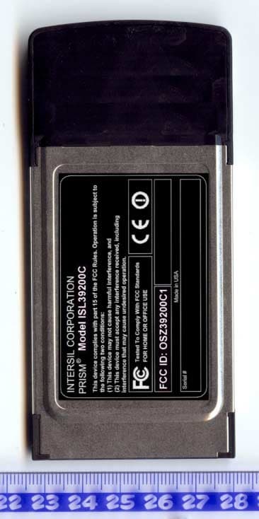
OSZ39200C1
Dec 08, 20032.4/5 GHz IEEE 802.11g/a WLAN Cardbus card
Equipment Class
NII - Unlicensed National Information Infrastructure TX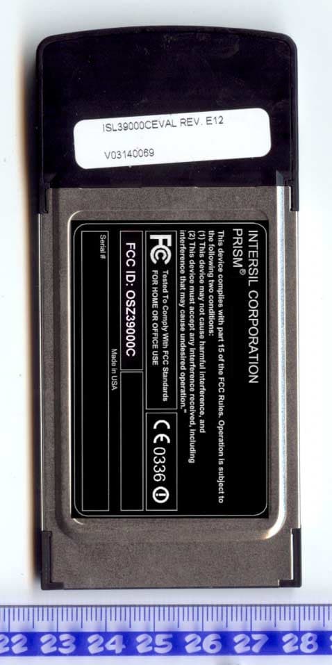
OSZ39000C
Oct 19, 20032.4/5 GHz IEEE 802.11g/a WLAN Cardbus card
Equipment Class
DTS - Digital Transmission System
OSZ39000M1
Aug 20, 20032.4 GHz/5 GHz IEEE 802.11a/g WLAN MiniPCI card
Equipment Class
NII - Unlicensed National Information Infrastructure TX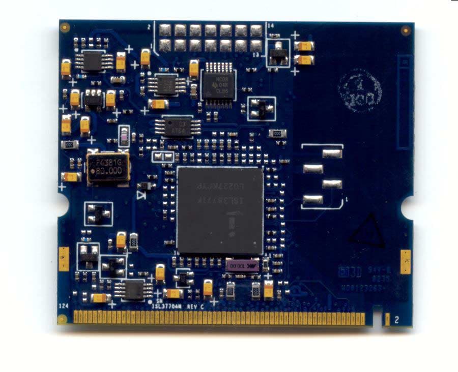
OSZ37704M
May 26, 20035 GHz IEEE 802.11a WLAN MiniPCI card
Equipment Class
NII - Unlicensed National Information Infrastructure TX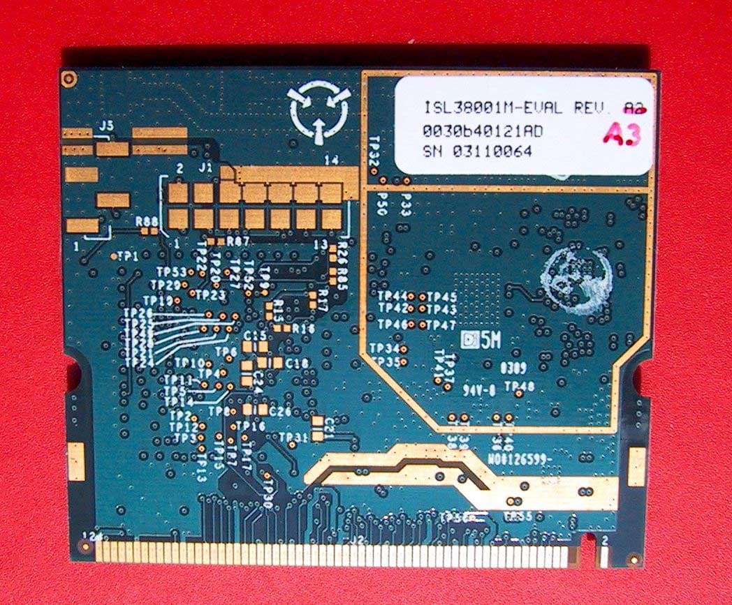
OSZ38001M
May 21, 20032.4 GHz 802.11g WLAN MiniPCI card
Equipment Class
DTS - Digital Transmission System