OSZ36356A1Access Point
Conexant Systems Inc.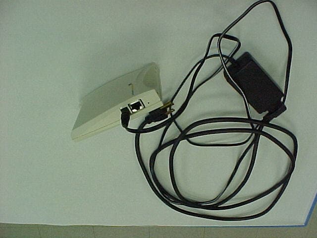
Click to zoom
Application Details
- Equipment Class
- DSS - Part 15 Spread Spectrum Transmitter
- Date of Grant
- Aug 08, 2001
- Application Purpose
- Original Equipment
- Date of Application
- Aug 08, 2001
- Equipment Note
- Access Point
- Frequency Range
- 2412.00000000 - 2462.00000000
- Company
- Conexant Systems Inc.
- Country
- United States
Documents & Files
Document Text
Text extracted from the exhibit documents filed with the FCC. Open a document above to read the original.
Users Manual
User Manual 11 Mbps Wireless LAN Access Point Document version: preliminary 3 Document number: 555004.doc Copyright © 2001 Intersil. All rights reserved. 2 preliminary 3 Trademarks and copyright Copyright © 2001 Intersil. The publisher reserves the right to revise this publication and to make changes to any or all parts of this manual at any time, without obligation to notify any person or entity of such revisions or changes. No part of this publication may be reproduced, stored in a retrieval system, or transmitted in any form or by any means, whether electronic, mechanical, photocopying, recording, or otherwise without the prior written permission of the publisher. AirLock, APCenter, ASBF Connect and KickStart are trademarks of Intersil. Other product and company names are registered trademarks or trademarks of their respective holders. Safety This equipment is designed with utmost care for the safety of those who install and use it. However, special attention must be paid to the dangers of electric shock and static electricity when working with electronic equipment. All guidelines of this manual and of the computer manufacturer must therefore be followed at all times to ensure the safe use of the equipment. Important Notice This device is a 2.4 GHz low power RF device intended for home and office use in all EU member states except in France where restrictive use applies. Please refer to ‘Regulatory notes and statements’ on page 43 in this manual for further details. 555004.doc 3 Contents Contents 1Getting started . . . . . . . . . . . . . . . . . . . . . . . . . . . . . . . . . . .7 1.1Introduction . . . . . . . . . . . . . . . . . . . . . . . . . . . . . . . . . . . . . . . . . . . . . . 7 1.2Contents of this manual . . . . . . . . . . . . . . . . . . . . . . . . . . . . . . . . . . . . . 8 1.3Where to implement a wireless LAN . . . . . . . . . . . . . . . . . . . . . . . . . . . 8 1.4Adding Access Points to your (network) environment . . . . . . . . . . . . . . 9 1.4.1Creating a wireless network . . . . . . . . . . . . . . . . . . . . . . . . . . . . . . . . . . 9 1.4.2Extending a wired network with one or more Access Points . . . . . . . . 10 1.4.3Connecting an Access Point directly to a computer . . . . . . . . . . . . . . . 11 2Installing the Access Point . . . . . . . . . . . . . . . . . . . . . . . .13 2.1Introduction . . . . . . . . . . . . . . . . . . . . . . . . . . . . . . . . . . . . . . . . . . . . . 13 2.2Access Point environment . . . . . . . . . . . . . . . . . . . . . . . . . . . . . . . . . . 13 2.3Physical installation of the Access Point . . . . . . . . . . . . . . . . . . . . . . . 13 2.4Desktop mount installation . . . . . . . . . . . . . . . . . . . . . . . . . . . . . . . . . . 14 2.5Wall mount installation . . . . . . . . . . . . . . . . . . . . . . . . . . . . . . . . . . . . . 15 2.6Connecting the Access Point . . . . . . . . . . . . . . . . . . . . . . . . . . . . . . . . 16 2.6.1Power adapter . . . . . . . . . . . . . . . . . . . . . . . . . . . . . . . . . . . . . . . . . . . 17 2.6.2UTP port . . . . . . . . . . . . . . . . . . . . . . . . . . . . . . . . . . . . . . . . . . . . . . . . 17 2.7LEDs . . . . . . . . . . . . . . . . . . . . . . . . . . . . . . . . . . . . . . . . . . . . . . . . . . 18 2.8Unlocking the Access Point . . . . . . . . . . . . . . . . . . . . . . . . . . . . . . . . . 18 2.8.1Unlocking the Access Point to reconfigure . . . . . . . . . . . . . . . . . . . . . . 18 2.8.2Resetting to the default factory setting . . . . . . . . . . . . . . . . . . . . . . . . . 19 3Configuring the Access Point . . . . . . . . . . . . . . . . . . . . .21 3.1Introduction . . . . . . . . . . . . . . . . . . . . . . . . . . . . . . . . . . . . . . . . . . . . . 21 3.2When to configure the Access Point . . . . . . . . . . . . . . . . . . . . . . . . . . 21 4 preliminary 3 Contents 3.3Starting the Web Interface . . . . . . . . . . . . . . . . . . . . . . . . . . . . . . . . . . .22 3.3.1Installing KickStart . . . . . . . . . . . . . . . . . . . . . . . . . . . . . . . . . . . . . . . . .22 3.3.2Launch KickStart . . . . . . . . . . . . . . . . . . . . . . . . . . . . . . . . . . . . . . . . . .23 3.3.3Select wireless ethernet device . . . . . . . . . . . . . . . . . . . . . . . . . . . . . . .23 3.3.4Device data . . . . . . . . . . . . . . . . . . . . . . . . . . . . . . . . . . . . . . . . . . . . . .24 3.3.5Scanning and rescanning for devices . . . . . . . . . . . . . . . . . . . . . . . . . .24 3.3.6IP settings . . . . . . . . . . . . . . . . . . . . . . . . . . . . . . . . . . . . . . . . . . . . . . .25 3.3.7Static IP settings . . . . . . . . . . . . . . . . . . . . . . . . . . . . . . . . . . . . . . . . . .26 3.3.8IP settings . . . . . . . . . . . . . . . . . . . . . . . . . . . . . . . . . . . . . . . . . . . . . . .27 3.3.9Changing IP settings . . . . . . . . . . . . . . . . . . . . . . . . . . . . . . . . . . . . . . .27 3.3.10Ready to start the Web Interface . . . . . . . . . . . . . . . . . . . . . . . . . . . . . .28 3.3.11Web Interface is launched . . . . . . . . . . . . . . . . . . . . . . . . . . . . . . . . . . .28 3.4Launching Web Interface manually . . . . . . . . . . . . . . . . . . . . . . . . . . . .29 3.5Contents of Web Interface . . . . . . . . . . . . . . . . . . . . . . . . . . . . . . . . . . .29 3.5.1Settings Summary . . . . . . . . . . . . . . . . . . . . . . . . . . . . . . . . . . . . . . . . .29 3.5.2Wireless Settings . . . . . . . . . . . . . . . . . . . . . . . . . . . . . . . . . . . . . . . . . .30 3.5.3Security against unauthorized network access . . . . . . . . . . . . . . . . . . .31 3.5.4To add a a client to the exception list . . . . . . . . . . . . . . . . . . . . . . . . . .32 3.5.5To delete a client from the exception list . . . . . . . . . . . . . . . . . . . . . . . .33 3.5.6Security against eavesdropping . . . . . . . . . . . . . . . . . . . . . . . . . . . . . .34 3.5.7Change WEP password . . . . . . . . . . . …
Text truncated - open the document above for the full version.
Cover Letter(s)
www.intersil.com ING Bank: 65.02.63.049 Swift code: INGBNL2A VAT / BRW: NL8039.66.659.B.01 Chamber of Commerce Utrecht: 30139807 Date 31 July 2001 Your reference -- Our reference Mansup/ds/2001_111 Subject Request for Non disclosure for FCC ID’s OSZ36356A1 and OSZ36356A2 FCC TCB Curtis-Straus LLC Attention: Certification Manager 527 Great Road Littleton, Massachusetts United States of America telephone: (978) 486-8880 fax: (978) 486-8828 Dear FCC TCB, Persuant to 47 CFR Section 0.459, Intersil Corporation hereby requests non disclosure and confidential treatment of the following materials submitted in support of FCC certification application for FCC ID’s OSZ36356A1 and OSZ36356A2: a. Schematic diagrams b. Operational description c. Bill of Material d. PCB layout Above materials contain trade secrets, proprietary and technical information which would customarily be guarded from competitors under 47 CFR section 0.457(d)(2). Disclosure or publication of any portion of this company confidential material to other parties could cause substantial competitive harm and provide unjustified benefits for competitors. Intersil Corporation understands that pursuant to 47 CFR section 0.457(d)(1)(ii) disclosure of the applicant and all accompanying documentation will not be made before the date of the grant. Sincerely yours, Derick Sariredjo Intersil Corp., The Netherlands Manufacturing Engineering Telephone: +31 30 225 97 42 email: [email protected]
External Photos
Intersil Corporation 2.4 WLAN Access Point FCC ID#: OSZ36356A1 Front Cover of WLAN Intersil Corporation 2.4 WLAN Access Point FCC ID#: OSZ36356A1 Back Cover of WLAN with FCC ID Label showing location of FCC Label. Note: PDF File ... ISL 36356A1 FCC label.pdf ... of this filing contains a close-up photo of the FCC Label to be used on this product. Intersil Corporation 2.4 WLAN Access Point FCC ID#: OSZ36356A1 Side Cover with Power Connection showing power cord attached.
ID Label/Location Info
FCC ID: OSZ36356A1 Page 1 of 5 FCC label information Description: 2.4 GHz WLAN Access Point FCC ID: OSZ36356A1 Brand name: Intersil Model numbers: ISL36356A HAP ISL36356A NAP ISL36356A TAP FCC ID: OSZ36356A1 Page 2 of 5 OSZ36356A1 FCC labels Brand: Intersil Model: ISL36356A HAP FCC ID: OSZ36356A1 This device complies with part 15 of the FCC Rules. Operation is subject to the following two conditions: (1) This device may not cause harmful interference, and (2) This device must accept any interference received, including interference that may cause undesired operation. Canada xxxxxxxxxx fig. 1: AP Housing 1 (HAP) Brand: Intersil Model: ISL36356A NAP FCC ID: OSZ36356A1 This device complies with part 15 of the FCC Rules. Operation is subject to the following two conditions: (1) This device may not cause harmful interference, and (2) This device must accept any interference received, including interference that may cause undesired operation. Canada xxxxxxxxxx fig. 2: AP Housing 2 (NAP) Brand: Intersil Model: ISL36356 TAP FCC ID: OSZ36356A1 This device complies with part 15 of the FCC Rules. Operation is subject to the following two conditions: (1) This device may not cause harmful interference, and (2) This device must accept any interference received, including interference that may cause undesired operation. Canada xxxxxxxxxx fig. 3: AP Housing 3 (TAP) FCC ID: OSZ36356A1 Page 3 of 5 OSZ36356A1 FCC label on Housing 1 (HAP) FCC ID: OSZ36356A1 Page 4 of 5 OSZ36356A1 FCC label on Housing 2 (NAP) FCC ID: OSZ36356A1 Page 5 of 5 OSZ36356A1 FCC label on Housing 3 (TAP)
Internal Photos
Intersil Corporation 2.4 WLAN Access Point FCC ID#: OSZ36356A1 PCB showing Reset Switch, Ethernet Connection and Power Connection. Intersil Corporation 2.4 WLAN Access Point FCC ID#: OSZ36356A1 Open for Inspection. Intersil Corporation 2.4 WLAN Access Point FCC ID#: OSZ36356A1 Close-up of Antenna – One of Two. Intersil Corporation 2.4 WLAN Access Point FCC ID#: OSZ36356A1 Close-up of PCB. Intersil Corporation 2.4 WLAN Access Point FCC ID#: OSZ36356A1 PCB Flip Side showing Shielded RF Section. Intersil Corporation 2.4 WLAN Access Point FCC ID#: OSZ36356A1 PCB showing RF Section with Shielding Removed.
RF Exposure Info
Page 1 of 2 _____________________________________________________________________________ W66 N220 Commerce Court, Cedarburg, Wisconsin 53012 • 262-375-4400 • FAX 262-375-4248 Email: [email protected] http://www.lsr.com/ FCC ID: OSZ36356A1, OSZ36356A2 Maximum Permissible Exposure Calculations The effective radiated power for this worst case emission is based on the worst case conducted power and the specified directive and power gains of the dipole antennas contained within the equipment under test. The worst case conducted power from the conducted emissions measurements is 16.3 dBm and the specified antenna gain is 2.1 dBi. The effective radiated power at the antenna aperture is: EIRPdBmdBidBmP t 4.181.23.16=+= The expected power density at a 20 centimeter distance is: () () 22 2 3 10 4.18 2 6.137 10204 10 10 4m mW m W mW r W rW dBm t = × ⋅ == − − π π Re-normalizing this power density on a per square centimeter basis: () 22 24 2 76.13 10 6.137 cm W cm m m mW rW μ =⋅= − The limit for Maximum Permissible Exposure (MPE) given in Table 1 of §1.1310 is given as () 222 max 6.1657 1500 5.2483 1500 )( cm W mW cmMHz MHz mW cmMHz MHzf rW μ = − = − = The base-station uses a Time-Division-Duplex Protocol where the transmitter has a constant duty factor of 50%. Section 2.1091 allows for time averaging of the transmit power for the purposes of the MPE calculations. This fact would reduce the average power to one-half the constantly transmitting value: Page 2 of 2 _____________________________________________________________________________ W66 N220 Commerce Court, Cedarburg, Wisconsin 53012 • 262-375-4400 • FAX 262-375-4248 Email: [email protected] http://www.lsr.com/ () 2 88.6 cm W rW μ = Since: ()() 2 max 2 6.165788.6 cm W rW cm W rW μμ =<= Therefore, the device in question meets the MPE requirmement.
Test Report
W66 N220 Commerce Court, Cedarburg, Wisconsin 53012 • 262-375-4400 • FAX 262-375-4248 Email: [email protected] http://www.lsr.com/ .......... . . . . . . . . . . LS Research Inc. Intersil Access Point: Appendix D to Report Number 301270A1-TX AP ISL 36356 FCC ID: OSZ36356A1, OSZ36356A2 Part 15.247 Type Acceptance, Conducted Measurements prepared for Intersil Revision 1.0 Page 2 of 43 _______________________________________________________________________________________FCC ID: OSZ36356A1 W66 N220 Commerce Court, Cedarburg, Wisconsin 53012 • 262-375-4400 • FAX 262-375-4248 Email: [email protected] http://www.lsr.com/ Table of Contents I. Project Information...............................................................................................................................................3 II. Declaration of Compliance – 15.247 Measurement Summary..........................................................................5 A. Part 15.247 (a)(2) Minimum Emission 6 dB Bandwidth...............................................................................5 B. Part 15.247 (b) (1) Maximum Conducted Emission Output Power..............................................................5 C. Part 15.247 (c) Minimum Relative Spurious Power Spectral Density Level................................................5 D. Part 15.247 (d) Maximum Power Spectral Density.......................................................................................6 III. FCC Conducted Measurements.........................................................................................................................7 A. Part 15.247....................................................................................................................................................7 1. 15.247 (a) (2) Emission 6 dB Bandwidth......................................................................................................7 2. 15.247 (b) (1) Output Power.......................................................................................................................15 3. 15.247 (b) (3) Effective Radiated Power.....................................................................................................22 4. 15.247 (c) Spurious Modulation Products...................................................................................................22 5. 15.247 (d) Power Spectral Density..............................................................................................................33 IV. Critical Equipment List...................................................................................................................................43 V. Equipment Uncertainties.................................................................................................................................43 Page 3 of 43 _______________________________________________________________________________________FCC ID: OSZ36356A1 W66 N220 Commerce Court, Cedarburg, Wisconsin 53012 • 262-375-4400 • FAX 262-375-4248 Email: [email protected] http://www.lsr.com/ Intersil Access Point I. Project Information Project: Intersil Access Point Intersil Contact: Company: Intersil Corporation. Full Name: Bartow Willingham Title: System Engineer Bus: (321)-729-4955 FAX: (321)-724-7094 E-mail: mailto:[email protected] LS Research Contact: Bill Steinike, Operations Manager Brian Petted, Vice President of Engineering Voice: 262-375-4400 Fax: 262-375-4248 Email: [email protected] Report Date: 8/2/01 Revision: 1.0 Proposal #: Proposal File: Intersil Job Number: Page 4 of 43 _______________________________________________________________________________________FCC ID: OSZ36356A1 W66 N220 Commerce Court, Cedarburg, Wisconsin 53012 • 262-375-4400 • FAX 262-375-4248 Email: [email protected] http://www.lsr.com/ Signatures: Technical Approval Page 5 of 43 _______________________________________________________________________________________FCC ID: OSZ36356A1 W66 N220 Commerce Court, Cedarburg, Wisconsin 53012 • 262-375-4400 • FAX 262-375-4248 Email: [email protected] http://www.lsr.com/ II. Declaration of Compliance – 15.247 Measurement Summary Presented below is a compliance matrix showing the test conditions, test indications, test limits and test outcomes associated with the part 15.247 conducted tests performed on the Equipment Under Test: Intersil Access Point AP ISL 36356 FCC Conducted Tests: A. Part 15.247 (a)(2) Minimum Emission 6 dB Bandwidth FCC Test Type EUT Test Conditions 15.247 (a) (2)15.247 (a) (2)15.247 (a) (2) LimitIndicationOutcome Channel 1 (2412 MHz), 11 Mbps 500 kHz, min 10.97 MHzPASS Channel 6 (2437 MHz), 1 Mbps 500 kHz, min 10.97 MHzPASS Channel 6 (2437 MHz), 2 Mbps 500 kHz, min 10.97 MHzPASS Channel 6 (2437 MHz), 5.5 Mbps 500 kHz, min 11.97 MHzPASS Channel 6 (2437 MHz), 11 Mbps 500 kHz, min 10.97 MHzPASS Channel 11 (2462MHz), 11 Mbps 500 kHz, min 12.34 MHzPASS B. Part 15.247 (b) (1) Maximum Conducted Emission Output Power FCC Test Type EUT Test Conditions 15.247 (b) (1)15.247 (b) (1)15.247 (b) (1) LimitIndicationOutcome Channel 1 (2412 MHz), 11 Mbps 30 dBm, Max 15.9 dBmPASS Channel 6 (2437 MHz), 1 Mbps 30 dBm, Max 15.9 dBmPASS Channel 6 (2437 MHz), 2 Mbps 30 dBm, Max 15.9 dBmPASS Channel 6 (2437 MHz), 5.5 Mbps 30 dBm, Max 16.3 dBmPASS Channel 6 (2437 MHz), 11 Mbps 30 dBm, Max 16.1 dBmPASS Channel 11 (2462MHz), 11 Mbps 30 dBm, Max 16.1 dBmPASS C. Part 15.247 (c) Minimum Relative Spurious Power Spectral Density Level FCC Test Type EUT Test Conditions 15.247 (c ) 15.247 (c ) 15.247 (c ) LimitIndicationOutcome Channel 11 (2462 MHz), 11 Mbps, Wide Scan 20 dBc, min 50.7 dBcPASS Channel 1 (2412 MHz), 1 Mbps, Band Edge 20 dBc, min 38.1 dBcPASS Channel 1 (2412 MHz), 2 Mbps , Band Edge 20 dBc, min 36.8 dBcPASS Channel 1 (2412 MHz), 5.5 Mbps, Band Edge 20 dBc, min 30.4 dBcPASS Channel 1 (2412 MHz), 11 Mbps, Band Edge 20 dBc, min 33.1 dBcPASS Channel 11 (2462 MHz), 1 Mbps, Band Edge 20 dBc, min 39.6 dBcPASS Channel 11 (2462 MHz), 2 Mbps , Band Edge 20 d…
Text truncated - open the document above for the full version.
Test Report
FCC ID: OSZ36365A1 1 FCC Processing Gain report of: Description: 2.4 GHz WLAN Access point Brand name: Intersil Model numbers: ISL36356A HAP ISL36356A NAP ISL36356A TAP FCC ID: OSZ36356A1 for -channel 1 at 11 Mbps -channel 6 at 1, 2, 5.5 and 11 Mbps -channel 11 at 11 Mbps FCC ID: OSZ36365A1 2 Table of contents Test Configuration: CW Jamming Margin (15.247) (e) .............................................................. 3 Test Procedure ...................................................................................................................... 3 Processing Gain test data.......................................................................................................... 4 Test data for Channel 1 at 11 Mbps ...................................................................................... 4 Test data for Channel 6 at 1 Mbps ........................................................................................ 9 Test data for Channel 6 at 2 Mbps ...................................................................................... 14 Test data for Channel 6 at 5.5 Mbps ................................................................................... 19 Test data for Channel 6 at 11 Mbps .................................................................................... 24 Test data for Channel 11 at 11 Mbps .................................................................................. 29 FCC ID: OSZ36365A1 3 Test Configuration: CW Jamming Margin (15.247) (e) Basic Test Block Diagram Blue = GP IB control interface Red = Ethernet UTP cable Green = RF path Test Procedure The processing gain is measured using the CW jamming margin method. A signal generator producing a CW Jammer signal (J) is stepped in 50 kHz increments across the 10 MHz pass band of the system. At each point the CW Jammer Signal generator level required to produce a Bit Error Rate equivalent to BER = 10E-5 is recorded as the Jammer level (J). The output power of the PRISM ref. transmitter is fixed at –62.0 dBm (which is about 20.0 dB above RX sensitivity threshold) and referred to as Signal (S). The Jammer to Signal ratio (J/S) is then calculated and recorded with 20% of the worst data points discarded. The lowest remaining (J/S) ratio is referred to as Mj and is used to calculate the processing gain (PG) using the following formula: PG = (S/N)o + Mj + Lsys With: Lsys = 2.0 dB and (S/N)o as derived from data sheet of DSSS chipset. Prism TX ref. Radio (S) Prism RX radio under test Test control PC CW Jammer (J) signal RF combiner Test data output RF att FCC ID: OSZ36365A1 4 Processing Gain test data Test data for Channel 1 at 11 Mbps Device under test ISL36356A WLAN Access point Base Band Processor ISL3863 RF Channel 01 (2412 MHz) Bitrate 11 Mbps Signal (S) level -62.0 dBm (S/N)o from ISL3863 Data sheet 17.0 dB Lsys 2.0 dB Mj = (after discarding 20% worst ones) -7.0 dB PG = Mj + (S/N)o + Lsys -7.0 + 17.0 + 2 = 12.0 dB FCC Limit > 10 dB Freq (Hz) PG (dB) J (dBm) 2407000 14.5 -66.5 2407050 14.6 -66.4 2407100 14.7 -66.3 2407150 14.3 -66.7 2407200 14.2 -66.8 2407250 14.1 -66.9 2407300 14 -67 2407350 14.1 -66.9 2407400 13.9 -67.1 2407450 14.2 -66.8 2407500 13.8 -67.2 2407550 13.7 -67.3 2407600 13.6 -67.4 2407650 13.8 -67.2 2407700 13.8 -67.2 2407750 13.8 -67.2 2407800 13.5 -67.5 2407850 13.5 -67.5 2407900 13.2 -67.8 2407950 13.1 -67.9 2408000 13.1 -67.9 2408050 13 -68 2408100 13.2 -67.8 2408150 13.4 -67.6 2408200 13.5 -67.5 2408250 13 -68 2408300 13 -68 2408350 13.2 -67.8 2408400 13.1 -67.9 2408450 13.2 -67.8 FCC ID: OSZ36365A1 5 Freq (Hz) PG (dB) J (dBm) 2408500 12.5 -68.5 2408550 12.8 -68.2 2408600 12.4 -68.6 2408650 12.3 -68.7 2408700 12.2 -68.8 2408750 11.7 -69.3 2408800 11.8 -69.2 2408850 12.6 -68.4 2408900 12 -69 2408950 12.4 -68.6 2409000 12.4 -68.6 2409050 11.9 -69.1 2409100 12 -69 2409150 12.3 -68.7 2409200 12.1 -68.9 2409250 11.9 -69.1 2409300 12.1 -68.9 2409350 12 -69 2409400 11.9 -69.1 2409450 11.4 -69.6 2409500 10.7 -70.3 2409550 11 -70 2409600 11.8 -69.2 2409650 11.8 -69.2 2409700 11.7 -69.3 2409750 11.6 -69.4 2409800 10.9 -70.1 2409850 11 -70 2409900 12.3 -68.7 2409950 10.6 -70.4 2410000 10.7 -70.3 2410050 11.2 -69.8 2410100 11.1 -69.9 2410150 11.5 -69.5 2410200 11.7 -69.3 2410250 12.2 -68.8 2410300 11.9 -69.1 2410350 12 -69 2410400 11.5 -69.5 2410450 11.5 -69.5 2410500 11.6 -69.4 2410550 11.5 -69.5 2410600 11.6 -69.4 2410650 12 -69 2410700 12.1 -68.9 2410750 12.3 -68.7 2410800 12.2 -68.8 2410850 12.3 -68.7 2410900 12.3 -68.7 FCC ID: OSZ36365A1 6 Freq (Hz) PG (dB) J (dBm) 2410950 12.6 -68.4 2411000 12.5 -68.5 2411050 12.3 -68.7 2411100 12.8 -68.2 2411150 12.9 -68.1 2411200 13 -68 2411250 12.9 -68.1 2411300 12.9 -68.1 2411350 12 -69 2411400 12.6 -68.4 2411450 13.1 -67.9 2411500 13.1 -67.9 2411550 12.8 -68.2 2411600 13 -68 2411650 13.2 -67.8 2411700 13.2 -67.8 2411750 12.9 -68.1 2411800 13.4 -67.6 2411850 13.3 -67.7 2411900 13.1 -67.9 2411950 13.3 -67.7 2412000 13.7 -67.3 2412050 13.6 -67.4 2412100 13.7 -67.3 2412150 14.1 -66.9 2412200 13.7 -67.3 2412250 13.7 -67.3 2412300 13.5 -67.5 2412350 14 -67 2412400 13.4 -67.6 2412450 13.7 -67.3 2412500 13.5 -67.5 2412550 13.1 -67.9 2412600 12.7 -68.3 2412650 12.6 -68.4 2412700 12.7 -68.3 2412750 12.7 -68.3 2412800 13.1 -67.9 2412850 12.7 -68.3 2412900 12.4 -68.6 2412950 13.5 -67.5 2413000 13.3 -67.7 2413050 13.3 -67.7 2413100 12.9 -68.1 2413150 12.7 -68.3 2413200 13 -68 2413250 12.4 -68.6 2413300 12.3 -68.7 2413350 12.1 -68.9 FCC ID: OSZ36365A1 7 Freq (Hz) PG (dB) J (dBm) 2413400 11.9 -69.1 2413450 11.7 -69.3 2413500 12 -69 2413550 12.1 -68.9 2413600 12.6 -68.4 2413650 12.6 -68.4 2413700 11.4 -69.6 2413750 12.4 -68.6 2413800 12.7 -68.3 2413850 12.4 -68.6 2413900 12.6 -68.4 2413950 12.5 -68.5 2414000 12.3 -68.7 2414050 12.4 -68.6 2414100 12.4 -68.6 2414150 12.5 -68.5 2414200 12.4 -68.6 2414250 12.2 -68.8 2414300 12 -69 2414350 12.3 -68.7 2414400 12.2 -68.8 2414450 11.9 -69.1 2414500 11.8 -69.2 2414550 11.8 -69.2 2414600 12.1 -68.9 2414650 12.6 -68.4…
Text truncated - open the document above for the full version.
Test Report
. . . . . . . . . . . . . . . . . . . L. S. Compliance, Inc. Compliance Testing of: Access Point A1 Wireless modem Prepared for: Intersil Test Report Number: 301270A1-TX Date(s) of Testing: June, July, 2001 All results of this report relate only to the items that were tested.All results of this report relate only to the items that were tested. This report may not be reproduced, except in full, without written approval of L. S.This report may not be reproduced, except in full, without written approval of L. S. Compliance, Inc.Compliance, Inc. L. S. Compliance, Inc. W66 N220 Commerce Court Cedarburg, Wisconsin 53012 Phone: 262 - 375 - 4400 Fax: 262 - 375 - 4248 L. S. COMPLIANCE, Inc. FCC ID: OSZ36356A1FCC ID: OSZ36356A1 LSC- 301270 AP-A1of 29 1 INDEXINDEX SectionSectionDescriptionDescription PagePage ## Index1 Description of Measurement Facilities2 Signature Page3 2.3Summary of Test Report4 2.4Introduction4 2.5Purpose5 2.6Conducted Emissions5 2.7Radiated Emission Test Setup6 2.8Radiated Emission Test Procedure6 2.9Test Equipment Utilized7 2.10Restricted Bands Affected8 2.11Photos taken of testing9 2.12Conclusions11 2.13Test Equipment List12 Appendices ASample Calculations:13 i.Calculation of Radiated Emissions Limits14 BData Charts15 CGraphs19 DAttachment of Conducted Emissions Report28 L. S. COMPLIANCE, Inc. FCC ID: OSZ36356A1FCC ID: OSZ36356A1 LSC- 301270 AP-A1of 29 2 DESCRIPTION OF MEASUREMENT FACILITIES Site on File with the FCC ID Number: 31040/SIT 1300F2 Industry Canada listed site: IC 3088 “ The site referenced above has been found to comply with the test site criteria found in ANSI C63.4-1992 and 47CFR Section 2.948.” L. S. COMPLIANCE, Inc. FCC ID: OSZ36356A1FCC ID: OSZ36356A1 LSC- 301270 AP-A1of 29 3 SIGNATURE PAGE Testing By:July 25, 2001 Thomas T. Lee, EMC engineerDATE Testing By:July 25, 2001 Kenneth L. Boston PEDATE Prepared by: Approved by July 25, 2001 Kenneth L. Boston, EMC Lab ManagerDate PE #31926 Registered Professional Engineer (State of Wisconsin) L. S. COMPLIANCE, Inc. FCC ID: OSZ36356A1FCC ID: OSZ36356A1 LSC- 301270 AP-A1of 29 4 1.3SUMMARY OF TEST REPORT MANUFACTURER:Intersil MODEL:Access Point A1 SERIAL:pre-production (rev E pcb) DESCRIPTION:Spread spectrum data packet transceiver FREQUENCY RANGE:2400-2483.5 MHz The AP A1 was found to meetmeet the radiated emission specification of Title 47 CFR FCC, Part 15, subpart C. for an intentional radiator The AP A1 was also found to meetmeet the radiated emission specification of Title 47 CFR, FCC Part 15, subpart B for emissions with regards to the receiver and digital sections of the product. This product is a composite device, with the digital sections subject to verification. Therefore this technical report will primary contain data that is pertinent to the certification of the transmitter section of the product. 1.4INTRODUCTION During June, July of 2001, a series of Radiated and Conducted Emissions tests were performed on a sample model of the AP A1, a spread spectrum transceiver module, designed for use as a wireless Modem. These tests were performed using the test procedures outlined in ANSI C63.4-1992 for intentional radiators, and in accordance with the requirements set forth in FCC Part 15.247 for a spread spectrum transmitter. Tests were also performed as outlined in ANSI C63.4-1992 for non-intentional radiators, in order to verify compliance with the limits set forth in part 15.109 for and to allow verification of emissions for the digital section of the product. These tests were performed by Kenneth L. Boston, PE, and Thomas T. Lee of L. S. Compliance, Inc. L. S. COMPLIANCE, Inc. FCC ID: OSZ36356A1FCC ID: OSZ36356A1 LSC- 301270 AP-A1of 29 5 2.5PURPOSE The above mentioned tests were performed in order to determine the compliance of the AP-A1 transceiver with limits contained in various provisions of Title 47 CFR, FCC Part 15, including: 15.20715.247b15.247e 15.20515.247c15.109 15.247a215.247d Various of these tests, including the conducted RF out the antenna port and the jamming margin test are contained in additional sections of the test report that are appended. All radiated emissions tests were performed to measure the emissions in the frequency bands described by the above sections, and to determine whether said emissions are below the limits established by the above sections. These tests were performed in accordance with the procedure described in the American National Standard for methods of measurement of Radio-Noise Emissions from Low-Voltage Electrical and Electronic Equipment in the Range of 9 kHz to 40 GHz (ANSI C63.4-1992). Another document used as reference for the EMI receiver specification was the International Special Committee on Radio Interference (CISPR) number 16-1 (1993). 2.6Conducted (AC Mains) Test and measurements The Conducted Emission tests were performed within an 8 by 10 foot shielded room located at L. S. Compliance, Inc. in Cedarburg, WI. The test item was placed on a wooden table, with a height of 80 cm above the reference ground plane. The test object was spaced 40 cm from the rear wall of the shielded room and further than 80 cm from adjacent walls, and the test object power supply was plugged into a 50 (ohm) 50/250μH Line Impedance Stabilization Network (LISN). The test area and set-up are in accordance with ANSI C63.4-1992, sections 5, 6, and 7. The AC power supply to the LISN was fed into the shielded room via an appropriate broadband EMI filter. The test sample was set to operate on channel 1, in continuous transmit during the measurements, and operation was also checked on the middle and high channels. The wall transformer DC supply normally supplied with the AP A1 was plugged into the LISN, and the sample was set to transmit. In order to properly control the unit, and create a test signal, a 2 meter length interface cable was connected to the device. This cable was routed into a fiberoptic interface, and then connected to a computer via a 10 meter fiberoptic cable. The comp…
Text truncated - open the document above for the full version.
Test Setup Photos
Test Set-up Photos for the Radiated and C…
Text truncated - open the document above for the full version.
Contact Information
Applicant
Derick Sariredjo
Test Firm
LS Research, LLCRyan Urness
Technical Specifications
| # | Rule Parts | Frequency Range | Power Output |
|---|---|---|---|
| 1 | 15C | 2.41 GHz - 2.46 GHz | 70.00 mW |
Other Applications from Conexant Systems Inc.
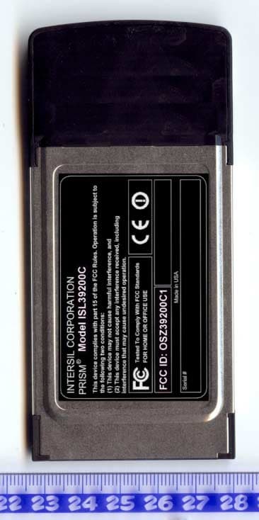
OSZ39200C1
Dec 08, 20032.4/5 GHz IEEE 802.11g/a WLAN Cardbus card
Equipment Class
NII - Unlicensed National Information Infrastructure TX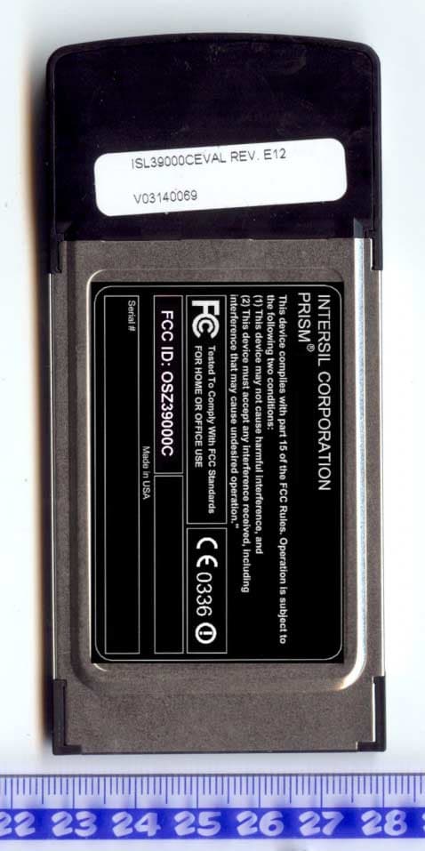
OSZ39000C
Oct 19, 20032.4/5 GHz IEEE 802.11g/a WLAN Cardbus card
Equipment Class
DTS - Digital Transmission System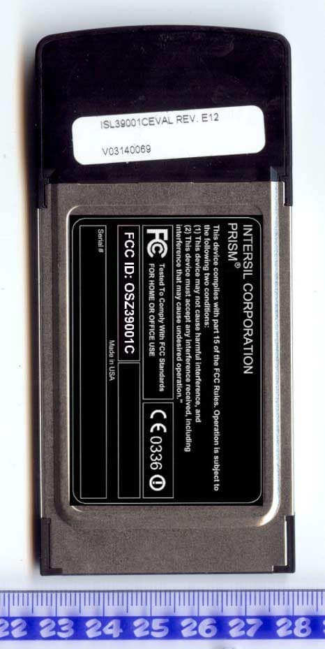
OSZ39001C
Oct 19, 20032.4/5 GHz IEEE 802.11g/a WLAN Cardbus card
Equipment Class
DTS - Digital Transmission System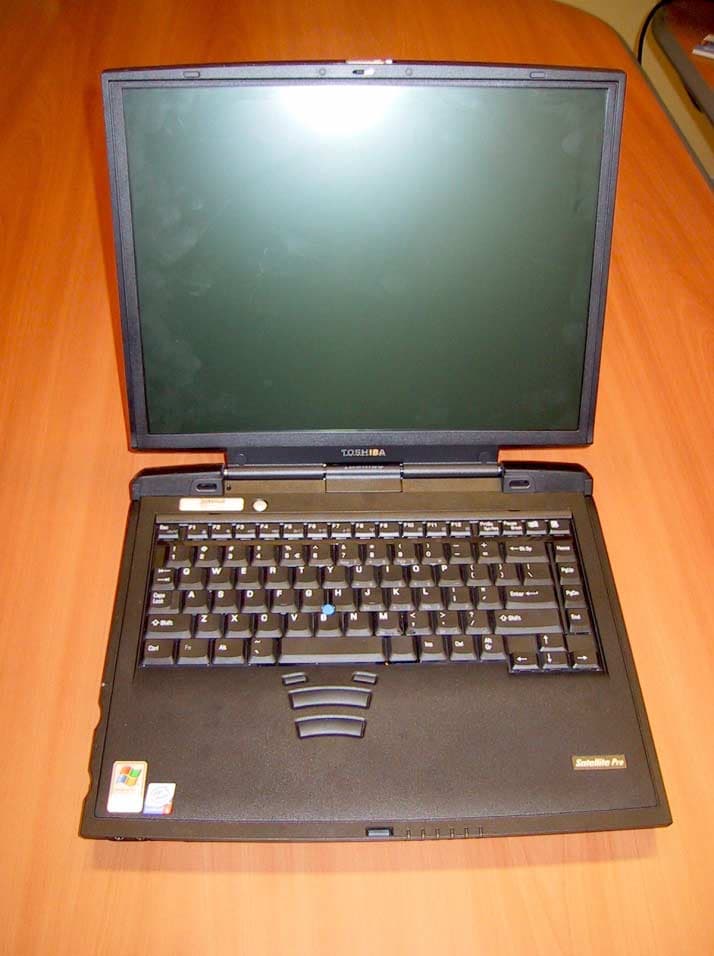
OSZ39000M1
Aug 20, 20032.4 GHz/5 GHz IEEE 802.11a/g WLAN MiniPCI card
Equipment Class
NII - Unlicensed National Information Infrastructure TX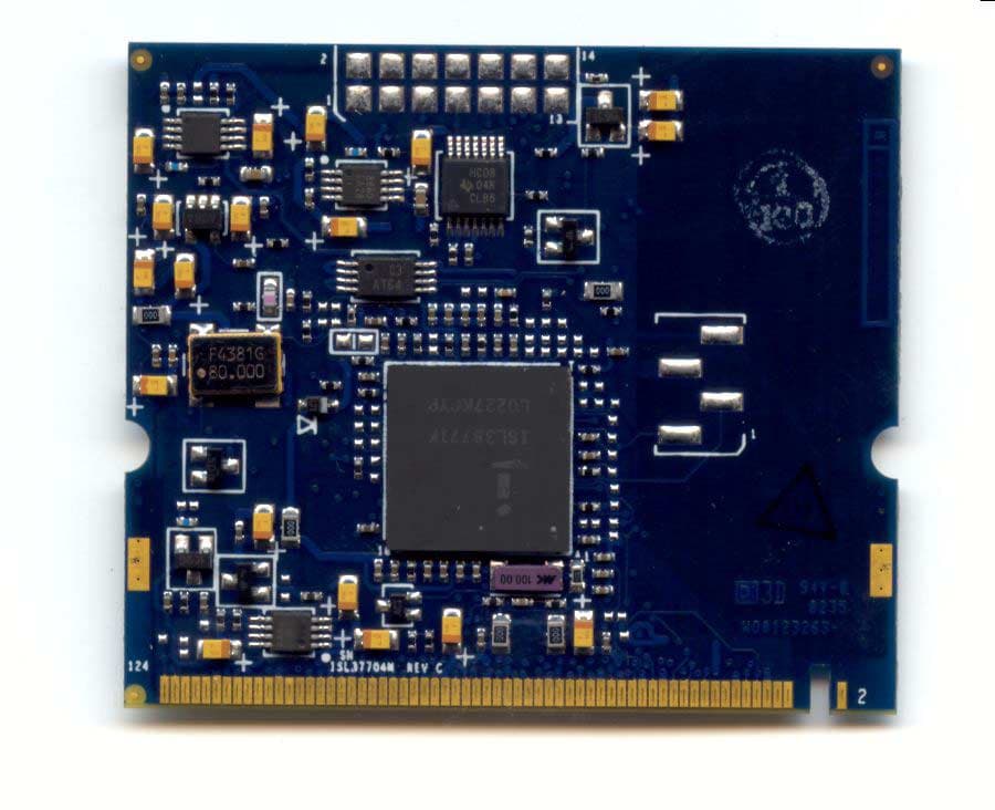
OSZ37704M
May 26, 20035 GHz IEEE 802.11a WLAN MiniPCI card
Equipment Class
NII - Unlicensed National Information Infrastructure TX