OSZ37200M-102.4GHz WLAN miniPCI Card
Conexant Systems Inc.
Click to zoom
Application Details
- Equipment Class
- DTS - Digital Transmission System
- Date of Grant
- Oct 28, 2002
- Application Purpose
- Original Equipment
- Date of Application
- Oct 27, 2002
- Equipment Note
- 2.4GHz WLAN miniPCI Card
- Frequency Range
- 2412.00000000 - 2462.00000000
- Company
- Conexant Systems Inc.
- Country
- United States
Documents & Files
Document Text
Text extracted from the exhibit documents filed with the FCC. Open a document above to read the original.
Users Manual
Preliminary User manual FCC ID: OSZ37200M-10 Page 1 of 10 Intersil ISL37200M-10 MiniPCI WLAN Card User Manual Version 0.1 Preliminary User manual FCC ID: OSZ37200M-10 Page 2 of 10 Table of Contents 0-INTRODUCTION .................................................................................................... 3 1-INSTALLATION ..................................................................................................... 3 1.1 I NSTALLING THE MINIPCI CARD INTO THE HOST PC NOTEBOOK.................... 3 1.2 INSTALLING THE SOFTWARE DRIVERS................................................................ 3 1.3 WIRELESS LAN INSTALLATION GUIDE LINES AND AUTHORIZATION FOR USE.7 2-REGULATORY INFORMATION ........................................................................ 7 2.1 FCC I NFORMATION TO USER............................................................................. 7 2.2 FCC G UIDELINES FOR HUMAN EXPOSURE........................................................ 7 2.3 FCC E LECTRONIC EMISSION NOTICES............................................................. 7 2.4 FCC RADIO FREQUENCY INTERFERENCE STATEMENT.................................... 8 2.5 E XPORT RESTRICTIONS....................................................................................... 8 2.6 E UROPE - EU DECLARATION OF CONFORMITY................................................ 9 3-TECHNICAL SPECIFICATIONS....................................................................... 10 Preliminary User manual FCC ID: OSZ37200M-10 Page 3 of 10 0-Introduction The Intersil ISL37200M WLAN miniPCI card is a complete wireless high speed Network Interface Card (NIC) utilizing the Intersil PRISM® 3 Direct Sequence Spread Spectrum (DSSS) Wireless Transceiver chip set. It provides a complete PRISM 3 reference design evaluation platform of hardware and software to system providers or integrators requiring wireless data communications capability and is ideal for integration into computer platforms. 1- OEM Installation Procedure 1.1 Installing the miniPCI card into the host PC Notebook a-open miniPCI slot cover of host PC Notebook housing b-insert miniPCI card into miniPCI slot c-connect the host PC notebook antennas to the miniPCI card antenna connectors (Hirose type UFL connector) d-close miniPCI slot cover of host PC Notebook housing 1.2 Installing the software drivers a-Start windows b-When windows detects new hardware and asks for drivers, point to directory where the Intersil driver is located (for example floppy drive, cdrom , harddisk) to install. c-after drivers are installed, restart windows d-the Intersil WLAN icon will appear in system tray on the bottom right of the screen (see yellow arrow in fig. 01) fig, 01: Intersil WLAN icon Preliminary User manual FCC ID: OSZ37200M-10 Page 4 of 10 e-double click the Intersil WLAN icon to open the WLAN settings, the following window will appear (see fig.02) fig, 02: Intersil WLAN settings window f-click on configuration tab and select which type of network is required (access point or Peer-to-peer mode), see fig. 03. fig, 03: WLAN network type setting window Preliminary User manual FCC ID: OSZ37200M-10 Page 5 of 10 g-select what TX rate is required (default setting is fully automatic) see fig. 04. fig, 04: WLAN tx rate setting window h-select what encryption type is required, 64 or 128 bit WEP (default setting is disabled) see fig. 05. fig, 05: WLAN encryption rate setting window Preliminary User manual FCC ID: OSZ37200M-10 Page 6 of 10 i-click on the status tab to see the connection status (fig.06). fig, 06: WLAN network status j-click on the about tab to see the software drivers versions and MAC address (fig.07). fig, 07: WLAN driver and MAC addres information Preliminary User manual FCC ID: OSZ37200M-10 Page 7 of 10 1.3 Wireless LAN installation guide lines and Authorization for use Installation and use of this Wireless LAN device must be in strict accordance with the instructions included in the user documentation provided with the product. Any changes or modifications made to this device that are not expressly approved by Intersil may void the user’s authority to operate the equipment. Intersil is not responsible for any radio or television interference caused by unauthorized modification of this device, or the substitution or attachment of connecting cables and equipment other than specified. It is the responsibility of the user to correct any interference caused by such unauthorized modification, substitution or attachment. Intersil and its authorized resellers or distributors will assume no liability for any damage or violation of government regulations arising from failing to comply with these guidelines. The use of Wireless LAN devices may be restricted in some situations or environments for example: * On board of airplanes, or * In an explosive environment, or * In case the interference risk to other devices or services is perceived or identified as harmful. In case the policy regarding the use of Wireless LAN devices in specific organizations or environments (e.g. airports, hospitals, chemical/oil/gas industrial plants, private buildings etc.) is not clear, please first verify authorization to use these devices prior to operating the equipment. 2-Regulatory information 2.1 FCC Information to User This product does not contain any user serviceable components and is to be used with approved antennas only. Any product changes or modifications will invalidate all applicable regulatory certifications and approvals 2.2 FCC Guidelines for Human Exposure Warning: In order to comply with RF exposure limits established in the ANSI C95.1 standards, the user is advised to maintain a distance of at least 20 cm from the antenna of this device while it is in use. 2.3 FCC Electronic Emission Notices This device complies with part 15 of the FCC Rules. Operation is subject to the following two conditions: 1. This device may not cause harmful interference 2. This device must accep…
Text truncated - open the document above for the full version.
Cover Letter(s)
www.intersil.com ING Bank: 65.02.63.049 Swift code: INGBNL2A VAT / BRW: NL8039.66.659.B.01 Chamber of Commerce Utrecht: 30139807 Date 09 September 2002 Your reference -- Our reference Mansup/ds/2002_096 Subject Request for Non disclosure (FCC ID: OSZ37200M-10) Bay Area Compliance Laboratory Corp. TCB dept. 230 Commercial Street Sunnyvale, CA 94085 United States of America telephone: (408) 732-9162 fax: (408) 732-9164 Dear TCB, Persuant to 47 CFR Section 0.459, Intersil Corporation hereby requests non disclosure and confidential treatment of the following materials submitted in support of FCC certification application forFCC ID: OSZ37200M-10: a. Schematic / Circuit diagrams b. Theory of operation c. PCB layout Above materials contain trade secrets, proprietary and technical information which would customarily be guarded from competitors under 47 CFR section 0.457(d)(2). Disclosure or publication of any portion of this company confidential material to other parties could cause substantial competitive harm and provide unjustified benefits for competitors. Intersil Corporation understands that pursuant to 47 CFR section 0.457(d)(1)(ii) disclosure of the applicant and all accompanying documentation will not be made before the date of the grant. Sincerely yours, Derick Sariredjo Intersil Corp. Telephone: +31 30 225 97 42 email: [email protected]
Cover Letter(s)
American Telecommunications Certification Body Inc. 6731 Whittier Ave, McLean, VA 22101 October 28, 2002 RE: FCC ID: OSZ37200M-10 Attention: Derick Sariredjo / Rita Cai I have a few comments on this Application. 1 You have provided the same document for the block diagram and the theory of operation. The request for confidentiality does not include the Block diagram. While the theory of operation is on the list to be confidential, part of the theory of operation is also includes the Block Diagram. Please revise the request for confidentiality to include all pertinent documents. This would be the schematic, the theory of operation the PCB layout/parts list. Parts list. Please also note that the PCB/parts list was not provided even though it is listed as confidential. 2 Page 6 of the report states that correction factors are automatically included in the test receiver. Please verify that all factors used to determine the compliance have been included. Please provide a sample calculation of how your test equipment includes these factors and an explanation of how you insure that all factors have been included. Anwers The receiver corrects the measured levels of emissions automatically with the applicable antenna factor and cable loss. These values are permanently stored into the receiver. The antenna factor and cable loss values are determined at regular calibration intervals as required by our quality system. The receiver performs the calculation as: Input value (dBuV) + ( antenna factor (dB) + cable loss (dB) ) = Measurement value (dBuV/m) The functioning of the test receiver, that is; whether all and the correct factors are being used, are checked at the start of each measurement as required by our quality system. 3 On paged 12-14 of the EMC test report, you show a number of readings that are compared to the wrong limits. Please correct the report to reflect the correct limits. (i.e. 200 MHz to 500MHz are incorrect.) Answers The limits on the pages 12-14 have been corrected. 4 Please note that while there may be a ‘defacto’ ‘peak’ limit for the restricted bands, the average limit must be met. You incorrectly state that the average readings are n/a. Please correct the report to show compliance with both the ‘defacto peak limit’ (74dB) and the average limit of 54dBuV for the restricted bands. Answers All measurements were performed while using a peak detector. Since all measurement values are below the "average" limits, while using the peak detector, the equipment is deemed to comply with these "average" limits. This has been verified in those instances where the peak value was close to the "average" limit and is also reported as such (see note(s) below the various tables). l Page 2October 28, 2002 5 Please note that the requirements of 15.247(c) are a band edge requirement as well as a 15.205 restricted band limit requirement. You must show that the device meets the 20dB band edge requirement at both ends of the allowed spectrum for the device. Tables 14 and 15 are not clear on this issue. Please provide data on the band edges of the device operating at the highest frequency possible for the device as well as the lowest. Alternately, please clearly define which table is the lowest frequency possible in the device and which table is the highest frequency possible. Answer The results with the EUT operating on three channels may be found in section 5.3 of the test reports. The plots were made in max hold mode with the spectrum analyzer continuously sweeping. The EUT was then switched from channel 1 to channel 6 and from channel 6 to channel 11. The plots therefore do incorporate all test data required. The results in tables 14 and 15 are the only results which have to be reported and represent the worst case results with the EUT operating on either channel 1, 6 and 11 (see note below tables). The level of emissions on other frequencies than reported is more than 20 dB below the applicable limit (as stated in table 14 and 15, last row). 6 You have not stated if the maximum power measured is a conducted antenna terminal measurement or if it is power derived from radiated measurements. If the power is derived from radiated emissions measurements of the fundamental, please note that this is not simply an e field measurement, but must be calculated power. Please show that you have used the required FCC formula for radiated power measurements i.e. P=(Ed)^2 / 30G). If other methods have been used, please fully describe this method. If the table is conducted antenna terminal measurements, please so indicate. Answer Since conducted RF output power measurements are the ones which should be performed, and while radiated RF output power measurements are the EXCEPTION to the Rules, we did not mention the fact that the test results were obtained while performing conducted measurements. However, this has been corrected in the revised test report. 7 Please note that the 731 form states the power is 89mW, yet the measured power is only 72.4 (see page 18 of your report). Please correct the 731 to state the correct power of the device. Please note the FCC puts actual power on grants, not rated power. Answers Please refer to the attached corrected Form 731. 8 IEEE1528 states, “The system check must be performed using the same liquid as in the compliance test and at a chosen fixed frequency that is within ± 10% of the compliance test mid-band frequency. The system check is performed prior to compliance tests and the result must always be within ± 10% of the target value corresponding to the test frequency and the source used.” The FCC requires that validation be done within 100MHz of the center frequency of the device being tested. Please provide SAR information in accordance with these requirements. (Validation done at 1800MHz, device operates at 2400Mhz). Refer to page 17 of your SAR report and the plots of SAR data. Answer Question 8 to 11, please refer to the attached revised SAR test report. l Page 3October 2…
Text truncated - open the document above for the full version.
Cover Letter(s)
American Telecommunications Certification Body Inc. 6731 Whittier Ave, McLean, VA 22101 October 18, 2002 RE: FCC ID: OSZ37200M-10 Attention: Rita Cai I have a few comments on this Application. 1 Item 10 of the 10-08-02 request for in formation has not been resolved. The FCC has stated that calibration of the probes used in SAR measurement need be calibrated 100MHz of the target frequency. The highest frequency of calibration data for the probe used is 1900MHz, the device center frequency is 2430MHz. Please address this issue. You must resolve this calibration issue of the probe before a grant can be issued. Please re-test the device using a properly calibrated probe. Dennis Ward mailto:[email protected] The items indicated above must be submitted before processing can continue on the above referenced application. Failure to provide the requested information may result in application termination. Correspondence should be considered part of the permanent submission and may be viewed from the Internet after a Grant of Equipment Authorization is issued. Please do not respond to this correspondence using the email reply button. In order for your response to be processed expeditiously, you must submit your documents through the AmericanTCB.com website. Also, please note that partial responses increase processing time and should not be submitted. Any questions about the content of this correspondence should be directed to the sender.
Cover Letter(s)
www.intersil.com ING Bank: 65.02.63.049 Swift code: INGBNL2A VAT / BRW: NL8039.66.659.B.01 Chamber of Commerce Utrecht: 30139807 Date 28 February 2003 Your reference -- Our reference Mansup/ds/2003-295_2 Subject Request for Limited Module approval for FCC ID: OSZ37200M-10 Bay Area Compliance Laboratory Corp TCB dept. 230 Commercial Street Sunnyvale, CA 94085 United States of America telephone: (408) 732-9162 fax: (408) 732-9164 Dear TCB, This letter is to confirm that Intersil Corp. is requesting a “Limited Modular Approval” for the 2.4 GHz IEEE 802.11b WLAN MiniPCI card with FCC ID: OSZ37200M-10. The usage of this wireless device will be limited to the following Notebook PC’s: IBM R30 series. In case any additional information or documents are required, please do not hesitate to contact me. Best regards, Derick Sariredjo Manufacturing Support / Regulatory Office Telephone: +31 30 225 97 42 email: [email protected]
External Photos
FCC ID: OSZ37200M-10Page 1 of 4 External photographs of Description: 2.4 GHz WLAN miniPCI card FCC ID: OSZ37200M-10 Brand name: Intersil Model number: ISL37200M-10 FCC ID: OSZ37200M-10Page 2 of 4 ISL37200M-10 Front PCB with shields and FCC/ETSI label FCC ID: OSZ37200M-10Page 3 of 4 ISL37200M-10 Front PCB without shield FCC ID: OSZ37200M-10Page 4 of 4 ISL37200M-10 Rear PCB
Internal Photos
FCC ID: OSZ37200M-10 Page 1 of 5 Photographs of IBM notebook PC antennas for Description: 2.4 GHz WLAN MiniPCI Card FCC ID: OSZ37200M-10 Brand name: Intersil Model number: ISL37200M-10 FCC ID: OSZ37200M-10 Page 2 of 5 Overview of Host PC of ISL37200M-10 MiniPCI card FCC ID: OSZ37200M-10 Page 3 of 5 Overview of ISL37200M-10 MiniPCI card mounted in host PC with antennas FCC ID: OSZ37200M-10 Page 4 of 5 Inverted F antenna mounted on left side of LCD screen FCC ID: OSZ37200M-10 Page 5 of 5 Slot antenna mounted on right side of LCD screen
Operational Description
FCC ID: OSZ37200M-10 Intersil model ISL37200M-10 Block diagram with Theory of operation TX signal path in Red Arrows Transmitter Path Data bits coming from the miniPCI Host interface (5) are processed by the Base Band Processor MAC (BBP/MAC) ISL3872 (4) on IEEE 802.11b HR protocol level, IQ modulated and then converted to 2.4 GHz RF signal by Direct up/down converter ISL3684 (3) The 2.4GHz RF signal is then amplified by RF Power Amplifier ISL3984 (2) and then finally emitted via the antenna (1). RX signal path in Blue Arrows Receiver path The 2.4GHz RF signal comes in via antennas (1) and low noise amplifier (part of ISL3684) (3) to the Direct up/down converter ISL3684 (3) where it is converted to RX IQ signals. These IQ signals are converted into data bits by the Base Band Processor MAC (BBP/MAC) ISL3872 (4). The data bits are processed by the Base Band Processor MAC (BBP/MAC) ISL3872 (4) on IEEE 802.11b HR protocol level. This MAC controller also provides the miniPCI interface to the Host (5). Antenna 2412-2462MHz (1) ISL3984 RF Power Amplifier 2412-2462MHz (2) ISL3684 Up/down converter 2412-2462MHz Zero IF (3) ISL3872 Base Band Processor/MAC (4) Host interface MiniPCI (5) 44MHz clock oscillator Divide by 2 (part of ISL3684) 2412-2462MHz ISL3084 VCO 4824-4924MHz Antenna 2412-2462MHz (1) ISL3684 Up/down converter 2412-2462MHz Zero IF (3) ISL3872 Base Band Processor/MAC (4) Host interface miniPCI (5) 44MHz clock oscillator Divide by 2 (part of ISL3684) 2412-2462MHz (3) ISL3084 VCO 4824-4924MHz Low Noise Amplifier (part of ISL3684) 2412-2462MHz (3)
RF Exposure Info
RF EXPOSURE According to §15.247(b)(4) and §1.1307(b)(1), systems operating under the provisions of this section shall be operated in a manner that ensures that the public is not exposed to radio frequency energy level in excess of the Commission’s guidelines. According to §1.1310 and §2.1093 RF exposure is calculated. Limits for Maximum Permissive Exposure (MPE) Frequency Range (MHz) Electric Field Strength (V/m) Magnetic Field Strength (A/m) Power Density (mW/cm 2 ) Averaging Time (minute) Limits for General Population/Uncontrolled Exposure 0.3-1.34 614 1.63 *(100) 30 1.34-30 824/f 2.19/f *(180/f 2 ) 30 30-300 27.5 0.073 0.2 30 300-1500 / / f/1500 30 1500-15000 / / 1.0 30 f = frequency in MHz * = Plane-wave equivalent power density MPE Prediction Predication of MPE limit at a given distance Equation from page 18 of OET Bulletin 65, Edition 97-01 S = PG/4πR² Where: S = power density P = power input to antenna G = power gain of the antenna in the direction of interest relative to an isotropic radiator R = distance to the center of radiation of the antenna Maximum peak output power at antenna input terminal: 18.6 (dBm) Maximum peak output power at antenna input terminal: 72.44 (mW) Prediction distance: 20 (cm) Predication frequency: 2400 (MHz) Antenna Gain (typical): 2 (dBi) Maximum antenna gain: 1.58 (numeric) Power density at predication frequency at 20 cm: 0.023 (mW/cm 2 ) MPE limit for uncontrolled exposure at prediction frequency: 1 (mW/cm 2 ) Test Result The predicted power density level at 20cm is 0.023 mW/cm 2 . This is below the uncontrolled exposure limit of 1mW/cm 2 at 2400 MHz. The EUT is used at least 20 cm away from user’s body, it is defined as mobile device.
Test Report
Testing and certification of, consultancy and research concerning, electronic and electric appliances, systems, installations and telecommunication systems TNO Electronic Products & Services (EPS) B.V. P.O. Box 15 9822 ZG Niekerk (NL) Smidshornerweg 18 9822 TL Niekerk (NL) Telephone: +31 594 505005 Telefax: +31 594 504804 E-mail: [email protected] Project number: 02082901.r02.rev2 Page 1 of 39 TEST REPORT OF A 2.4 GHZ LOW POWER RLAN CARD, BRAND INTERSIL, MODEL ISL37200M-10, IN CONFORMITY WITH 47 CFR PART 15 (2001-12-18). FCC listed Industry Canada : : 90828 IC3501 Test specification(s): Description of EUT: Manufacturer: Brand mark: Model: FCC ID: 47 CFR Part 15 (2001-12-18) 2.4 GHz low power RLAN card Intersil Corporation Intersil ISL37200M-10 OSZ37200M-10 Project number: 02082901.r02.rev2 Page 2 of 39 MEASUREMENT/TECHNICAL REPORT Intersil Corporation Model : ISL37200M-10 FCC ID: OSZ37200M-10 November 1, 2002 This report concerns: Original grant/certification Class 2 change Verification Equipment type: Direct Sequence Spread Spectrum Transceiver Deferred grant requested per 47 CFR 0.457(d)(1)(ii) ? Yes No Report prepared by: Name : P.A.J.M. Robben Company name : TNO Electronic Products & Services (EPS) B.V. Address : Smidshornerweg 18 Postal code/city : 9822 ZG Niekerk Mailing address : P.O. Box 15 Postal code/city : 9822 TL Niekerk Country : The Netherlands Telephone number : + 31 594 505 005 Telefax number : + 31 594 504 804 E-mail : [email protected] The data taken for this test and report herein was done in accordance with 47 CFR Part 15 and the measurement procedures of ANSI C63.4-1992. TNO Electronic Products & Services (EPS) B.V. at Niekerk, The Netherlands, certifies that the data is accurate and contains a true representation of the emission profile of the Equipment Under Test (EUT) on the date of the test as noted in the test report. I have reviewed the test report and find it to be an accurate description of the test(s) performed and the EUT so tested. Date: November 1, 2002 Signature: P. de Beer TNO Electronic Products & Services (EPS) B.V. Test specification(s): Description of EUT: Manufacturer: Brand mark: Model: FCC ID: 47 CFR Part 15 (2001-12-18) 2.4 GHz low power RLAN card Intersil Corporation Intersil ISL37200M-10 OSZ37200M-10 Project number: 02082901.r02.rev2 Page 3 of 39 Description of test item Test item : 2.4 GHz low power RLAN card Manufacturer : Intersil Corp., The Netherlands Brand : Intersil Model : ISL37200M-10 Serial numbers : 02100049 Revision : Rev. C3 Receipt number : 1 Receipt date : August 29, 2002 Applicant information Applicant's representative : Mr. D. Sariredjo Company : Intersil Corporation Address : Rembrandtlaan 1a Postal code : 3723 BG City : Bilthoven PO-box : 343 Postal code : 3720AH City : Bilthoven Country : The Netherlands Telephone number : +31 30 2259742 Telefax number : +31 30 2296061 Test(s) performed Location : Niekerk Test(s) started : August 29, 2002 Test(s) completed : September 3, 2002 Purpose of test(s) : Type approval / certification Test specification(s) : 47 CFR Part 15 (2001-12-18) Test engineer : O.H. Hoekstra Report written by : O.H. Hoekstra Project leader : O.H. Hoekstra This report is in conformity with NEN-EN-ISO/IEC 17025: 2000. This report shall not be reproduced, except in full, without the written permission of TNO Electronic Products & Services (EPS) B.V. The test results relate only to the item(s) tested. Test specification(s): Description of EUT: Manufacturer: Brand mark: Model: FCC ID: 47 CFR Part 15 (2001-12-18) 2.4 GHz low power RLAN card Intersil Corporation Intersil ISL37200M-10 OSZ37200M-10 Project number: 02082901.r02.rev2 Page 4 of 39 Table of contents 1 General information................................................................................................................................................................. 5 1.1 Product description. ......................................................................................................................................................... 5 1.2 Related submittal(s) and/or Grant(s). .............................................................................................................................. 5 1.3 Tested system details. ...................................................................................................................................................... 5 1.4 Test methodology. ........................................................................................................................................................... 6 1.5 Test facility. ..................................................................................................................................................................... 6 1.6 Product labeling. .............................................................................................................................................................. 6 1.7 System test configuration. ............................................................................................................................................... 7 1.7.1 Justification.............................................................................................................................................................. 7 1.7.2 EUT exercise software............................................................................................................................................. 7 1.8 Special accessories. ......................................................................................................................................................... 7 1.9 Equipment modifications................................................................................................................................................. 8 1.10 Configuration of the tested system. ................................................................................................................…
Text truncated - open the document above for the full version.
Test Setup Photos
Testing and certification of, consultancy and research concerning, electronic and electric appliances, systems, installations and telecommunication systems 47 CFR PART 15 TEST SETUP PHOTOGRAPHS OF A 2.4 GHZ LOW POWER RLAN CARD, BRAND INTERSIL, TYPE ISL37200M-10. Accredited by FCC listed Industry Canada : : : Dutch Council of Accreditation STERLAB accreditation number L385 90828 IC3501 TNO Electronic Products & Services (EPS) B.V. P.O. Box 15 9822 ZG Niekerk (NL) Smidshornerweg 18 9822 TL Niekerk (NL) Telephone: +31 594 505005 Telefax: +31 594 504804 E-mail: [email protected] Project number: 02082901.p01 Page 1 of 7 Description of EUT: Manufacturer: Brand mark: Type: FCC ID: 2.4 GHz low power RLAN card Intersil Corp., The Netherlands Intersil ISL37200M-10 OSZ37200M-10 Description of test item Test item : 2.4 GHz low power RLAN card Manufacturer : Intersil Corp., The Netherlands Brand : Intersil Type : ISL37200M-10 Serial numbers : 02260003 Revision : Rev. C3 Receipt number : 1 Receipt date : August 29 , 2002 Applicant information Applicant's representative : Mr. D. Sariredjo Company : Intersil Corporation Address : Rembrandtlaan 1a Postal code : 3723 BG City : Bilthoven PO-box : 343 Postal code : 3720AH City : Bilthoven Country : The Netherlands Telephone number : +31 30 2259742 Telefax number : +31 30 2296061 This report is in conformity with NEN-EN-ISO/IEC 17025: 2000. This report shall not be reproduced, except in full, without the written permission of TNO Electronic Products & Services (EPS) B.V. The test results relate only to the item(s) tested. Project number: 02082901.p01 Page 2 of 7 Description of EUT: Manufacturer: Brand mark: Type: FCC ID: 2.4 GHz low power RLAN card Intersil Corp., The Netherlands Intersil ISL37200M-10 OSZ37200M-10 Table of contents 1 Radiated emission test setup...................................................................................................................................................4 1.1 Radiated emission test setup (front)...............................................................................................................................4 1.2 Radiated emission test setup (back)................................................................................................................................5 2 Conducted emission test setup................................................................................................................................................6 2.1 Conducted emission test setup (front)............................................................................................................................6 2.2 Conducted emission test setup (back)............................................................................................................................7 Project number: 02082901.p01 Page 3 of 7 Description of EUT: Manufacturer: Brand mark: Type: FCC ID: 2.4 GHz low power RLAN card Intersil Corp., The Netherlands Intersil ISL37200M-10 OSZ37200M-10 1 Radiated emission test setup. 1.1 Radiated emission test setup (front). Project number: 02082901.p01 Page 4 of 7 Description of EUT: Manufacturer: Brand mark: Type: FCC ID: 2.4 GHz low power RLAN card Intersil Corp., The Netherlands Intersil ISL37200M-10 OSZ37200M-10 1.2 Radiated emission test setup (back). Project number: 02082901.p01 Page 5 of 7 Description of EUT: Manufacturer: Brand mark: Type: FCC ID: 2.4 GHz low power RLAN card Intersil Corp., The Netherlands Intersil ISL37200M-10 OSZ37200M-10 2 Conducted emission test setup. 2.1 Conducted emission test setup (front). Project number: 02082901.p01 Page 6 of 7 Description of EUT: Manufacturer: Brand mark: Type: FCC ID: 2.4 GHz low power RLAN card Intersil Corp., The Netherlands Intersil ISL37200M-10 OSZ37200M-10 2.2 Conducted emission test setup (back). Project number: 02082901.p01 Page 7 of 7
Test Setup Photos
FCC ID: OSZ37200M-10 Page 1 of 5 Photographs of IBM notebook PC antennas for Description: 2.4 GHz WLAN MiniPCI Card FCC ID: OSZ37200M-10 Brand name: Intersil Model number: …
Text truncated - open the document above for the full version.
Contact Information
Applicant
Derick Sariredjo
Technical Contact
TNO Electronic Products & ServicesPieter Robben
[email protected]+31 594 50 5005
Smidshornerweg 18 · Niekerk · Netherlands
Non-Technical Contact
TNO Electronic Products & ServicesPieter Robben
[email protected]+31 594 50 5005
Test Firm
TUV Rheinland Nederland B.V.Ties E. T Koning
Technical Specifications
| # | Rule Parts | Frequency Range | Power Output |
|---|---|---|---|
| 1 | 15C | 2.41 GHz - 2.46 GHz | 72.40 mW |
Other Applications from Conexant Systems Inc.
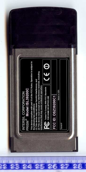
OSZ39200C1
Dec 08, 20032.4/5 GHz IEEE 802.11g/a WLAN Cardbus card
Equipment Class
NII - Unlicensed National Information Infrastructure TX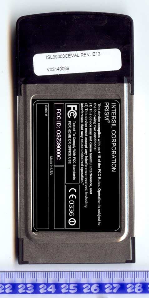
OSZ39000C
Oct 19, 20032.4/5 GHz IEEE 802.11g/a WLAN Cardbus card
Equipment Class
DTS - Digital Transmission System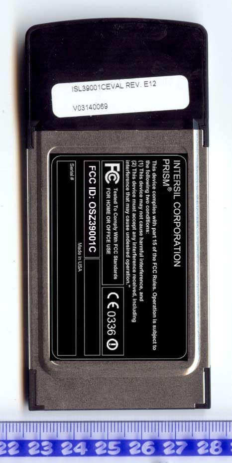
OSZ39001C
Oct 19, 20032.4/5 GHz IEEE 802.11g/a WLAN Cardbus card
Equipment Class
DTS - Digital Transmission System
OSZ39000M1
Aug 20, 20032.4 GHz/5 GHz IEEE 802.11a/g WLAN MiniPCI card
Equipment Class
NII - Unlicensed National Information Infrastructure TX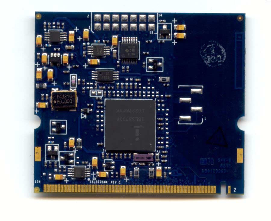
OSZ37704M
May 26, 20035 GHz IEEE 802.11a WLAN MiniPCI card
Equipment Class
NII - Unlicensed National Information Infrastructure TX