OSZ37400M11Mbps Wireless Local Area Network PC Card
Conexant Systems Inc.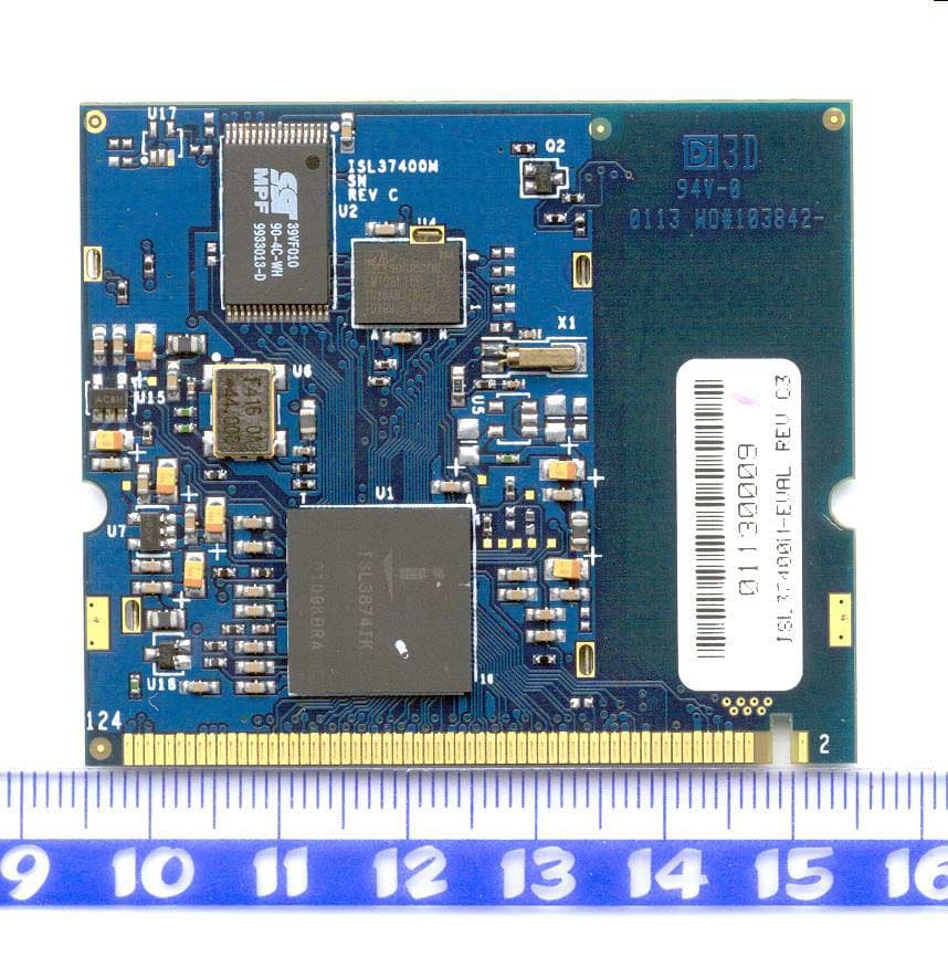
Click to zoom
Application Details
- Equipment Class
- DSS - Part 15 Spread Spectrum Transmitter
- Date of Grant
- Jun 28, 2001
- Application Purpose
- Original Equipment
- Date of Application
- Jun 26, 2001
- Equipment Note
- 11Mbps Wireless Local Area Network PC Card
- Frequency Range
- 2412.00000000 - 2462.00000000
- Company
- Conexant Systems Inc.
- Country
- United States
Documents & Files
Document Text
Text extracted from the exhibit documents filed with the FCC. Open a document above to read the original.
Users Manual
4-1 TM File Number CAUTION: These devices are sensitive to electrostatic discharge; follow proper IC Handling Procedures. 1-888-INTERSIL or 321-724-7143 |Intersil and Design is a trademark of Intersil Americas Inc. Copyright © Intersil Americas Inc. 2001, All Rights Reserved PRELIMINARY ISL37400M-EVAL PRISM 2.5 11Mbps Wireless Local Area Network PC Card The Intersil ISL37400M WLAN PC Card (Note 1) is a complete wireless high speed Network Interface Card (NIC) utilizing the Intersil PRISM® 2.5 Direct Sequence Spread Spectrum Wireless Transceiver chip set. It provides a complete PRISM 2.5 reference design evaluation platform of hardware and software to system providersorintegratorsrequiringwirelessdata communications capability and is ideal for integration into computer platforms. Evaluation kits include two WLAN PC cards designed to Intersil’s PRISM reference design, Microsoft Windows® Driver, Local Area Network evaluation software, PRISM Transmitter Test Utilities (PTTU) software (Note 3) and documentation to get your evaluation started quickly. Supporting the IEEE 802.11 network specification for Direct Sequence Spread Spectrum DSSS signaling, the card is packaged in a PCMCIA Type II extended cover set. The card provides data rates of 1, 2, 5.5 and 11Mbps. Access Points will be available from a number of suppliers, enabling a total wireless network solution Typical operating ranges are shown in Table 2.. Features • FCC Certified Under Part 15 to Operate in 2.4GHz ISM Band (Approval Pending) • Support for 11, 5.5, 2 and 1 Megabit Per Second (Mbps) Data Rates • Supports the lEEE 802.11 Direct Sequence Specification • Driver Supports Microsoft® Windows® 95, 98, 2000, NT, CE and LINUX® • Supports Dual Diversity Antennas • Advanced RAKE Receiver Design with AGC • Provides Wireless Data Communications at Full Ethernet Speed • Designed to Fully Support miniPCI Type 3A Defined Mechanical and Environmental Stress Conditions • Intelligent Power Control, Including Low Power Standby Mode • Complete Reference Design, the ISL37400M is Available to Ensure Minimum Time-to-Market NOTES: 1. Throughout this document, all references to ‘PC Card’, ‘WLAN adapter’, ‘adapter’, or ‘card’ refer to a card assembly conforming to the mechanical size specifications of the miniPCI Type 3A. 2. The range will vary in different operating environments due to effects such as building construction. 3. At present, PTTU supports Windows 95 and 98. An upgrade is in process which will add support for NT. Packaging TABLE 1. TYPICAL OPERATING RANGE(NOTE 2) DATA RATE (Mbps)INDOOR RANGEOUTDOOR RANGE 11120 feet (37 meters)400 feet (122 meters) 5.5200 feet (61 meters)600 feet (183 meters) 2240 feet (73 meters)750 feet (228 meters) 1300 feet (91 meters)1000 feet (305 meters) Ordering Information PART NUMBERDESCRIPTIONCARDS /SET ISL37400M-EVALWLAN Evaluation Kit2 Data SheetJune 2001 Authors: Douglas Kalcik & Ken Diaz le ec o w () to I ar e s ar 4-2 Functional Overview The WLAN PC Card is designed to operate in the 2.4GHz ISM frequency band, channels 1 to 11, as specified by the FCC in the USA. The Card will also operate on channels 12 through 14, where permitted by local regulatory authorities. Radio equipment must be certified in a country prior to use. Refer to Table 3 for a list of countries and agencies that have approved the ISL37400M-EVAL for operation. The Intersil PRISM Chip Set allows for high level integration for reduced size, increased throughput, improved radio performance and faster time to market. The WLAN PC card implements Direct Sequence Spread Spectrum DSSS technology providing superior noise and signal jamming immunity including less severe impact from unintentional radiators such as microwave ovens. The user can connect the PC Card in an ad-hoc peer to peer networking scheme, allowing for instant network setup in any office environment. By using an access point, the wireless LAN can be set up to allow for a greater number of users to interconnect, and to increase the coverage area. With a portal (i.e., Access Point), the wireless LAN can be easily connected into an existing wired LAN, allowing for easy expansion of the service. Compared to the first generation PRISM II chip set, the PRISM 2.5 generation offers: • 3.3V operation for reduced power dissipation • Reduction in current drain for extended battery life • Dual antenna’s for use with Diversity circuits to improved multipath performance • Higher level of chip integration and less peripheral components to reduce material costs • Support of optional IEEE 802.11 Short Preamble for significantly increased data throughput A complete Reference Design for the ISL37400M is availabletoensureminimumtime-to-market.This information contains detailesfor manufacturing a miniPCI WLAN assembly, including Gerber PC board files, an accurate Bill of Material with component sourcing and complete mechanical drawings. Related Literature To learn more about what the IEEE 802.11 is, refer to: • Tech Brief TB337, Intersil Corporation, “A Brief Tutorial on Spread Spectrum and Packet Radio”[1]. For a more detailed description of radio operation, please refer to: • Application Note AN9951, Intersil Corporation, “ISL37400M-EVAL PRISM 2.5 11 Mb miniPCI Wireless LAN Radio Description” [2] The HFA3841 Media Access Controller (MAC) Protocol Handler The ISL3874 MAC/Baseband Processor and its firmware are responsible for running the IEEE 802.11 protocol in the WLAN card. This section describes the features of IEEE 802.11 that are implemented. The functions supported by the STA (station) Firmware are: • CSMA/CA (Carrier Sense Multiple Access with Collision Avoidance) with Random Backoff • WEP Security • Short/Long Preamble with multirate • RTS/CTS Handshake (Ready To Send / Clear To Send) and NAV Management (Network Allocation Vector) • MAC Level Acknowledgments (Media Access Control) • Re-Transmission of Unacknowledged Frames • Duplicate Detection and Rejection • Broadcast and Multicast Frame…
Text truncated - open the document above for the full version.
Cover Letter(s)
www.intersil.com ING Bank: 65.02.63.049 Swift code: INGBNL2A VAT / BRW: NL8039.66.659.B.01 Chamber of Commerce Utrecht: 30139807 Date 25 June 2001 Your reference -- Our reference Mansup/ds/2001-105 Subject Request for FCC certification for FCC ID: OSZ37400M Telefication, Dept. FCC TCB att. mr. M. Jansen Utrechtseweg 310 6812 AR Arnhem P.O. Box 60004 6800 JA Arnhem The Netherlands Dear FCC TCB, We hereby request for FCC certification of the following device: FCC ID OSZ37400M Brand Intersil Model number ISL37400M Description 2.4GHz Low power WLAN MiniPCI card The following pdf files are electronically submitted as attachments. Ref. Description 1 Cover letter with request for FCC Grant 2 Letter with request for non-disclosure 3 Completed FCC form 731 4 FCC test report 5 Processing gain test report 6 Maximum Permissible Exposure (MPE) Engineering Analysis 7 Block diagram with operational description 8 Bill of material 9 Circuit diagram 10 PCB layout 11 Internal and external photographs, incl. FCC label 12 User manual In case any additional information or documents are required, please do not hesitate to contact me directly Best regards, Derick Sariredjo Telephone: +31 30 225 97 42 email: [email protected]
Cover Letter(s)
www.intersil.com ING Bank: 65.02.63.049 Swift code: INGBNL2A VAT / BRW: NL8039.66.659.B.01 Chamber of Commerce Utrecht: 30139807 Date 26 June 2001 Your reference -- Our reference Mansup/ds/2001-107 Subject Request for Limited Modular approval Telefication, Dept. FCC TCB att. mr. M. Jansen Utrechtseweg 310 6812 AR Arnhem P.O. Box 60004 6800 JA Arnhem The Netherlands Dear FCC TCB, We hereby request for Limited Modular approval for the following device: FCC ID OSZ37400M Brand Intersil Model number ISL37400M Description 2.4GHz Low power WLAN MiniPCI card The usage of this radio will be limited to the following IBM Thinkpad notebooks: Model number ThinkPad i series 1200/1300 In case any additional information or documents are required, please do not hesitate to contact me directly Best regards, Derick Sariredjo Telephone: +31 30 225 97 42 Mobile: +31 6 273 28 048 email: [email protected]
Cover Letter(s)
www.intersil.com ING Bank: 65.02.63.049 Swift code: INGBNL2A VAT / BRW: NL8039.66.659.B.01 Chamber of Commerce Utrecht: 30139807 Date 25 June 2001 Your reference -- Our reference Mansup/ds/2001_106 Subject Request for Non disclosure (FCC ID: OSZ37400M) Telefication, Dept. FCC TCB att. mr. M. Jansen Utrechtseweg 310 6812 AR Arnhem P.O. Box 60004 6800 JA Arnhem The Netherlands Dear FCC TCB, Persuant to 47 CFR Section 0.459, Intersil Corporation hereby requests non disclosure and confidential treatment of the following materials submitted in support of FCC certification application for FCC ID: OSZ37400M: a. Schematic diagrams b. Operational description c. Bill of Material d. PCB layout Above materials contain trade secrets, proprietary and technical information which would customarily be guarded from competitors under 47 CFR section 0.457(d)(2). Disclosure or publication of any portion of this company confidential material to other parties could cause substantial competitive harm and provide unjustified benefits for competitors. Intersil Corporation understands that pursuant to 47 CFR section 0.457(d)(1)(ii) disclosure of the applicant and all accompanying documentation will not be made before the date of the grant. Sincerely yours, Derick Sariredjo Intersil Corp. Telephone: +31 30 225 97 42 email: [email protected]
External Photos
FCC ID: OSZ37400M Page 1 of 9 Photographs of Description: 2.4 GHz WLAN MiniPCI Card FCC ID: OSZ37400M Brand name: Intersil Model number: ISL37400M FCC ID: OSZ37400M Page 2 of 9 Overview of Host PC of ISL37400M MiniPCI card FCC ID: OSZ37400M Page 3 of 9 Overview of ISL37400M MiniPCI card mounted in host PC with antennas FCC ID: OSZ37400M Page 4 of 9 ISL3700M MiniPCI card mounted in host PC FCC ID: OSZ37400M Page 5 of 9 ISL37400M MiniPCI card interior front view (digital) FCC ID: OSZ37400M Page 6 of 9 ISL37400M MiniPCI card interior rear view with shields (RF) FCC ID: OSZ37400M Page 7 of 9 ISL37400M MiniPCI card interior rear view without shields (RF) \ FCC ID: OSZ37400M Page 8 of 9 Inverted F antenna FCC ID: OSZ37400M Page 9 of 9 Slot antenna
ID Label/Location Info
FCC ID: OSZ37400M Page 1 of 3 FCC label information Description: 2.4 GHz WLAN MiniPCI Card FCC ID: OSZ37400M Brand name: Intersil Model number: ISL37400M FCC ID: OSZ37400M Page 2 of 3 ISL37400M FCC label FCC ID: OSZ37400M Page 3 of 3 ISL37400M FCC label on cabinet
Internal Photos
FCC ID: OSZ37400M Page 1 of 9 Photographs of Description: 2.4 GHz WLAN MiniPCI Card FCC ID: OSZ37400M Brand name: Intersil Model number: ISL37400M FCC ID: OSZ37400M Page 2 of 9 Overview of Host PC of ISL37400M MiniPCI card FCC ID: OSZ37400M Page 3 of 9 Overview of ISL37400M MiniPCI card mounted in host PC with antennas FCC ID: OSZ37400M Page 4 of 9 ISL3700M MiniPCI card mounted in host PC FCC ID: OSZ37400M Page 5 of 9 ISL37400M MiniPCI card interior front view (digital) FCC ID: OSZ37400M Page 6 of 9 ISL37400M MiniPCI card interior rear view with shields (RF) FCC ID: OSZ37400M Page 7 of 9 ISL37400M MiniPCI card interior rear view without shields (RF) \ FCC ID: OSZ37400M Page 8 of 9 Inverted F antenna FCC ID: OSZ37400M Page 9 of 9 Slot antenna
RF Exposure Info
1 Engineering analysis of a low power DSSS spread spectrum Transceiver, Equipment description: 2.4GHz WLAN MiniPCI Card Brand name: Intersil Model number: ISL37400M FCC ID: OSZ37400M According to requirements of : FCC part 15.247 (b) (4), FCC OET Bulletin 65 “Evaluating Compliance with FCC Guidelines for Human Exposure to Radio frequency Electromagnetic Fields “ and supplements A, B and C. Date: June 15, 2001 Author: D.S. Sariredjo, Intersil Corp. The Netherlands 2 Introduction This engineering analysis was done according to FCC part 15.247 (b) (4) as part of the FCC certification requirements for spread spectrum devices. The measured EIRP values for the lowest, middle and highest TX channel were used for the MPE calculations based on FCC OET Bulletin 65 and supplements A, B, and C. These calculations were done in worst case mode, assuming 100% reflection of incoming radiation, resulting in a potential doubling of predicted field strength and a four-fold increase in (far-field equivalent) power density (S). EIRP S = 4πR 2 (power density without reflection) (2) 2 EIRP S = 4πR 2 (worst case power density with 100% reflection) with R = 20 cm (8 inches) Calculation results Table 1 below shows the Power density (S) results for the lowest, middle and highest TX channel: Measured EIRP (mW) Calculated worst case Power Density S (mW/cm 2 ) Ch 1 Ch 6 Ch 11 Ch 1 Ch 6 Ch 11 66.1 67.6 64.6 0.052 0.053 0.051 Table 1: Power density (S) calculations Conclusion Based on these calculations and using the limits of the general population / uncontrolled environment (which is 1.0 mW/cm 2 at 2.4 GHz), the Intersil low power spread spectrum transceiver does not exceed the MPE requirements set forth in documents above, with a minimum safe distance between antenna and operator of 20 centimeters (8 inches). The equipment therefore fulfills the requirements on power density for general population / uncontrolled exposure and therefore complies with the requirements of FCC Part 15.247(b)(4) and FCC OET Bulletin 65 incl. supplements A, B, and C.
Test Report
284 West Drive, Suite B Melbourne, FL 32904 RUBICOM SYSTEMS, INC. MAY 2001 Rubicom Systems, Inc. THIS REPORT SHALL NOT BE REPRODUCED EXCEPT IN FULL WITHOUT THE WRITTEN APPROVAL OF THE TESTING LABORATORY FCC TEST REPORT INTENTIONAL RADIATOR FOR THE INTERSIL CORP. MODEL ISL 37400M 2.4GHz WIRELESS TRANSMITTER JA-1817 1 FCC TEST REPORT (INTENTIONAL RADIATOR) FOR THE INTERSIL CORP. MODEL ISL 37400M 2.4GHz WIRELESS TRANSMITTER S/N: 0022 Prepared by: __________________________________________________ Joseph G. Barbee Tested by:__________________________________________________ Alex Belardinelli Performed by:Performed for: RUBICOM SYSTEMS, INC.INTERSIL CORP. 284 West Drive, Suite BP.O. Box 883 Melbourne, Florida 32904Melbourne, FL 32902 Received:April 24, 2001 Completed:May 2, 2001 JA-1817 2 TABLE OF CONTENTS Paragraph TitlePage CERTIFICATION .....................................................................................................3 ABSTRACT.............................................................................................................4 1.0INTRODUCTION .....................................................................................................5 1.1Purpose....................................................................................................................5 1.2Requirements ..........................................................................................................5 1.3Unit Under Test Description ....................................................................................7 1.4Summary of Results ................................................................................................8 2.0APPLICABLE DOCUMENTS .................................................................................9 3.0TEST SITE DESCRIPTION...................................................................................10 3.1Environmental Conditions .....................................................................................10 4.0TEST INSTRUMENTATION .................................................................................11 5.0TEST SAMPLE SETUP AND CONFIGURATIONS .............................................12 FIGURE 5.0-1 ........................................................................................................12 6.0PROCEDURES AND RESULTS ..........................................................................14 6.1General ..................................................................................................................14 6.2Power Line Conducted 15.207 ..............................................................................14 6.3Radiated Emissions 15.209/15.205 ......................................................................14 6.3.1 Radiated Emissions (Pre-Scans) ..............................................................14 6.3.2 Radiated Emissions ...................................................................................29 6.3.3 Peak Ambient (EUT Off/Support Equipment On) .....................................29 6.4Operation Within The Bands (2.4GHz-2.4835GHz) 15.204(2)(b)(c)(d) ..............78 6.4.1 6dB Bandwidth 15.247(2) ..........................................................................78 6.4.2 Peak Output Power 15.247(2)(b) ..............................................................86 6.4.3Out of Band Emission 15.247(2)(c) ..........................................................86 6.4.4 Power Spectral Density 15.247(2)(d) ......................................................126 APPENDIX A COMPLIANCE LETTER ...................................................................................140 JA-1817 3 CERTIFICATION Rubicom Systems, Inc. certifies the information obtained in this report was performed consistent with the requirements of ANSI C63.4-1992. The Intersil Corp. Model ISL 37400M, 2.4GHz Wireless Transmitter complies with the requirements of CFR 47 Part 15 for Intentional Radiators as required in Paragraph 15.247(a)(2)(b)(1)(c) and (d). This data was obtained while testing an ISL 37400M Wireless Transmitter, s/n: 0022, furnished by Intersil Corp. Any modifications to the unit as tested may invalidate the data and void this certification. JA-1817 4 ABSTRACT This report presents test results of the emanations found emitting from the Intersil Corp. Model ISL 37400M, 2.4GHz Wireless Transmitter and the comparison of these emissions to the requirements of FCC Title 47, Part 15, Subpart C for Intentional Radiators as required for direct sequence type spread spectrum systems operating in the 2.4 to 2.4835GHz range. The testing was performed on a 3-meter open field test site at Rubicom Systems, Inc. (RSI). The testing was performed for Intersil Corp. under purchase order 0261046. The results of this test effort demonstrate compliance of the Intersil Corp. Model ISL 37400M, 2.4GHz Wireless Transmitter to FCC Title 47, Part 15, Subpart C for Intentional Radiators (Paragraph 15.247(2)). The unit under test was serial number 0022 for radiated and conducted measurements. JA-1817 5 1.0INTRODUCTION 1.1Purpose The purpose of this report is to show compliance of the Intersil Corp. ISL 37400M, 2.4GHz Wireless Transmitter to the requirements of Part 15 of the FCC Rules and Regulations (47CFR, Part 15, Subpart C) for Intentional Radiators. The applicable paragraphs covered by this report are 15.247(2)(b)(c) and (d). 1.2Requirements The test requirements for an intentional radiator are as follows: RADIATED (15.205/15.209) Frequency (MHz) Field Strength (μV/m) Measurement Distance (m) 0.009-0.490MHz2400/F (KHz)300 0.490-1.705MHz240000/F (KHz)30 1.705-30.0MHz3030 30-88MHz1003 88-216MHz1503 216-960MHz2003 Above 960MHz500 Average3 CONDUCTED (15.207) Frequency (MHz) μVoltsdB>μV .450-30MHz25048 JA-1817 6 DIRECT SEQUENCE SPREAD SPECTRUM SYSTEM 15.247(2) Bandwidth The minimum 6dB bandwidth shall be greater than 500KHz. 15.247(2)(b) Maximum Peak Power The Maximum peak output pow…
Text truncated - open the document above for the full version.
Test Report
JA-1817 35 DATA SHEET 6.3.2-6 JA-1817 36 DATA SHEET 6.3.2-7 JA-1817 37 DATA SHEET 6.3.2-8 JA-1817 38 DATA SHEET 6.3.2-9 JA-1817 39 DATA SHEET 6.3.2-10 JA-1817 40 DATA SHEET 6.3.2-11 JA-1817 41 DATA SHEET 6.3.2-12 JA-1817 42 DATA SHEET 6.3.2-13 JA-1817 43 DATA SHEET 6.3.2-14 JA-1817 44 DATA SHEET 6.3.2-15 JA-1817 45 DATA SHEET 6.3.2-16 JA-1817 46 DATA SHEET 6.3.2-17 JA-1817 47 DATA SHEET 6.3.2-18 JA-1817 48 DATA SHEET 6.3.2-19 JA-1817 49 DATA SHEET 6.3.2-20 JA-1817 50 DATA SHEET 6.3.2-21 JA-1817 51 DATA SHEET 6.3.2-22 JA-1817 52 DATA SHEET 6.3.2-23 JA-1817 53 DATA SHEET 6.3.2-24 JA-1817 54 DATA SHEET 6.3.3-1 JA-1817 55 DATA SHEET 6.3.3-2 JA-1817 56 DATA SHEET 6.3.3-3 JA-1817 57 DATA SHEET 6.3.3-4 JA-1817 58 DATA SHEET 6.3.3-5 JA-1817 59 DATA SHEET 6.3.3-6 JA-1817 60 DATA SHEET 6.3.3-7 JA-1817 61 DATA SHEET 6.3.3-8 JA-1817 62 DATA SHEET 6.3.3-9 JA-1817 63 DATA SHEET 6.3.3-10 JA-1817 64 DATA SHEET 6.3.3-11 JA-1817 65 DATA SHEET 6.3.3-12 JA-1817 66 DATA SHEET 6.3.3-13 JA-1817 67 DATA SHEET 6.3.3-14 JA-1817 68 DATA SHEET 6.3.3-15 JA-1817 69 DATA SHEET 6.3.3-16
Test Report
JA-1817 69 DATA SHEET 6.3.3-16 JA-1817 70 DATA SHEET 6.3.3-17 JA-1817 71 DATA SHEET 6.3.3-18 JA-1817 72 DATA SHEET 6.3.3-19 JA-1817 73 DATA SHEET 6.3.3-20 JA-1817 74 DATA SHEET 6.3.3-21 JA-1817 75 DATA SHEET 6.3.3-22 JA-1817 76 DATA SHEET 6.3.3-23 JA-1817 77 DATA SHEET 6.3.3-24 JA-1817 78 6.4Operation Within The Bands (2.4GHz-2.4835GHz) 15.204(2)(b)(c)(d) 6.4.16dB Bandwidth 15.247(2) The minimum 6dB bandwidth must be greater than 500KHz. Data Sheets 6.4.1-1 through 6.4.1-6 show the measured 6dB points to give bandwidths between 10.8 and 11.5MHz at the MIN, MID and MAX frequency tested. Data plots were made for the MIN and MAX data rates. The system exceeds the 500KHz minimum bandwidth. Photo 3 is representative of the 6dB bandwidth setup. JA-1817 79 PHOTO 3 JA-1817 80 DATA SHEET 6.4.1-1 JA-1817 81 DATA SHEET 6.4.1-2 JA-1817 82 DATA SHEET 6.4.1-3 JA-1817 83 DATA SHEET 6.4.1-4 JA-1817 84 DATA SHEET 6.4.1-5 JA-1817 85 DATA SHEET 6.4.1-6 JA-1817 86 6.4.2Peak Output Power 15.247(2)(b) The peak output power to the antenna shall not exceed 1 watt. The equipment under test (EUT) was configured to continuously transmit. The highest emission level within the authorized band was measured. The peak power level is recorded below. The carrier frequency of the EUT was 2.412GHz, 2.437GHz and 2.462GHz. The MID, MIN and MAX data rates were used. Photo 4 is representative of this setup. The data is presented below for each frequency. All levels were below the 1 watt peak power limit. MIN TX FREQ. 2.412GHzDATA RATE MIN: -11.8dBw MID: -11.8dBw MAX: -11.9dBw MID TX FREQ. 2.437GHzDATA RATE MIN: -11.7dBw MID: -11.7dBw MAX: -11.8dBw MAX TX FREQ. 2.462GHzDATA RATE MIN: -12.0dBw MID: -11.9dBw MAX: -12.1dBw 6.4.3Out of Band Emission 15.247(2)(c) Out of band measurements were made on the antenna port of the RF unit. The measurement was made over the 1-25GHz range using the 100KHz RBW. Data Sheets 6.4.3-1 through 6.4.3-12 present the transmit and receive scans across the entire range at the MIN, MID and MAX channels at MIN and MAX modulation rates. The plots demonstrate that there is greater than 20dB separation between the intended signal and any other signals in the range. Data Sheet 6.4.3-13 is included to show the spectrum analyzer setup for restricted band testing where the start frequency and marker number “1” represented one restricted band (2.310-2.390GHz). Marker number “2” is the beginning of the 2.4835-2.5GHz restricted band. All signals falling into the restricted band were below JA-1817 87 the display line, which represents the peak or average limit. These measurements were radiated measurements. Data Sheets 6.4.3-14 through 6.4.3-37 present the peak and average measurements for the MIN, MID and MAX channels at the MIN and MAX data rates. All signals that fall into the restricted bands are below the requirement of 15.209(a). JA-1817 88 PHOTO 4 JA-1817 89 DATA SHEET 6.4.3-1 JA-1817 90 DATA SHEET 6.4.3-2 JA-1817 91 DATA SHEET 6.4.3-3 JA-1817 92 DATA SHEET 6.4.3-4 JA-1817 93 DATA SHEET 6.4.3-5 JA-1817 94 DATA SHEET 6.4.3-6 JA-1817 95 DATA SHEET 6.4.3-7 JA-1817 96 DATA SHEET 6.4.3-8 JA-1817 97 DATA SHEET 6.4.3-9 JA-1817 98 DATA SHEET 6.4.3-10 JA-1817 99 DATA SHEET 6.4.3-11 JA-1817 100 DATA SHEET 6.4.3-12 JA-1817 101 DATA SHEET 6.4.3-13 JA-1817 102 DATA SHEET 6.4.3-14 JA-1817 103 DATA SHEET 6.4.3-15 JA-1817 104 DATA SHEET 6.4.3-16 JA-1817 105 DATA SHEET 6.4.3-17 JA-1817 106 DATA SHEET 6.4.3-18 JA-1817 107 DATA SHEET 6.4.3-19 JA-1817 108 DATA SHEET 6.4.3-20 JA-1817 109 DATA SHEET 6.4.3-21
Test Report
JA-1817 109 DATA SHEET 6.4.3-21 JA-1817 110 DATA SHEET 6.4.3-22 JA-1817 111 DATA SHEET 6.4.3-23 JA-1817 112 DATA SHEET 6.4.3-24 JA-1817 113 DATA SHEET 6.4.3-25 JA-1817 114 DATA SHEET 6.4.3-26 JA-1817 115 DATA SHEET 6.4.3-27 JA-1817 116 DATA SHEET 6.4.3-28 JA-1817 117 DATA SHEET 6.4.3-29 JA-1817 118 DATA SHEET 6.4.3-30 JA-1817 119 DATA SHEET 6.4.3-31 JA-1817 120 DATA SHEET 6.4.3-32 JA-1817 121 DATA SHEET 6.4.3-33 JA-1817 122 DATA SHEET 6.4.3-34 JA-1817 123 DATA SHEET 6.4.3-35 JA-1817 124 DATA SHEET 6.4.3-36 JA-1817 125 DATA SHEET 6.4.3-37 JA-1817 126 6.4.4Power Spectral Density 15.247(2)(d) The transmit power density averaged over a 1 second interval shall not be greater than +8dBm in any 3KHz bandwidth within the band. The peak point was selected after a Max hold was performed and the spectrum analyzer peak marker was positioned. The peak frequency was used as the center frequency. The RBW was set to 3KHz and the span width of 1.5MHz and sweep time of 500 seconds selected. Data Sheets 6.4.4-1 through 6.4.4-12 present the data plots for the three channels at the MIN and MAX data rates. The results show the spectral density to be greater than 18dB below the +8dBm requirement. Photo 5 is representative of this setup. JA-1817 127 PHOTO 5 JA-1817 128 DATA SHEET 6.4.4-1 JA-1817 129 DATA SHEET 6.4.4-2 JA-1817 130 DATA SHEET 6.4.4-3 JA-1817 131 DATA SHEET 6.4.4-4 JA-1817 132 DATA SHEET 6.4.4-5 JA-1817 133 DATA SHEET 6.4.4-6 JA-1817 134 DATA SHEET 6.4.4-7 JA-1817 135 DATA SHEET 6.4.4-8 JA-1817 136 DATA SHEET 6.4.4-9 JA-1817 137 DATA SHEET 6.4.4-10 JA-1817 138 DATA SHEET 6.4.4-11 JA-1817 139 DATA SHEET 6.4.4-12 JA-1817 140 APPNEIDX A COMPLIANCE LETTER
Test Report
FCC Processing Gain report of Intersil MiniPCI 2.4 GHz WLAN transceiver model ISL37400M for: -channel 1 at 11Mbps -channel 6 at 2 Mbps -channel 6 at 11 Mbps -channel 11 at 11 Mbps intersil PRISM radio Jamming Margin Test _________________________________________________________________________________________________________ _____________________________________________________________________________________ intersil Page 1 Testing for compliance with FCC rules 15-247e Carl Andren intersil Corporation [email protected] 321-724-7535 Scope This report presents the test procedure, test configuration and test data associated with a FCC Part 15.247 (e) Jamming Margin test for the indirect measurement of processing gain. Applicable Reference Documents. 1. ìOperation within the bands 902-928 MHz, 2400-2483.5, and 5725-5850 MHzî Title 47 Part 15 section 247 (e) Code of Federal Regulations. (47 CFR 15.247). 2. ìReport and Order: Amendment of Parts 2 and 15 of the Commissionís Rules Regarding Spread Spectrum Transmitters. Appendix C: ëGuidance on Measurements for Direct Sequence Spread Spectrum Systemsî FCC 97-114. ET Docket No. 96-8, RM-8435, RM-8608, RM-8609. 3. ìISL3874 Direct Sequence Spread Spectrum Baseband Processor 4. ì M-ary Orthogonal Keying BER Curveî, Test Background and Procedure. According to FCC regulations [1], a direct sequence spread spectrum system must have a processing gain, G p of at least 10 dB. Compliance to this requirement can be shown by demonstrating a relative bit-error-ratio (BER) performance improvement (and corresponding signal to noise ratio per symbol improvement of at least 10 dB) between the case where spread spectrum processes (coding, modulation) are engaged relative to the processes being bypassed. In some practical systems, the spread spectrum processing cannot simply be bypassed. In these cases, the processing gain can be indirectly measured by a jamming margin test [2]. In accordance with the new NPRM 99-231, if the vendor has a system with less than 10 chips per symbol, the CW jamming results must be supported by a theoretical explanation of the system processing gain. intersil PRISM radio Jamming Margin Test _________________________________________________________________________________________________________ _____________________________________________________________________________________ intersil Page 2 Theoretical calculations The processing gain is related to the jamming margin as follows [2]: system output p L S J N S G+ + = Where BER REFERENCE is the reference bit error ratio with its corresponding, theoretical output signal to noise ratio per symbol, (S/N) output , (J/S) is the jamming margin (jamming signal power relative to desired signal power), and L system are the system implementation losses. The maximum allowed total system implementation loss is 2 dB. The ISL3874 direct sequence spread spectrum baseband processor uses CCK modulation which is a form of M-ary Orthogonal Keying. The BER performance curve is given by [5]: ì The probability of error for generalized M-ary Orthogonal signaling using coherent demodulation is given by: PPQz E z dz ec b M S N =− =−−+ − − − ∞ ∫ 11 1 2 212 2 1 2 1 2 01 0 π η ()exp This integral cannot be solved in closed form, and numerical integration must be used. This is done in a MATHCAD environment and is displayed in graphical format. intersil PRISM radio Jamming Margin Test _________________________________________________________________________________________________________ _____________________________________________________________________________________ intersil Page 3 1.1 1000 byte PER vs. Es/No 15.51616.517 10 -2 10 -1 10 0 11 Mbps CCK in Thermal Noise Es/No (dB) 1000 byte Packet Error Rate The reference PER is specified as 8% . The corresponding Es/No (signal to noise ratio per symbol) is 16.4 dB. The Es/No required to achieve the desired BER with maximum system implementation losses is 18.4 dB. The minimum processing gain is again, 10 dB, therefore: dB S J dBdBL S J N E G system output o s p 100.24.16≥ ++=+ + = dB S J dBG p 104.18≥ += The minimum jammer to signal ratio is as follows: dB S J 4.8−≥ For the case of the ISL3874, the bit rates are 1, 2, 5.5, and 11 Mbps. The corresponding symbol rates are 1, 1, 1.375, and 1.37…
Text truncated - open the document above for the full version.
Contact Information
Applicant
Derick Sariredjo
Technical Contact
Intersil CorporationDerick Sariredjo
[email protected]+31 30 229 6060
Rembrandtlaan 1a · Bilthoven · Netherlands
Non-Technical Contact
Intersil CorporationDerick Sariredjo
[email protected]+31 30 229 6060
Test Firm
Advanced Compliance Solutions, Inc.Sam Wismer
Technical Specifications
| # | Rule Parts | Frequency Range | Power Output |
|---|---|---|---|
| 1 | 15C | 2.41 GHz - 2.46 GHz | 67.60 mW |
Other Applications from Conexant Systems Inc.
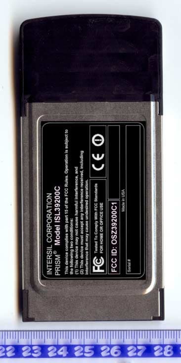
OSZ39200C1
Dec 08, 20032.4/5 GHz IEEE 802.11g/a WLAN Cardbus card
Equipment Class
NII - Unlicensed National Information Infrastructure TX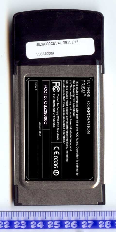
OSZ39000C
Oct 19, 20032.4/5 GHz IEEE 802.11g/a WLAN Cardbus card
Equipment Class
DTS - Digital Transmission System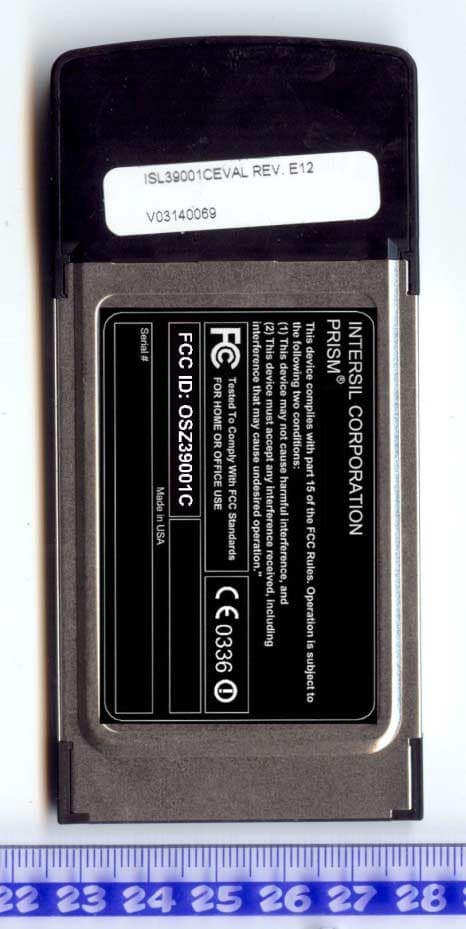
OSZ39001C
Oct 19, 20032.4/5 GHz IEEE 802.11g/a WLAN Cardbus card
Equipment Class
DTS - Digital Transmission System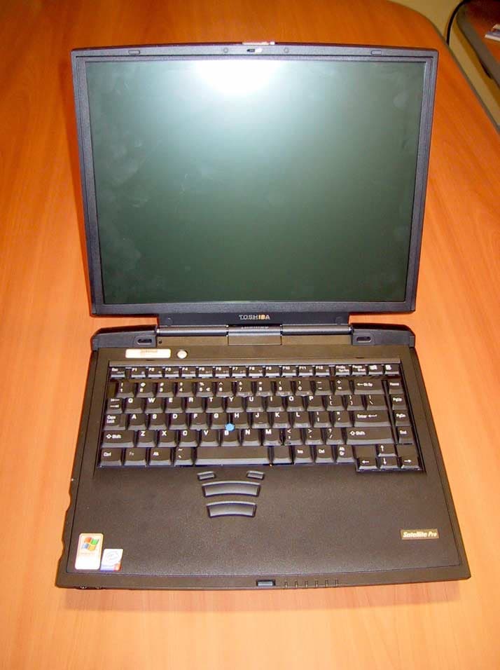
OSZ39000M1
Aug 20, 20032.4 GHz/5 GHz IEEE 802.11a/g WLAN MiniPCI card
Equipment Class
NII - Unlicensed National Information Infrastructure TX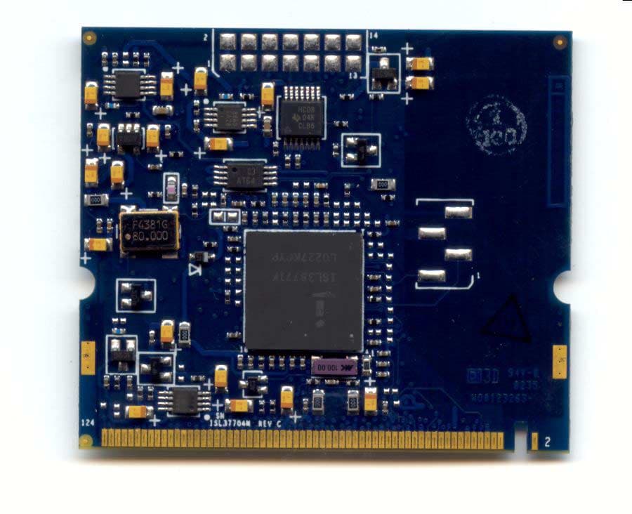
OSZ37704M
May 26, 20035 GHz IEEE 802.11a WLAN MiniPCI card
Equipment Class
NII - Unlicensed National Information Infrastructure TX