OTVGMRS1100GMRS/FRS Transceiver
SB Telcom Co Ltd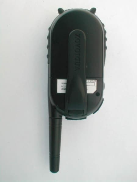
Click to zoom
Application Details
- Equipment Class
- FRF - Part 95 Family Radio Face Held Transmitter
- Date of Grant
- May 09, 2002
- Application Purpose
- Original Equipment
- Date of Application
- Jan 30, 2002
- Equipment Note
- GMRS/FRS Transceiver
- Frequency Range
- 462.55000000 - 462.72500000
- Company
- SB Telcom Co Ltd
- Country
- South Korea
Documents & Files
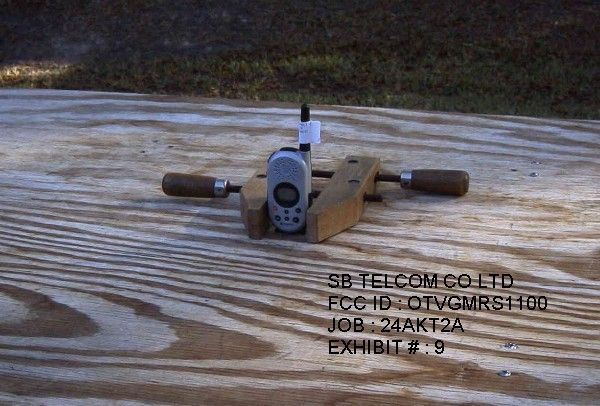
Document Text
Text extracted from the exhibit documents filed with the FCC. Open a document above to read the original.
Users Manual
128-6297 1 of 24 General Mobile Radio Service (GMRS)General Mobile Radio Service (GMRS) General Mobile Radio Service (GMRS)General Mobile Radio Service (GMRS) General Mobile Radio Service (GMRS) ModelModel ModelModel Model :: :: : GMRS1100-2CH GMRS1100-2CH GMRS1100-2CH GMRS1100-2CH GMRS1100-2CH Released:3-12-02. OwnerOwner OwnerOwner Owner ’s Man’s Man ’s Man’s Man ’s Man ualual ualual ual F F G © 2002 Audiovox Electronics Corp., Hauppauge, NY 11788 Customer Service 1-800-290-6650 128-6297 2 of 24 NEVER ATTEMPT TO CHARGE ALKALINE OR DRY CELL BATTERIES, AS BATTERIES MAY BURST CAUSING PERSONAL INJURY AND DAMAGE TO THE PRODUCT. WHEN RECHARGING NICKEL METAL HYDRIDE (Ni- MH) BATTERIES WITH THE SUPPLIED AUDIOVOX CHARGER AND WALL ADAPTER, USE ONLY AUDIOVOX-APPROVED RECHARGEABLE BATTER- IES. USE OF THE AUDIOVOX CHARGER WITH OTHER BRANDS OF BAT- TERIES IS NOT RECOMMENDED, AS BATTERY CHARGING TIMES WILL VARY WITH DIFFERENT BRANDS. REFER TO THE MANUFACTURER’S INSTRUCTIONS FOR CHARGING OTHER BRANDS OF BATTERIES. AVOID PLACING THE GMRS1100-2CH RADIO TRANSCEIVER FOR PRO- LONGED PERIODS OF TIME IN DIRECT SUNLIGHT OR TEMPERATURES BELOW -4° F (-20° C) OR ABOVE 140 ° F (60° C). KEEP THE ANTENNA AT 1 INCH (2.5 cm) AWAY FROM YOUR HEAD AND BODY. DO NOT USE YOUR GMRS1100-2CH RADIO TRANSCEIVER WITH A DAMAGED ANTENNA. PLACE THE RUBBER COVERS ON JACKS WHEN NOT IN USE. GMRS LICENSE: USE OF THIS RADIO WITHIN THE UNITED STATES REQUIRES AN FCC GMRS LICENSE. AN INDIVIDUAL 18 YEARS OF AGE OR OLDER, WHO IS NOT A REPRESENTATAIVE OF A FOREIGN GOVERNMENT, IS ELIGIBLE TO APPLY FOR A GMRS SYSTEM LICENSE. YOU WILL NEED TWO FORMS FROM THE FCC; FCC FORM 159 AND FCC FORM 605 MAIN FORM AND SCHEDULE F. YOU CAN FIND THE FORMS ONLINE AT: HTTP:// WWW.FCC.GOV/FORMPAGE.HTML, OR CALL 1-800-418-3676. CAUTION 2 128-6297 3 of 24 3 1.Battery Cover 2.Monitor/Function Confirmation Button 3.Detachable Carry Clip 4.Push-To-Talk (PTT) and Func- tion Confirmation Button 5.Antenna 6.External Speaker(SP.)/Micro- phone (MIC) Jacks 7.Built-in Speaker 8.Liquid Crystal Display (LCD) 9.Built-in Microphone Model GMRS1100-2CH (FCC License Required) 10.Up Channel/Volume Button 11.Down Channel/Volume Button 12.Function (F) Button 13.VOX Select Button 14.CALL/Function Confirmation Button 15.Power (PWR) On/Off Button 16.Combination Transmit Indi- cator (Red)/Receive and Monitor Indicator (Green) 17Battery Charging Contacts 3 5 4 1 2 9 13 11 8 10 12 7 15 14 16 6 M SP. MIC F F G 17 128-6297 4 of 24 4 Model GMRS 1100-2CH DISPLAY 1. Beep Tone Indicator: Icon appears when beep button confirmation tone is selected; icon disappears when tone is off. 2. Voice Activated Transmission (VOX) Indicator: This function allows hands free conversation. The icon appears when the VOX mode is active. 3. Scan Indicator: This function allows the user to scan a channel and/ or a tone code every .5 second to search for a valid signal. 4. Small Segment Display: Indicates the CTCSS tone code (1-38) function is active for the main channel in use. 5. Large Segment Display: Indicates the channel number in use between 1 and 22. 6. Transmit Indicator: The icon appears when the PTT button is pressed to initiate a transmission. 7. Transmit Call Indicator: Icon appears when the CALL button is pressed to alert the receiving party that a transmission is about to occur. 8. Battery Level Indicator: Icon indicates the battery charge level. 9. Power Saver Indicator: This icon appears when the unit is in the power saver mode due to idle time caused by transmit/receive inactivity. 10. F/G Indicators: When an FRS only channel is being used, the F icon appears; when an FRS/GMRS, or GMRS only, channel is being used, the G icon appears. 10 11 12 8 9 7 6 4 5 3 2 1 13 14 F G 128-6297 5 of 24 5 11. Volume Level Graph: The number of bars (1-8) indicates the volume level (8 indicates loudest) selected during transmit/receive operation. 12. Busy Indicator: This icon appears when there is activity on the channel selected for use. 13. Key Lock Indicator: Icon appears when the keypad is locked. This function disables keys such as channel up/down and MODE. 14. Dual Watch Mode Indicator: Icon appears when dual watch mode is active. Equipment and Accessories Supplied 1.Radio (2)GMRS1100-2CH 2.Owner’s Manual (1)128-6297 3.Batteries (8)Rechargeable NiMH 4.Dual Desk-Top ChargerDTC1100-2CH 5.AC Wall AdapterSBAC02 Powering the transceiver: Your GMRS1100-2CH radio transceiver operates on four AAA batteries. Alkaline batteries will provide slightly better performance than rechargeable batteries. Only the supplied Audiovox-approved rechargeable batteries can be recharged in the radio transceiver using the suppiled desk-top charger and associated wall adapter. This will ensure optimum performance for the GMRS1100-2CH. Battery charging time is typically 10-12 hours. Use of the Audiovox charger with other brands of batteries is not recommended as battery charging times will vary. Refer to the manufacturer’s instructions for charging other brands of batteries. Batteries There are three methods of powering the GMRS1100-2CH: 1. Alkaline Batteries. WARNING: Do not attempt to recharge Alkaline batteries. 2. Audiovox Rechargeable Ni-MH Batteries - (Rechargeable Ni-MH batteries, Wall Adapter and Charging Stand included). 128-6297 6 of 24 6 2. Slide the cover down and then lift cover at bottom to open.Remove cover. 3. Insert four AAA batteries (positive (+) end toward the top begining at left side and alternating positive terminals as shown). 1. Using thumb, press down on battery cover at arrow and slide cover down to open. Use only Audiovox-approved rechargeable batteries and charger when charging batteries internal to the unit. NOTE: To extend battery life, avoid overcharging the batteries. 3. Various Brands of Rechargeable Batteries - Use of the Audiovox charger with other brands of rechargeable batteries is not recommended, as battery charging times will vary with different brands of batteries. Refer to the manufacturer’s…
Text truncated - open the document above for the full version.
Cover Letter(s)
849 NW State Road 45 • P. O. Box 370 • Newberr y, Florida 32669 USA Telephone (352) 472-5500 • (888) 472-2424 • FAX (352) 472-2030 • email: [email protected] February 28, 2002 Federal Communications Commission Authorization and Evaluation Division 7435 Oakland Mills Road Columbia, MD 21045 SUBJECT: SB TELCOM CO., LTD.’S APPLICATION FOR CERTIFICATION FOR THEIR FCC ID: OTVGMRS1100 CONFIRMATION #: EA479274 To Whom It May Concern: The above mentioned application, testing report, and all exhibits were submitted on 1/31/02. Once the applicant received his file copy of the report, he questioned us on the output power. They then advised us of a switch that we should have used to change the device to HIGH output power. We rechecked their high output power and found that it is .8 Watts instead of the reported .23 Watts reported. I’ve uploaded a modified test report reflecting the correct output power of .8 Watts and this letter will serve as a request to correct the 731 form. No modifications were made to the device; the output power measurement was taken on the original sample sent to us for testing purposes. Should you have any questions with regards to this, please advise. Regards, Sharon A. Hoffman
Cover Letter(s)
TIMCO ENGINEERING, INC. 849 N.W. STATE ROAD 45 NEWBERRY, FL 32669 PHONE: 888-472-2424 OR 352-472-5500 FAX: 352-472-2030 EMAIL: [email protected] April 3, 2002 Mr. Joe Dichoso Federal Communications Commission Authorization and Evaluation Division 7435 Oakland Mills Road Columbia, MD 21046 Ref: SB TELCOM CO., LTD.’S FCC ID: OTVGMRS1100 Confirmation #: EA479274, Correspondence ID #: 22462 Dear Joe: Per your request of 3/28/02; 1. Page 2 of the tuning procedure has been revised and uploaded to the file. 2. The transceiver has a power setting potentiometer (RV301) for setting the FRS output power levels on the FRS channels. The microprocessor activates a transistor that limits the output power on FRS channels. The LCD display of the transceiver displays a G or F on the appropriate channel to let the customer know that they are on an FRS or GMRS channel. 3. The output power reported is radiated using the substitution method. The test report has been modified to show this and has been uploaded to the file. 4. The device was tuned up to the proper values in the tuning procedure when the device was tested. 5. The user’s manual has been modified to show that a license is required for the GMRS channels. A notice will also be placed inside the box. I’ve uploaded the revised user’s manual for your reference. Should you have any questions or require any further information, please advise. Regards, Mario R. de Aranzeta Engineer
Cover Letter(s)
849 NW State Road 45 • P. O. Box 370 • Newberr y, Florida 32669 USA Telephone (352) 472-5500 • (888) 472-2424 • FAX (352) 472-2030 • email: [email protected] April 16, 2002 Mr. Joe Dichoso Federal Communications Commission Authorization and Evaluation Division 7435 Oakland Mills Road Columbia, MD 21045 SUBJECT: SB TELCOM CO., LTD.’S APPLICATION FOR CERTIFICATION FOR THEIR FCC ID: OTVGMRS1100 CONFIRMATION #: EA479274 CORRESPONDENCE REFERENCE #: 22571 Dear Joe: Per your request of 4/9/01 – 1. I’ve uploaded the contents of the informational insert that the applicant will include inside the box. 2. The manufacturer has questioned the request for a SAR report since the highest output power measured was 0.8 Watts. We thought that PTT radios with an output power of 1.5 Watts and above were required to be tested for SAR. They have modified their tuning procedure to match the measured output power. Should you have any questions or require any further information with regards to this, please advise. Regards, Sharon A. Hoffman
Cover Letter(s)
Timco Engineering Inc. 849 NW State Road 45 Newberry FL 32669 Page 1 of 2 From: Mario de Aranzeta [email protected] To: Joe Dichoso [email protected] FCC Application Processing Branch Re: FCC ID OTVGMRS1100 Applicant: SB Telecom Co. Ltd. Correspondence Reference Number: 22708, 22710 731 Confirmation Number: EA479274 1) The previous tune up procedure indicated 2W conducted for GMRS frequencies and 0.5 W for FRS frequencies. This produced an ERP of .8 W for GMRS and .23 W for FRS. The last tune up procedure now indicates only .78 W conducted for GMRS and NO procedure for the FRS. Please submit a corrected tune up procedure for both GMRS and FRS. 2) Since you lowered the tune up procedure from 2 W to .78 W on the GMRS channel, new radiated and ERP measurements are required. Based on radiated ERP measurement of .8 W when the device was tuned at 2 W conducted output, the ERP for the GMRS should be about .312 W. Please confirm with measurements after the device output on the GMRS frequency is tuned to the .78 W. Joe, I’ve talked to the customer and after a lot of interpreting have come to the understanding from them that they misunderstood the previo us email questio ns. I’ve taken o n the respo nsibility of answering the questions o n the tune up procedure here. On 3/28/02 in correspondence 22462. 1) The tune up procedure indicates only 2 W conducted output power. The circuit description indicates 2 Watts conducted output power for GMRS and .5W FRS. How is the output power properly tuned (or fixed) on the FRS channels? (The output power in the FRS channels must not be tuned to GMRS output power levels). Yes the tune up procedure and user’s manual did indicate that a conducted power of 2 Watts may be possible on a GMRS channel. The tune up procedure enclosed as page 2 now includes a procedure for both GMRS and FRS channels. In this procedure, we have limited the output po wer to 1.9 Watts conducted. This sho uld not change the radiated as reported in the test report by any significant amo unt. We are also uploading a revised user’s manual that co ntains the correct o utput power information. Based on these measurements, this indicates that the gain of the antenna is negative which is supported by the ERP power of 0.78 Watts for the GMRS and 0.23 Watts for the FRS. Regards, Mario de Aranzeta Engineer Timco Engineering Inc. 849 NW State Road 45 Newberry FL 32669 Page 2 of 2 b. Connect DC 6.0, Voltage preset to EUT. c. Connect “po wer meter” and “dummy load” (50 o hm). d. Adjust Tx frequency by adjusting trimmer CT201. e. Connect AF oscillator to mic terminals. f. Adjust the frequency of the AF oscillator to 1 kHz and adjust AF level for 70 mV. g. Check using an oscilloscope and modulation meter for a max. frequency deviation of +-2.5 kHz. c) Transmitter Test a. Output Power Test The RF power o utput with 6.0 V dc applied sho uld be Max. 1.9 Watts o n a GMRS frequency. Reject any unit that exceeds 1.9 Watts o utput. The RF power o utput with 6.0 V dc applied sho uld be Max. 0.5 Watts o n a FRS frequency. This can be set using RV301. b. Audio Response Connect AF oscillator to Mic terminals and co nfirm that the audio level isn’t distorted using an oscilloscope (300 Hz to 3 kHz). Use a 1 kHz to ne as the basis. c. Degree of Modulation Test. 1. Co nnect AF oscillator to the mic terminals and then adjust the level to 140 mV. 2. Using an oscilloscope monitor the waveform and using a modulation meter ensure that the deviation doesn’t exceed +- 2.5 kHz while sweeping the audio frequency from 300 Hz to 3 kHz. The PTT switch sho uld be depressed during this test. d. Spectrum Test 1. Pad the RF o utput of the radio with attenuators sufficient to keep from overloading or harming a spectrum analyzer input. 2. Co nnect a spectrum analyzer and push the PTT butto n. 3. Observe the spectrum from 400 MHz to 5000 MHz. The harmo nics sho uld be 60 dBc below the carrier. d) Receiver a. Preparation 1. Adjust the power supply for 6.0 Vdc. 2. Adjust the audio voltage level to 0.8Vrms into an 8 o hm load after power on. b. Co nnectio n method
Cover Letter(s)
TIMCO ENGINEERING, INC. 849 N.W. STATE ROAD 45 P.O. BOX 370 NEWBERRY, FL 32669 PHONE: 888-472-2424 OR 352-472-5500 FAX: 352-472-2030 EMAIL: [email protected] May 7, 2022 Mr. Joe Dichoso Federal Communications Commission Authorization and Evaluation Division 7435 Oakland Mills Road Columbia, MD 21046 Ref: SB TELCOM CO., LTD.’S FCC ID: OTVGMRS1100 Confirmation #: EA479274, Correspondence ID 22785 Dear Joe: The application still wishes to obtain their approval without having to go through the extra expense of SAR testing. They have asked us to reduce the conducted output power and we have done so. I’ve uploaded another revised test report which reflects these changes along with a revised user’s manual and tuning procedure showing the lower output power. The changes made to the device are as follows: Changed R308 from 2.2k ohm to 1.5k ohm. Should you have any questions or require any further information, please advise. Regards, Mario R. de Aranzeta MRA/sh
ID Label/Location Info
34.00 mm 1 2 . 0 0 m m
Parts List/Tune Up Info
b. Connect DC 6.0, Voltage preset to EUT. c. Connect “po wer meter” and “dummy load” (50 o hm). d. Adjust Tx frequency by adjusting trimmer CT201. e. Connect AF oscillator to mic terminals. f. Adjust the frequency of the AF oscillator to 1 kHz and adjust AF level for 70 mV. g. Check using an oscilloscope and modulation meter for a max. frequency deviation of +-2.5 kHz. c) Transmitter Test a. Output Power Test The RF power o utput with 6.0 V dc applied sho uld be Max. 1.4 Watts o n a GMRS frequency. Reject any unit that exceeds 1.4 Watts o utput. The RF power o utput with 6.0 V dc applied sho uld be Max. 0.5 Watts o n a FRS frequency. This can be set using RV301. b. Audio Response Connect AF oscillator to Mic terminals and co nfirm that the audio level isn’t distorted using an oscilloscope (300 Hz to 3 kHz). Use a 1 kHz to ne as the basis. c. Degree of Modulation Test. 1. Co nnect AF oscillator to the mic terminals and then adjust the level to 140 mV. 2. Using an oscilloscope monitor the waveform and using a modulation meter ensure that the deviation doesn’t exceed +- 2.5 kHz while sweeping the audio frequency from 300 Hz to 3 kHz. The PTT switch sho uld be depressed during this test. d. Spectrum Test 1. Pad the RF o utput of the radio with attenuators sufficient to keep from overloading or harming a spectrum analyzer input. 2. Co nnect a spectrum analyzer and push the PTT butto n. 3. Observe the spectrum from 400 MHz to 5000 MHz. The harmo nics sho uld be 60 dBc below the carrier. d) Receiver a. Preparation 1. Adjust the power supply for 6.0 Vdc. 2. Adjust the audio voltage level to 0.8Vrms into an 8 o hm load after power on. b. Co nnectio n method
Test Report
APPLICANT: SB TELCOM CO., LTD. FCC ID: OTVGMRS1100 REPORT #: T:\S\SBTELE\24akt2a\Corres-22785\MODIFmodifiedTESTREPORT.doc TABLE OF CONTENTS TABLE OF CONTENTS LIST APPLICANT: SB TELCOM CO., LTD. FCC ID: OTVGMRS1100 TEST REPORT: PAGE 1......COVER SHEET - GENERAL INFORMATION & TECHNICAL DESCR. PAGE 2......TECHNICAL DESCRIPTION CONTINUED PAGE 3......RF POWER OUTPUT PAGE 4......MODULATION CHARACTERISTICS PAGE 5......AUDIO FREQUENCY RESPONSE GRAPH PAGE 6......MODULATION LIMITING GRAPH – 300Hz PAGE 7......MODULATON LIMITING GRAPH – 1000Hz PAGE 8......MODULATION LIMITING GRAPH – 3000Hz PAGE 9......AUDIO LOW PASS FILTER GRAPH PAGE 10.....OCCUPIED BANDWIDTH PAGE 11.....OCCUPIED BANDWIDTH PLOT PAGE 12.....OCCUPIED BANDWIDTH PLOT - CW PAGE 13.....SPURIOUS EMISSIONS AT ANTENNA TERMINALS PAGE 14.....UNWANTED RADIATION PAGE 15.....METHOD OF MEASURING RADIATED SPURIOUS EMISSIONS PAGE 16.....FREQUENCY STABILITY PAGE 17.....LIST OF TEST EQUIPMENT EXHIBITS CONTAINING: EXHIBIT 1.........FCC ID LABEL SAMPLE & SKETCH OF LOCATION EXHIBIT 2A........EXTERNAL PHOTO – FRONT VIEW EXHIBIT 2B........EXTERNAL PHOTO – REAR VIEW – WITH CLIP EXHIBIT 2C........EXTERNAL PHOTO – REAR VIEW – W/OUT CLIP EXHIBIT 2D........EXTERNAL PHOTO – SIDE VIEW EXHIBIT 2E........EXTERNAL PHOTO – TOP VIEW EXHIBIT 3A........INTERNAL PHOTO – COMPONENT VIEW EXHIBIT 3B........INTERNAL PHOTO – COPPER VIEW EXHIBIT 4.........BLOCK DIAGRAM EXHIBIT 5.........SCHEMATICS EXHIBIT 6.........USER'S MANUAL EXHIBIT 7.........CIRCUIT DESCRIPTION EXHIBIT 8.........TUNING PROCEDURE EXHIBIT 9.........TEST SET UP PHOTO APPLICANT: SB TELCOM CO., LTD. FCC ID: OTVGMRS1100 REPORT #: T:\S\SBTELE\24akt2a\Corres-22785\MODIFmodifiedTESTREPORT.doc Page 1 of 17 GENERAL INFORMATION REQUIRED FOR CERTIFICATION 2.1033(c)(1)(2) SB TELCOM CO., LTD. will manufacture the FCCID: OTVGMRS1100 GMRS CHANNELS TRANSCEIVER in quantity, for use under FCC RULES PART 95. SB TELCOM CO., LTD. #25-49, JUAN5-DONG, NAM-KU INCHEON KOREA 2.1033 (c) TECHNICAL DESCRIPTION 2.1033(c)(3) Instruction book. A draft copy of the instruction manual is included as EXHIBIT 6. 2.1033(c) (4) Type of Emission: 10K5F3E 95.631 Bn = 2M + 2DK M = 3000 D = 1.75K K = 1 Bn = 2(3000)+2(2250) = 10.5 k GMRS Authorized Bandwidth 20.0 kHz 2.1033(c)(5) GMRS Frequency Range: 462.5500 - 462.7250 MHz 95.621 2.10311c)(6)(7) The Maximum Output Power Rating: GMRS - .62 Watts FRS - .23 Watts FRS Authorized Bandwidth 12.5 kHz 2.1033(c)(5) FRS Frequency Range: 1. 462.5625 8. 467.5625 95.627 2. 462.5875 9. 467.5875 3. 462.6125 10. 467.6125 4. 462.6375 11. 467.6375 5. 462.6625 12. 467.6625 6. 462.6875 13. 467.6875 7. 462.7125 14. 467.7125 MHz 2.1033(c)(6)(7) Power Output shall not exceed 0.50 Watts effective 95.639 radiated power. There can be no provisions for 95.649 increasing the power or varying the power. APPLICANT: SB TELCOM CO., LTD. FCC ID: OTVGMRS1100 REPORT #: T:\S\SBTELE\24akt2a\Corres-22785\MODIFmodifiedTESTREPORT.doc Page 2 of 17 2.1033(c)(8) DC Voltages and Current into Final Amplifier: FINAL AMPLIFIER ONLY FOR LOW POWER SETTING INPUT POWER: (6.0V)(.210A) = 1.26 Watts FOR HIGH POWER SETTING INPUT POWER:(6.0V)(.550A) = 3.30 Watts 2.1033(c)(9) Tune-up procedure. The tune-up procedure is included as EXHIBIT # 8. 2.1033(c)(10) Complete Circuit Diagrams: The circuit diagram is included as EXHIBIT 5 of this report. The block diagrams are included as EXHIBIT 4 of this report. 2.1033(c)(11) A photograph or a drawing of the equipment identification label is included as exhibit No. 1. 2.1033(c)(12) Photographs(8"X10") of the equipment of sufficient clarity to reveal equipment construction and layout, including meters, labels for controls, including any view under shields. See exhibits 2-3. 2.1033(c)(13) Digital modulation is not allowed. 2.1033(c)(14) The data required by 2.1046 through 2.1057 is submitted below. APPLICANT: SB TELCOM CO., LTD. FCC ID: OTVGMRS1100 REPORT #: T:\S\SBTELE\24akt2a\Corres-22785\MODIFmodifiedTESTREPORT.doc Page 3 of 17 95.639 Power Output shall not exceed 50.0 Watts effective radiated power. There can be no provisions for 95.649 increasing the power or varying the power. RF power output. 2.1046(a) RF power is measured by radiated field strength using the substitution method. With a nominal battery voltage of 6.0 V, and the transmitter properly adjusted the RF output measures: OUTPUT POWER: GMRS: .62 Watts ERP FRS: .23 Watts ERP 2.1046(a) RF power output. The test procedure used was TIA/EIA-603 S2.2.1. APPLICANT: SB TELCOM CO., LTD. FCC ID: OTVGMRS1100 REPORT #: T:\S\SBTELE\24akt2a\Corres-22785\MODIFmodifiedTESTREPORT.doc Page 4 of 17 2.1047(a)(b) Modulation characteristics: AUDIO FREQUENCY RESPONSE The audio frequency response was measured in ac- cordance with TIA/EIA Specification 603. The audio frequency response curve is shown on the next page. The audio signal was fed into a dummy microphone circuit and into the microphone connector. The input required to produce 30 percent modulation level was measured. See Page 5 of report. 2.1047(b) Audio input versus modulation The audio input level needed for a particular per- percentage of modulation was measured in accor- dance with TIA/EIA Specification 603. The audio input curves versus modulation are on the following pages. Curves are provided for audio input frequen- cies of 300, 1000, and 3000 Hz. See Pages 6,7 & 8 of report. 95.637 Post Limiter Filter Each GMRS transmitter, except a mobile station transmitter with a power of 2.5 Watts or less, must be equipped with an audio low pass filter. At any frequency between 3 & 20 kHz the filter must have an attenuation of 60log (f/3) greater than the attenuation at 1 kHz. See Page 9 of report. APPLICANT: SB TELCOM CO., LTD. FCC ID: OTVGMRS1100 REPORT #: T:\S\SBTELE\24akt2a\Corres-22785\MODIFmodifiedTESTREPORT.doc Page 5 of 17 SB Telcom Co. LTD. GMRS1100 -60 -55 -50 -45 -40 -35 -30 -25 -20 100100010000 Frequency dBmV audio response APPLICANT: SB TELCOM CO., LTD. FCC ID: OTVGMRS1100 REPORT #: T:\S\SBTELE\24akt2a\C…
Text truncated - open the document above for the full version.
Contact Information
Applicant
H. Y. Cho(R & D Manager)
Technical Contact
Timco Engineering, Inc.Mario R de Aranzeta
[email protected]888-472-2424
849 · Newberry, Florida · United States
Non-Technical Contact
Timco Engineering, Inc.Sharon A Hoffman
[email protected]888-472-2424
Test Firm
Timco Engineering, Inc.S Sanders
Technical Specifications
| # | Rule Parts | Frequency Range | Power Output | Emission | Tolerance |
|---|---|---|---|---|---|
| 3 | 95A | 462.55 MHz - 462.725 MHz | 620.00 mW | 10K5F3E | 5 ppm |
Other Applications from SB Telcom Co Ltd
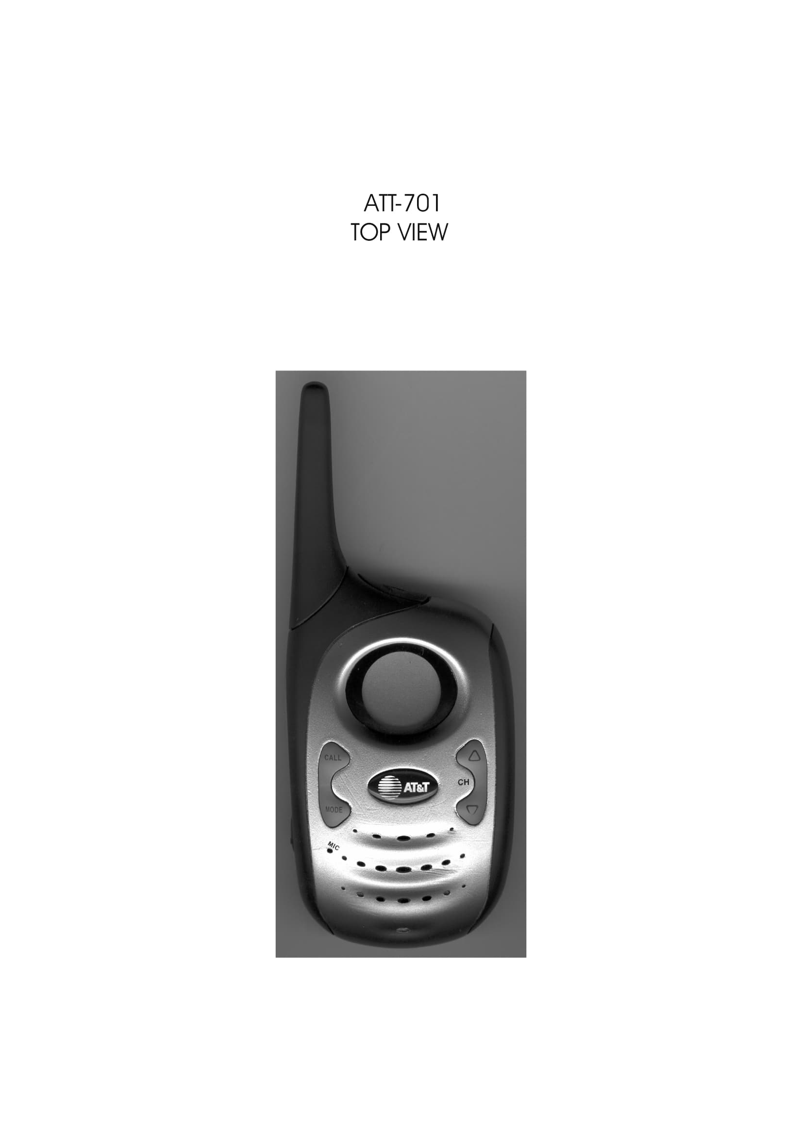
OTVATT701
Jun 02, 2002Family Radio Transceiver
Equipment Class
FRF - Part 95 Family Radio Face Held Transmitter
OTVSBTFR531-2
Feb 21, 2002family radio tranceiver
Equipment Class
FRF - Part 95 Family Radio Face Held Transmitter
OTVSBTFR541-2
Jan 31, 2002Family Radio Transceiver
Equipment Class
FRF - Part 95 Family Radio Face Held Transmitter
OTVSBTFR580-2CH
Oct 29, 2001family radio transceiver
Equipment Class
FRF - Part 95 Family Radio Face Held Transmitter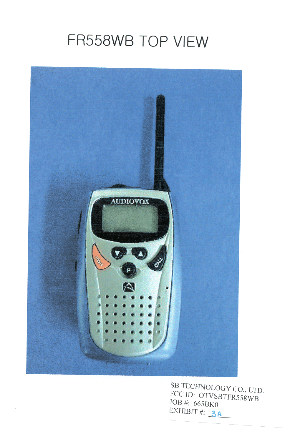
OTVSBTFR558WB
Jul 26, 2001FRF - Part 95 Family Radio Face Held Transmitter
Equipment Class
FRF - Part 95 Family Radio Face Held Transmitter