OU4-GSGuardsman Transmitter GS010
Xanboo, Inc.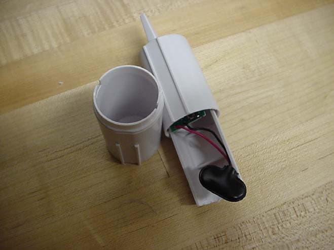
Click to zoom
Application Details
- Equipment Class
- DSC - Part 15 Security/Remote Control Transmitter
- Date of Grant
- Feb 17, 2004
- Application Purpose
- Original Equipment
- Date of Application
- Feb 17, 2004
- Equipment Note
- Guardsman Transmitter GS010
- Frequency Range
- 418.00000000 - 418.00000000
- Company
- Xanboo, Inc.
- Country
- United States
Documents & Files
Document Text
Text extracted from the exhibit documents filed with the FCC. Open a document above to read the original.
Users Manual
Exhibit J: Users Manual Xanboo Guardsman Transmitter GS010 RAPID DEPLOYMENT INTRUDER DETECTION SYSTEM GUARDSMAN ADD-ON MOTION DETECTOR GS010 USER’S GUIDE DRILLING TEMPLATE FOR WALL MOUNTING MOTION DETECTOR /// For wall-mounting Motion Detector(s), drill two holes using a 1/4" drill bit and the template below. Insert supplied wall anchors into holes and secure camera to wall with supplied screws. DRILL HOLE IN THIS POSITION DRILL HOLE IN THIS POSITION ADDING A NEW MOTION SENSOR TO A ZONE /// 1. Press the ‘SENSOR DISCOVERY’ button found on the rear panel of the Receiver Base. The Power Light on the front panel of the Receiver Base will begin flashing. This indicates the unit is waiting for a sensor to register itself. 2. Connect a battery to ONE motion sensor, and as you do so the small LED on the sensor will flash. When this occurs the Power Light on the Receiver Base will stop flashing, and all of the LED’s for the 3 zones will light up. (Note: only power one Motion Sensor at a time) 3. Choose which zone you would like to register the sensor to and then simply push the button under that LED. The sensor is now registered to that zone. Once a Motion Sensor is registered with a particular zone, even if the sensor loses power for a prolonged period of time, the Receiver Base will still recognize the sensor when power is restored. NOTE: It is important to power only one Motion Sensor at a time since as soon as you power it up the Receiver Base, if in discovery mode, will recognize the sensor. To facilitate set up, you should power up one sensor, assign it to a group, and then repeat the process for the other sensors. CLEARING A ZONE’S MEMORY /// Press and hold the ‘SENSOR DISCOVERY’ button on the rear panel, after 2 seconds the unit will beep, then release the button. All zone LED’s will now light up. Press the button for the zone that you would like to clear. To clear all zones, repeat the above for each zone. MOTION SENSOR MOUNTING /// The Guardsman Motion Detector are constructed with UV resistant ABS plastic allowing for indoor or outdoor use. NOTE: For optimum range, the Motion Sensors should not be used on metal doors, metal door frames or metal objects. 1. Peel the paper strip from the double-sided tape located on the back of the sensor Wall Mounting Bracket. You can also mount the sensor more securely using the screws in the hardware kit. Using the drilling template on the back of the instruction guide, drill two small holes for the screws, ideally 6 - 8 feet off the ground. 2. Screw the Wall Bracket into place. PRODUCT DESCRIPTION /// The Xanboo ™ Guardsman GS010 Motion Detector is a simple plug n’ play unit that allows for convenient monitoring of multiple zones by wireless motion sensors. The system is ideal for monitoring residential homes, small businesses and even for situations that require a “rapid and mobile deployment” system such as a boat, RV or campsite at night. PACKAGE CONTENTS /// n (1) Motion Sensors with Wall and Table Top Mounts n (1) Hardware Kit n (1) Installation Guide n (1) 9V Alkaline Battery ALARM UNIT /// Every Guardsman System has 3 zones that can be armed independently from each other. In addition, you can have up to 3 Motion Sensors per zone, for a total of 9 Motion Sensors. If motion is detected in a particular zone, such as the backyard zone, downstairs zone, or pool area zone, the Receiver Base will sound an alarm and the LED on the Receiver Base for that particular zone will blink red. The advantage to having up to 3 Motion Sensors in one zone such as the backyard or pool area, is that you can cover a much larger area using several sensors than you could with just one. Each zone can independently be turned ‘OFF’, set to ‘ALERT MODE’ in which it will only give short “beeps”, or set to sound a full and continuous alarm in the ‘ALARM MODE’. When set in ‘ALARM MODE’, the LED for the zone that detects motion will flash red. This alarm then continues for 30 seconds unless the alarm reset button is pressed. You can alternate between settings by pressing the button under each zone LED. n NO LIGHT: Zone is off n LED IS GREEN: Alert mode n YELLOW: Alarm mode 2 ALARM RESET ZONE 3 BUTTON ZONE 2 BUTTON ZONE 1 BUTTON ZONE LEDS POWER LIGHT FRONT PANEL REAR PANEL I WIRELESS RECEIVER AUDIO ALERT ZONE 1 POOL AREA SENSORS ZONE 2 INDOOR SENSORS ZONE 3 OUTDOOR SENSORS POOL BATTERY GOES HERE 12VDC ANTENNA VOLUME SENSOR DISCOVER POWER ON/OFF WALL/TABLE TOP MOUNTSMOTION DETECTORHARDWARE KIT 34 HOW LONG WILL THE MOTION SENSOR BATTERY LAST? The battery is expected to last up to 12 months. This will depend on actual use and how often the sensor is triggered. HOW MANY SENSORS CAN I REGISTER WITH THE RECEIVER BASE? The Receiver Base can support up to 9 Sensors (3 per zone). TECHNICAL SPECS /// n Manchester encoded OOK modulation with rolling code for security PIR: Long range (20 feet at 20ºC) motion sensor with false trigger reduction LED: Flashes to indicate motion event Battery: 9V Alkaline (provided). Plus low battery alert Transmitter: 418MHz @ FCC approved power limit Range: 200 feet outdoors, 40 feet indoors Temperature range: 14ºF - 104ºF (-10ºC - 40ºC) Case: High impact ABS Size: 5.35” (136mm) high, 1.40” (36mm) diameter. Plus stand APPROVALS /// This device complies with part 15 of the FCC rules. Operation is subject to the following two conditions: (1) this device may not cause harmful interference, and (2) this device must accept any interference received, including interference that may cause undesired operation. CE directive 93/68/EEC, EMC directive 89/336/EEC, LV directive 73/23/EEC. This class B digital apparatus complies with Canadian ICES-003. The user is cautioned that changes and modifications made to the equipment without the approval of manufacturer could void the user's authority to operate this equipment. WARRANTY /// This product has a one year manufacturer’s warranty which covers parts and labor only. In the unlikely event that you encounter a technical or…
Text truncated - open the document above for the full version.
Block Diagram
Exhibit F: Block Diagram Xanboo Guardsman Transmitter GS010
Cover Letter(s)
Exhibit K: Letter of Confidentiality Xanboo Guardsman Transmitter GS010 American Telecommunications Certification Body, Inc. 6731 Whittier Ave. McLean, VA 22101 February 6, 2004 RE: Certification Application FRN: 0007774151 FCC ID: OU4-GS Please be advised the following information is to be held confidential on behalf of Company. • Schematics • Theory of operation Thank you, M Ghalebi Senior Vice president (Engineering)
Cover Letter(s)
Exhibit I: Letter of Authorization Xanboo Guardsman Transmitter GS010
Cover Letter(s)
American Telecommunications Certification Body Inc. 6731 Whittier Ave, McLean, VA 22101 February 7, 2004 RE: FCC ID: QU4-GS Attention: Mike Royer I have a few comments on this Application. 1. Please note that recent interpretations from the FCC have reiterated that the operational description of a device is to include a brief explanation of how the device actually works and not simply an overview of the purpose of the device. Please provide an operational description of this device that explains how the device works. 2. Please provide the users manual with all of the appropriate FCC statements. 3. Please clearly indicate how the receive antenna, cable, preamplifier (if used) and any other factor was included in the analyzer readings. Please provide evidence of the formula used to include these factors. 4. Please note that the spurious emissions limits for frequencies over 470MHz but not in the restricted bands is 1250 uV/m (or 61.9dBuV/m). This means that using your specified distance factor of 9.5dB, your corrected limit should be 71.4dBuV/m.. Please explain why you use the limits found in your tables for 1 meter measurement distances. Please show all correction factors associated with measured results and how they are applied (i.e. distance factor, transducer factors, etc). 5. Please provide evidence that the device meets the automatic or manual turn off requirements of 15.231a2&3. This is generally done in the operational description. 6. Please provide the schematics for this device. Dennis Ward mailto:[email protected] The items indicated above must be submitted before processing can continue on the above referenced application. Failure to provide the requested information may result in application termination. Correspondence should be considered part of the permanent submission and may be viewed from the Internet after a Grant of Equipment Authorization is issued. Please do not respond to this correspondence using the email reply button. In order for your response to be processed expeditiously, you must submit your documents through the AmericanTCB.com website. Also, please note that partial responses increase processing time and should not be submitted. Any questions about the content of this correspondence should be directed to the sender.
External Photos
Appendix E2: External EUT Photos Xanboo Guardsman Transmitter GS010 Xanboo Guardsman Transmitter GS010 EUT Front View EUT Rear View Xanboo Guardian Transmitter GS010 EUT Disassembled EUT Bottom Open
ID Label/Location Info
Exhibit C: Label Location Xanboo Guardsman Transmitter GS010 Xanboo Guardsman Serial No This device complies with part 15 of the FCC rules. FCC ID Number: OU4-GS Xanboo Inc, New York USAMade in China Tested to Comply With FCC Standards FOR HOME OR OFFICE USE Operation is subject to the following two conditions: 1) This device may not cause harmful interference, and 2) This device must accept any interference received, including interference that may cause undesired operation. Standards: 93/68/EEC, 89/336/EEC, BS EN 50082-1:1992, 73/23/EEC, EN60950:1992 CE
Internal Photos
Appendix E1: Internal EUT Photos Xanboo Guardsman Transmitter GS010 Xanboo Guardsman Transmitter GS010 EUT PCB Front View PCB Rear View
Test Report
Professional Testing (EMI), Inc. Report No. 03372-10 Page 2 of 15 Exhibit B: Test Report Xanboo Guardian Transmitter GS010 Professional Testing (EMI), Inc. Report No. 03372-10 Page 3 of 15 Project Number: 03372-10 Prepared for: Xanboo 1626 Vineyard Grand Praire , TX 75052 By Professional Testing (EMI), Inc. 1601 FM 1460, Suite B Round Rock, Texas 78664 May 2003 CERTIFICATION Electromagnetic Interference Test Report Xanboo Guardsman Transmitter GS010 (Intentional Radiator ) Professional Testing (EMI), Inc. Report No. 03372-10 Page 4 of 15 Table of Contents Title Page .........................................................................................................................................1 Table of Contents .............................................................................................................................2 Certificate of Compliance ................................................................................................................3 1.0 EUT Description ......................................................................................................................4 1.1 EUT Operation.........................................................................................................................4 2.0 Electromagnetic Emissions Testing.........................................................................................4 2.1 Test Procedure .....................................................................................................................5 2.2 Test Criteria ........................................................................................................................5 2.3 Test Results ..........................................................................................................................6 3.0 Occupied Bandwidth Measurements .......................................................................................6 3.1 Test Procedure .....................................................................................................................6 3.2 Test Criteria .........................................................................................................................6 3.3 Test Results ..........................................................................................................................6 4.0 Antenna Requirement ..............................................................................................................7 4.1 Evaluation Procedure ...........................................................................................................7 4.2 Evaluation Criteria ...............................................................................................................7 4.3 Evaluation Results ...............................................................................................................7 5.0 Modifications to Equipment ....................................................................................................8 6.0 List of Test Equipment.............................................................................................................8 Figures Figure 1: Radiated Emissions Test Setup ........................................................................................9 Appendices Appendix A: Emissions Data Sheet................................................................................................ 10 Appendix B: Occupied Bandwidth Data Sheets............................................................................. 15 THIS REPORT SHALL NOT BE REPRODUCED EXCEPT IN FULL, WITHOUT THE WRITTEN APPROVAL OF PROFESSIONAL TESTING (EMI), INC. 1601 FM 1460, Suite B Round Rock, Texas 78664 512/244-3371 Fax 512/244-1846 Applicant: Xanboo Applicant’s Address: 1626 Vineyard Grand Praire, TX 75052 Model: None FCC ID: OU4-GS Project Number: 03372-10 Test Dates: March 20, 2003 I, Jeffrey A. Lenk, for Professional Testing (EMI), Inc., being familiar with the FCC rules and test procedures have reviewed the test setup, measured data and this report. I believe them to be true and accurate. The Xanboo, Guardsman Transmitter GS010 was tested to and found to be in compliance with FCC Part 15 Subpart C for an Intentional Radiator. The highest emissions generated by the above equipment are listed below: Frequency (MHz) Level (dBμV/m) Limit (dBμV/m) Margin (dB) GS010 Fundamental 418 79.6 80.3 -0.7 GS010 Harmonics 3762 59.9 69.8 -9.9 Occupied Bandwidth 166 (kHz) 1045 (MHz) ______________________________ Jeffrey A. Lenk President This report has been reviewed and accepted by Xanboo. The undersigned is responsible for ensuring that Xanboo, Guardsman Transmitter GS010 will continue to comply with the FCC rules. ______________________________ Certificate of Compliance Professional Testing (EMI), Inc. Page 4 of 15 1.0 EUT Description The Equipment under Test (EUT) is the Xanboo, Guardsman Transmitter GS010 . The Guardsman Transmitter GS010 is battery powered. The GS010 is activated when it senses infrared motion. The EUT operates at 418 MHz and are designed for compliance with 47 CFR 15.231 of the FCC rules. Specific test requirements for the devices include the following: 47 CFR 15.231 Fundamental Transmit Power 47 CFR 15.231 & 15.205 Spurious Radiated Power 47 CFR 15.35 Average Radiated Signal 47 CFR 15.231 Occupied Bandwidth 47 CFR 15.203 Antenna Requirement The system tested consisted of the following: Manufacturer & Model Serial # FCC ID # Description Xanboo, Guardsman Transmitter GS010 N/A OU4-GS Gate Sensor 1.1 EUT Operation The Xanboo Guardsman Transmitter GS010 was tested using internal batteries. The frequency of the transmitting signal is 418 MHz. The Transmitter operating at 418 MHz under normal configuration can only be triggered once per five seconds and transmits a recognition code for 52 milliseconds. For the purpose of testing, a special mode was used, for most of the testing, allowing the Door Sensor …
Text truncated - open the document above for the full version.
Test Setup Photos
Appendix D: Test Setup Photos Xanboo Guardsman Transmitter GS010 Xanboo Guardsman Transmitter GS010 Radiated Emissions Front View Radiated Emissions Rear View Xanboo Guardsman Transmitter GS010 Microwave Radiated Emissions - Front View Microwave Radiated Emissions - Rear View
Contact Information
Applicant
Kent E Britain(Sr. RF Engineer)
Technical Contact
Professional Testing (EMI) Inc.Mike Royer
[email protected](512) 244 3371
1601 FM 1460, Suite B · Round Rock, Texas · United States
Test Firm
Professional Testing (EMI), Inc.Jeff Link
Technical Specifications
| # | Rule Parts | Frequency Range | Power Output |
|---|---|---|---|
| 1 | 15.231 | 418 MHz - 418 MHz | - |
Other Applications from Xanboo, Inc.
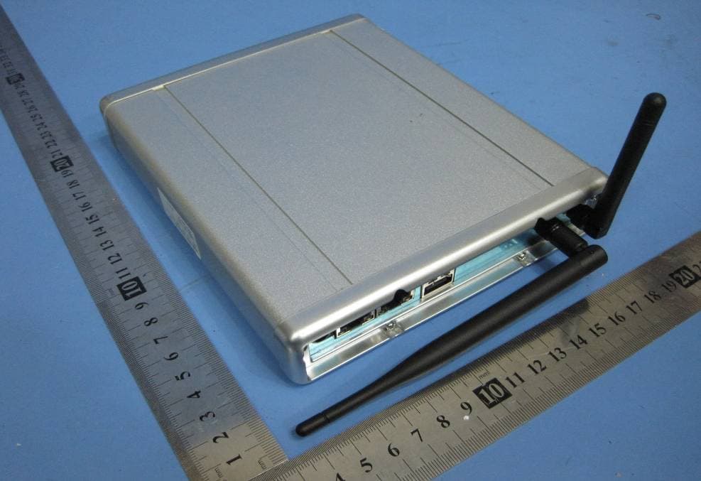
OU4-XG1000S-W
Jun 27, 2010WIFI GATEWAY
Equipment Class
DSC - Part 15 Security/Remote Control Transmitter
OU4-XCB80-FA
Feb 21, 2010FIRST ALERT BRIDGE
Equipment Class
DXX - Part 15 Low Power Communication Device Transmitter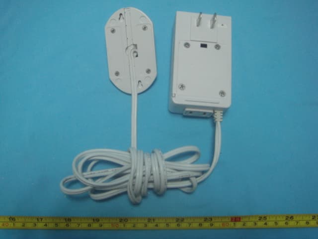
OU4XPC260
Mar 21, 2007LAMP DIMMER
Equipment Class
DSC - Part 15 Security/Remote Control Transmitter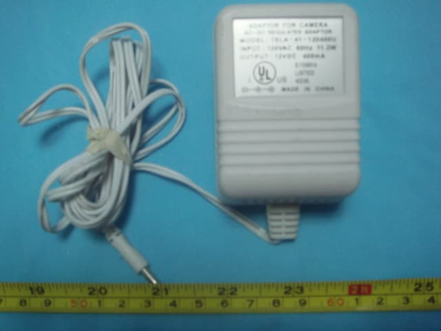
OU4XPC280
Mar 21, 2007GARAGE DOOR CONTROL
Equipment Class
DSC - Part 15 Security/Remote Control TransmitterOU4XG1000
Jul 12, 2006XANBOO REMOTE MONITORING AND ACCESS GATEWAY
Equipment Class
DSR - Part 15 Remote Control/Security Device Transceiver