OU4-XCB80-FAFIRST ALERT BRIDGE
Xanboo, Inc.
Click to zoom
Application Details
- Equipment Class
- DXX - Part 15 Low Power Communication Device Transmitter
- Date of Grant
- Feb 21, 2010
- Application Purpose
- Original Equipment
- Date of Application
- Feb 21, 2010
- Equipment Note
- FIRST ALERT BRIDGE
- Frequency Range
- 909.00000000 - 923.00000000
- Company
- Xanboo, Inc.
- Country
- United States
Documents & Files
Document Text
Text extracted from the exhibit documents filed with the FCC. Open a document above to read the original.
Users Manual
2 I OneLink Bridge Set Up/Discovey Please use the following directions to install and configure your OneLink Bridge. 1. To Power unit, connect transformer to OneLink Bridge and then plug transformer into wall outlet (120VAC). 2. Log into your Remote Account and got to the Discovery page of the Account Settings section. Press the “Start Discovery” button on the Discovery page. 3. Once the Discovery process has begun, press the Discovery button on the OneLink Bridge. Note: You only have 2 minutes once the Bridge enters into the Discovery mode. 4. Once the Discovery process has finished for the OneLink Bridge, it will appear on the list of your devices on the Discovery page. OneLink Device Discovery 1. While you are in Discovery mode the top light will be flashing. 2. Press down the test button on any one of the OneLink Alarms in your system, until the flashing LED on the OneLink bridge stops flashing. 3. When you are finished discovering devices, press “Stop Discovery” and click “Device Overview”. 4. At a later date, if you wish to add additional OneLink Alarms devices to your system, simply log into your Remote Account and go to the Discovery page of the Account Settings section; press the “Start Discovery” button on the Discovery page and repeat steps 2 and 3 above. This Device Complies With Part 15 of The FCC Rules. Operation is subject to the following two conditions: (1) this device may not cause harmful interference, and (2) this device must accept any interference received, including interference that may cause undesired operation. FCC NOTE: THE MANUFACTURER IS NOT RESPONSIBLE FOR ANY RADIO OR TV INTERFERENCE CAUSED BY UNAUTHORIZED MODIFICATIONS TO THIS EQUIPMENT. SUCH MODIFICATIONS COULD VOID THE USER’S AUTHORITY TO OPERATE THE EQUIPMENT. START DISCOVERY ONELINK BRIDGE DISCOVERED DISCOVERY IN PROGRESS ONELINK TEST BUTTON DC POWER DISCOVERY BUTTON
Cover Letter(s)
Xanboo, Inc. FCC ID:OU4 -XCB80-FA POWER OF ATTORNEY Jan 29,2010 Federal Communications Commission Authorization and Evaluation Division 7435 Oakland Mills Road Columbia, MD 21046 To Whom It May Concern: We, the undersigned, hereby authorize Waltek Services (ShenZhen) Co., Ltd. (Philo Zhong) on our behalf, to apply to the Federal Communications Commission on our equipment. Any and all acts carried out by Waltek Services (ShenZhen) Co., Ltd. (Philo Zhong) on our behalf shall have the same effect as acts of our own. This authorization expires on Jan 30, 2011. This is to advise that we are in full compliance with the Anti-Drug Abuse Act. We, Xanboo, Inc., are not subject to a denial of federal benefits pursuant to Section 5301 of the Anti-Drug Act of 1988, 21 USC853a, and no party to the application is subject to a denial of federal benefits pursuant to that section. Sincerely, Xanboo, Inc. ------------------------------- Sr. RF Engineer
External Photos
Xanboo, Inc. FCC ID: OU4-XCB80-FA Page 28 of 34 12 Photographs - Constructional Details 12.1 EUT - Front View 12.2 EUT - Back View Xanboo, Inc. FCC ID: OU4-XCB80-FA Page 29 of 34 12.3 EUT - Front View 12.4 EUT - Back View
ID Label/Location Info
Xanboo, Inc. FCC ID: OU4-XCB80-FA Page 33 of 33 13 FCC ID Label This device complies with Part 15 of the FCC Rules. Operation is subject to the following two conditions: (1) this device may not cause harmful interference, and (2) this device must accept any interference received, including interference that may cause undesired operation The Label must not be a stick-on paper. The Label on these products must be permanently affixed to the product and readily visible at the time of purchase and must last the expected lifetime of the equipment not be readily detachable. Proposed Label Location on EUT EUT Bottom View/proposed FCC Mark Location FCC ID:OU4-XCB80-FA This device complies with Part 15 of the FCC Rules. Operation is subject to the following two conditions: (1) this device may not cause harmful interference, and (2) this device must accept any interference received, including interference that may cause undesired operation
ID Label/Location Info
FCC ID Label Sample for Model XCB80-FA FCC ID : OU4-XCB80-FA This device complies with Part 15 of the FCC Rules. Operation is subject to the following two conditions:(1)this device may not cause harmful interference, and (2) this device must accept any interference received, including interference that may cause undesired operation.
Internal Photos
2.1 PCB1 - Front View 2.2 PCB1 - Back View 2.3 PCB2 - Front View 2.4 PCB2 - Back View 2.5 PCB3 - Front View 2.6 PCB3 - Back View
Operational Description
XCB80-FA First Alert Bridge The hardware architecture is shown in Figure 1. 1 The unit includes two RF module, one is 418MHz RX module, and the other is 900MHz TX module. The 418 MHz RF module is comprised of two chip, the transceiver chip CC1000, and the baseband chip PIC16LF628 which osc is 26.00MHz. The baseband chip is firmware the protocol, drive CC1000 to receive data from antenna. And the 900MHz TX module transmits the data from 418MHz RX module. 2 The MCU (PIC18F6722) deal with kinds of operation,the osc is 4.00MHz including scanning the discovery switch to initialize communication, monitoring the battery voltage, detecting contact event, flashing the LED to indicate the unit status, and so on.
Test Report
Xanboo, Inc. FCC ID: OU4-XCB80-FA FCC TEST REPORT Page 1 of 36 FCC ID : OU4-XCB80-FA Applicant : Xanboo, Inc. Address : 400 Columbus Ave. Valhalla New York United States Equipment Under Test (EUT) : Product description : First Alert Bridge Model No. : XCB80-FA Modulation : FSK Standards : FCC 15 Paragraph 15.249 Date of Test : Jan. 29,2010 Project Engineer : Olic.huang Reviewed By : Prepared By: Waltek Services (Shenzhen) Co., Ltd. 1/F, Fukangtai Building, West Baima Rd., Songgang Street, Baoan District, Shenzhen 518105, China Tel :+86-755-27553488 Fax:+86-755-27553868 Xanboo, Inc. FCC ID: OU4-XCB80-FA Page 2 of 36 2 Contents Page 1 COVER PAGE ......................................................................................................................................................... 1 2 CONTENTS .............................................................................................................................................................. 2 3 TEST SUMMARY ................................................................................................................................................... 4 4 GENERAL INFORMATION.................................................................................................................................. 5 4.1 CLIENT INFORMATION........................................................................................................................................ 5 4.2 GENERAL DESCRIPTION OF E.U.T....................................................................................................................... 5 4.3 DETAILS OF E.U.T. ............................................................................................................................................. 5 4.4 DESCRIPTION OF SUPPORT UNITS....................................................................................................................... 5 4.5 STANDARDS APPLICABLE FOR TESTING.............................................................................................................. 5 4.6 TEST FACILITY.................................................................................................................................................... 6 4.7 TEST LOCATION.................................................................................................................................................. 6 5 EQUIPMENT USED DURING TEST ................................................................................................................... 7 6 CONDUCTED EMISSION TEST .......................................................................................................................... 8 6.1 TEST EQUIPMENT................................................................................................................................................ 8 6.2 TEST PROCEDURE............................................................................................................................................... 8 6.3 CONDUCTED TEST SETUP................................................................................................................................... 9 6.4 EUT OPERATING CONDITION............................................................................................................................. 9 6.5 CONDUCTED EMISSION LIMITS......................................................................................................................... 10 6.6 CONDUCTED EMISSION TEST RESULT............................................................................................................... 10 6.7 CONDUCTED EMISSION TEST SETUP VIEW........................................................................................................ 12 7 RADIATION EMISSION TEST........................................................................................................................... 13 7.1 TEST EQUIPMENT.............................................................................................................................................. 13 7.2 MEASUREMENT UNCERTAINTY......................................................................................................................... 13 7.3 TEST PROCEDURE............................................................................................................................................. 13 7.4 RADIATED TEST SETUP..................................................................................................................................... 14 7.5 SPECTRUM ANALYZER SETUP........................................................................................................................... 14 7.6 CORRECTED AMPLITUDE & MARGIN CALCULATION........................................................................................ 15 7.7 SUMMARY OF TEST RESULTS............................................................................................................................ 15 7.8 EUT OPERATING CONDITION........................................................................................................................... 16 7.9 RADIATED EMISSIONS LIMIT............................................................................................................................ 16 7.10 RADIATED EMISSIONS TEST RESULT................................................................................................................ 17 8 PERIODIC OPERATION..................................................................................................................................... 21 9 ANTENNA REQUIREMENT............................................................................................................................... 24 10 20-DB BANDWIDTH............................................................................................................................................. 24 11 BAND EDGE ............…
Text truncated - open the document above for the full version.
Test Setup Photos
2.1 Radiation Emission Test View For 30MHz-1000MHz 2.2 Radiation Emission Test View For 1GHz-10GHz 2.3 Conducted Emission Test Setup View
Contact Information
Applicant
Kent E Britain(Sr. RF Engineer)
Test Firm
Waltek Services(Shenzhen) Co., Ltd.Philo zhong
Technical Specifications
| # | Rule Parts | Frequency Range | Power Output |
|---|---|---|---|
| 1 | 15C | 909 MHz - 923 MHz | - |
Other Applications from Xanboo, Inc.
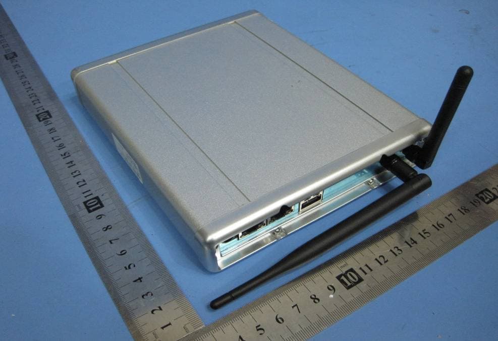
OU4-XG1000S-W
Jun 27, 2010WIFI GATEWAY
Equipment Class
DSC - Part 15 Security/Remote Control Transmitter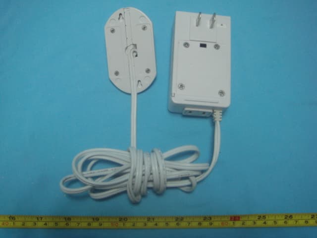
OU4XPC260
Mar 21, 2007LAMP DIMMER
Equipment Class
DSC - Part 15 Security/Remote Control Transmitter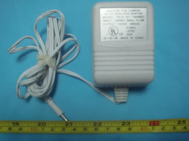
OU4XPC280
Mar 21, 2007GARAGE DOOR CONTROL
Equipment Class
DSC - Part 15 Security/Remote Control TransmitterOU4XG1000
Jul 12, 2006XANBOO REMOTE MONITORING AND ACCESS GATEWAY
Equipment Class
DSR - Part 15 Remote Control/Security Device Transceiver
OU4-XRT750
May 10, 2005Repeater for Wireless Sensors
Equipment Class
DSR - Part 15 Remote Control/Security Device Transceiver