OU4-XG1000S-WWIFI GATEWAY
Xanboo, Inc.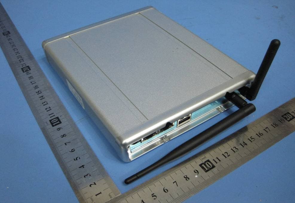
Click to zoom
Application Details
- Equipment Class
- DSC - Part 15 Security/Remote Control Transmitter
- Date of Grant
- Jun 27, 2010
- Application Purpose
- Original Equipment
- Date of Application
- Jun 27, 2010
- Equipment Note
- WIFI GATEWAY
- Frequency Range
- 418.92000000 - 418.92000000
- Company
- Xanboo, Inc.
- Country
- United States
Documents & Files
Document Text
Text extracted from the exhibit documents filed with the FCC. Open a document above to read the original.
Users Manual
STEP 2 STEP 3 STEP 1 FOR MORE INFORMATION PLEASE VISIT: http://www.myremotemanager.com FOR ASSISTANCE, PLEASE CALL: 1.888.889.5211 DISCOVER DEVICES QUICK INSTALLATION GUIDE PLEASE FOLLOW THESE 3 SIMPLE STEPS TO QUICKLY GUIDE YOU THROUGH INSTALLATION OF YOUR MYREMOTEMANAGER SYSTEM MyRemoteManager CONTROLLER SETUP A. Hardware Installation Connect the XG1000S-W Controller to a free port on your router or home network device with provided Cat5 Ethernet cable, plug into AC power outlet, and then power up Controller. Connect Camera to your network with a CAT 5 Ethernet cable and plug into AC power outlet. If there are not enough open ports on your router a network hub or switch may be connected to your router to provide more ports. NOTE: Camera discovery must take place with your Camera(s) wired to your network. CONGRATULATIONS! YOU HAVE REGISTERED & INSTALLED YOUR XG1000S-W CONTROLLER! YOU ARE NOW FULLY ABLE TO BE THERE, EVEN WHEN YOU’RE NOT! CAMERA AND DEVICE DISCOVERY IN PROGRESS DOOR SENSOR [INCLUDED] ACCESSORIES 2 ROUTER (NOT INCLUDED) INTERNET XG1OOOS-W CONTROLLER DSL/CABLE MODEM (NOT INCLUDED) WIFI IP CAMERA 1 34 LANLANWAN B. Login Using a PC on the same local network as your Controller, access http://myremotemanager.com through a web browser. Enter the User ID and Password, you created when you purchased the system, in the proper fields and log in to your MyRemoteManager account as shown below. B. Controller Registration Once logged into your account, navigate to the (A) ‘ACCOUNT SETTINGS’, then (B) ‘DISCOVERY’ and click (C) New Location Button, as shown below, to register your Controller to your account. The Controller registration Wizard will prompt you to download the plug-in needed to complete this process. When complete click on the ‘CONTINUE WITH DEVICE DISCOVERY’ link. MOBILE APPLICATION B C A You can access the system from just about anywhere with a web-enabled cell phone. Just use your phone’s web browser to download and install the application from http://myremotemanager.com/mobile/j2me (with a JAVA enabled phone) or from http://myremotemanager.com/mobile (if your phone is not JAVA enabled) and enter your remote account User ID & Password. From an iPhone, using the browser, navigate to http://myremotemanager.com and you will be brought to a website specially designed for the iPhone. This device complies with Part 15 of the FCC Rules. Operation is subject to the following two conditions: (1) this device may not cause harmful interference, and (2) this device must accept any interference received, including interference that may cause undesired operation. FCC NOTE THE MANUFACTURER IS NOT RESPONSIBLE FOR ANY RADIO OR TV INTERFERENCE CAUSED BY UNAUTHORIZED MODIFICATIONS TO THIS EQUIPMENT. SUCH MODIFICATIONS COULD VOID THE USER’S AUTHORITY TO OPERATE THE EQUIPMENT. The Discovery process should start automatically. If you don't see a message that Discovery is initializing or in progress, press the Start Discovery Button to start the Discovery process. After the message changes to ‘DISCOVERY IN PROGRESS...’ your WiFi Cameras will automatically discover to your controller. After Discovery, you must remove Cat-5 cable and power cycle Camera to switch to WiFi mode. To discover other devices, press the appropriate Discovery Button on the device as shown below. WIFI CAMERA Contains WiFi Module FCC ID: VOEWL0118 The antenna requirement: 1. Frequency Range: 2.4~2.5 GHz 2. Impedance: 50 Ohms 3. VSWR: ≦2.0dB 4. Gain: 5.0dBi 5. Admitted power radiation: 1W 6. Type: Toroidal 7. Radiation: Omni 8. Connecter Type: SMA 9. Cable: RG-178, 50 Ohm 10. Operation temperature range: -20°C~ +70°C 11. Storage temperature range: -30°C~ +80°C FCC RF Exposure compliance: The antenna(s) used for this transmitter must be installed to provide a separation distance of at least 20cm from all persons and must not be collocated or operating in conjunction with any other antenna or transmitter. This device complies with Part 15 of the FCC Rules. Operation is subject to the following two conditions: (1)This device may not cause harmful interference, and (2)This device must accept any interference received, including interference that may cause undesired operation. Federal Communications Commission (FCC) Statement This equipment has been tested. And it found to comply with the limits for a Class B digital device pursuant to Part 15 of the FCC Rules. These limits are designed to provide reasonable protection against harmful interference in a residential installation. This equipment generates and uses and radiates radio frequency energy and, if not installed and used in accordance with the instruction, may cause harmful interference to radio communications. However, there is no guarantee that interference will not occur in a particular installation. If this equipment does cause harmful interference to radio or television reception, which can be determined by turning the equipment off and on, the user is encouraged to try to correct the interference by one or more of the following measures: - Reorient or relocate the receiving antenna. - Increase the separation between the equipment and receiver. - Connect the equipment into an outlet on a circuit different from that to which the receiver is connected - Consult the dealer or an experienced radio /TV technician for help. Warning: A shielded-type power cord is required in order to meet FCC emission limits and also to prevent interference to the nearby radio and television reception. It is essential that only the supplied power cord be used. NOTE: The manufacturer is not responsible for any radio or TV interference caused by unauthorized modifications to this equipment. Such modifications could void the user’s authority to operate the equipment. Warning: Antenna will be used only which was described in appendix, any other type is prohibited! Antenna must be installed by technical worker, can not be installed or changed by users.
Block Diagram
Figure 1. XG1000S-W Block Diagram 10/100 MACs GPIO GPIO PCI Interface Real time Clock I2C,SPI interface DMA USB Host & AC97 Controller Time/WDT/Reset Interrupt SRAM Controller NOR flash NAND flash SDRAM Keypad LED AFM2 Code Tranceiver Ethernet PHY LAN2 10/100 Base-T 418MHz Antenna RTC EEPROM Controller Controller USB 2.0 USB Device controller RF 5V DC 3.3V Regulator 1.8V Regulator contorller MIPS-32 CPU Core AU1550 Ethernet PHY LAN1 10/100 Base-T GPIO CC1000 PIC16lF628 MiNi PCI Socket For 2.4GHz Antenna 802.11 b/g WLAN Card 25MHz 4MHz 11.0592MHz 32.768MHz 12MHz 25MHz
Cover Letter(s)
Xanboo Inc FCC ID: OU4-XG1000S-W Contains WiFi Module FCC ID: VOEWL0118 cover letter The EUT is : WiFi Gateway, model no.: XG1000S-W, Contains WiFi Module FCC ID: VOEWL0118, all the test items was complies with the limits found in FCC Part 15B and 15C. For more details of the test result, please refer to the report of FCC ID: VOEWL0118 and FCC ID: OU4-XG1000S-W。 PERPARED BY: Waltek Services (Shenzhen) Co., Ltd. 1/F, Fukangtai Building,West Baima Rd.,Songgang Street, Baoan District, Shenzhen 518105,China Tel: 86-755-27553488 Fax: 86-755-27553868
Cover Letter(s)
Xanboo, Inc. FCC ID: OU4-XG1000S-W POWER OF ATTORNEY June 09,2010 Federal Communications Commission Authorization and Evaluation Division 7435 Oakland Mills Road Columbia, MD 21046 To Whom It May Concern: We, the undersigned, hereby authorize Waltek Services (ShenZhen) Co., Ltd. (Philo Zhong) on our behalf, to apply to the Federal Communications Commission on our equipment. Any and all acts carried out by Waltek Services (ShenZhen) Co., Ltd. (Philo Zhong) on our behalf shall have the same effect as acts of our own. This authorization expires on June 10, 2011. This is to advise that we are in full compliance with the Anti-Drug Abuse Act. We, Xanboo, Inc., are not subject to a denial of federal benefits pursuant to Section 5301 of the Anti-Drug Act of 1988, 21 USC853a, and no party to the application is subject to a denial of federal benefits pursuant to that section. Sincerely, Xanboo, Inc. ------------------------------- Sr. RF Engineer
Cover Letter(s)
Xanboo Inc June 18, 2010. Request for Modular Approval Attestation for the WiFi Module (FCC ID: VOEWL0118) Per the Part 15.212 of the FCC Rules for Part 15 Unlicensed Modular Transmitter approval the following information is provided: 1) “The modular transmitter must have it’s own shield.” There is shield present on the PCB, covering the section of WiFi. Only the RF Antenna is exposed outside the shielding. 2) “The modular transmitter must have buffered modulation/data inputs”. Input signal buffered by the IC (RT2527-48P). 3) “The modular transmitter must have it’s own power supply regulation.” The module does not have it’s own power supply, so that the regulated power of 3.3V is supplied from the end product. 4) “The modular transmitter must comply with the antenna requirements of Section 15.203 and 15.204(c).” The antenna of the device used was display in appendix antenna information, in other words, only this antenna can be used. 5) Any antenna used with the module must be approved with the module. (The “professional installation” provision (15.203) may not be applied to modules) 6) “The modular transmitter must be tested in a stand-alone configuration, i.e., must not be inside another device during testing.” The Module was tested as a standalone device, not inside any other equipment. 7) Unless the module is battery powered, it must comply with the AC line conducted requirements found in Section 15.207. 8) AC, DC, and data input/output lines must not contain ferrites, unless they will be marketed with the module. 9) The modular transmitter will be labeled with the FCC ID: VOEWL0118, and, if the FCC ID is not visible when the module is installed inside another device, then the outside of the device into which the module is installed must also display a label referring to the enclosed module. This exterior FCC ID Label will use wording, “Contains WiFi Module FCC ID: VOEWL0118”. 10)“The modular transmitter must comply with any specific rule or operating requirements applicable to the transmitter and the manufacturer must provide adequate instructions...” The necessary explanations to comply with this requirement are contained in the manual.
External Photos
2.1 EUT - Front View 2.2 EUT - Back View
ID Label/Location Info
FCC ID Label This device complies with Part 15 of the FCC Rules. Operation is subject to the following two conditions:(1)this device may not cause harmful interference,and (2) this device must accept any interference received, including interference that may cause undesired operation. The Label must not be a stick-on paper. The Label on these products must be permanently affixed to the product and readily visible at the time of purchase and must last the expected lifetime of the equipment not be readily detachable. Proposed Label Location on EUT EUT Bottom View/proposed FCC Label Location FCC ID: OU4-XG1000S-W This device complies with Part 15 of the FCC Rules. Operation is subject to the following two conditions:(1)this device may not cause harmful interference,and (2) this device must accept any interference received, including interference that may cause undesired operation
ID Label/Location Info
Interior FCC ID Label Sample for FCC ID: VOEWL0118_ FCC ID: VOEWL0118
Internal Photos
2.1 PCB1-Front View 2.2 PCB1-Back View 2.3 PCB2-Front View 2.4 PCB2-Back View 2.5 PCB3-Front View 2.6 PCB3-Back View
Operational Description
XG1000S-W Architecture WiFi Gateway hardware architecture is shown in Figure 1. It is based on the microprocessor Au1550 which is a versatile high-performance, low-power, high integration security network system-on-a-chip (SOC) designed for wired and wireless applications where security is important. This security network processor accelerates networking applications such as gateways and network addressable storage (NAS) units, wireless access points, and voice over internet Protocol environments. The network processor is a complete SOC based on the MIPS32 instruction set and runs at Linux operating system. It integrate a variety of periphery interface, including interrupt control, DMA controller, PCI interface, USB host, I2C, SPI, SRAM controller, DDR/SDR SDRAM controller, UART, 10/100 Ethernet MAC,GPIO, 32-Bit PCI interface and so on. CC1000 is a true single chip UHF transceiver designed for very low power and low voltage wireless communications with sensors. It operates at 418MHz frequency by programmed different firmware via an easy-to-interface serial bus with a microcontroller. This device is embedded a 802.11b/g PCIe Mini Card network adapter operating in the 2.4GHz radiated frequency.
Schematics
S H E E T OF SIZE FILE B TITLE SUPERSEDESDRAWING NO. 1 2 3 4 ABCD ABCD 1 2 3 4 SEE SHEET 1 FOR NOTES AND APPROVALS PRINT DATE TIME 115 West 30th Street 6th FL., New York, NY 10001 (646) 674 - 3000 BOO THIS DOCUMENT AND THE DATA DISCLOSED HEREIN OR HEREWITH IS THE PROPERTY OF XANBOO AND IS NOT TO BE REPRODUCED, USED OR DISCLOSED IN WHOLE OR IN PART WITHOUT THE PERMISSION OF XANBOO. AL L PATENT, PROPRIETARY, DESIGN, USE, SALE, MANUFACTURING AND REPRODUCTION RIGHTS THERETO ARE RESERVED BY XANBOO. 12 XAN0408 Rev1.4-02 XAN0408_1_4 2004-01-14 10:07:24 CC1000 AGND 2 RF_IN 3 RF_OUT 4 AVDD 5 AGND 6 AGND 7 AVDD 9 L1 10 AVDD 1 DGND 20 DVDD 21 DGND 22 DIO 23 DCLK 24 PCLK 25 PDATA 26 PALE 27 RSSI/IF 28 L2 11 CHP_OUT 12 R_BIAS 13 AGND 14 AVDD 15 AGND 16 XOSC_Q2 17 XOSC_Q1 18 AGND 8 AGND 19 U1 CC1000 XL4 33nH, 5% +3.3V R131 82k +3.3V XX1 11.0592 Mhz C141 16pF C15116pF C15 1nF C2220pF C14 220pF C13 220pF C12 1nF C11 1nF C10 33nF XL268nH XL36.2nH XC5 8.2pF +3.3V XC3 15pF XC4 5.6pF L2BLM11A102S RSSI R1TBA C4TBA XL1 8.2nH XC122pF XC215pF LOW PASS FILTER NOT FITTED C3TBA 433MHz XAN0408_1_4 TKS2351CT-ND PALEPDATAPCLKDCLKDIO C131 4.7pF + C13.3uF C1733nF ANT S H E E T OF SIZE FILE B TITLE SUPERSEDESDRAWING NO. 1 2 3 4 ABCD ABCD 1 2 3 4 SEE SHEET 1 FOR NOTES AND APPROVALS PRINT DATE TIME 115 West 30th Street 6th FL., New York, NY 10001 (646) 674 - 3000 BOO THIS DOCUMENT AND THE DATA DISCLOSED HEREIN OR HEREWITH IS THE PROPERTY OF XANBOO AND IS NOT TO BE REPRODUCED, USED OR DISCLOSED IN WHOLE OR IN PART WITHOUT THE PERMISSION OF XANBOO. AL L PATENT, PROPRIETARY, DESIGN, USE, SALE, MANUFACTURING AND REPRODUCTION RIGHTS THERETO ARE RESERVED BY XANBOO. 22 XAN0408 Rev1.4-02 XAN0408_1_4 2004-01-14 10:06:51 MICROCONTROLLER C5 0.1uF Y1 4Mhz C6 33pF C7 33pF PIC_VCC RF_DATARF_BUSYRF_RXRF_TX R24.7K R4000 R31K LED1GREEN RF_RTSRF_CTS +3.3V MCLR2DIAG PIC_VCC RA2/AN2/Vref 1 RA3/AN3/CMP1 2 RA4/TOCKI/CMP2 3 RA5/MCLR/THV 4 Vss 5 RB0/INT 7 RB1/RX/DT 8 RB2/TX/CK 9 RB3/CCP1 10 RB4/PGM 11 RB5 12 RB6/T1OSO/T1CKI 13 RB7/T1OSI 14 VDD 15 RA6/OSC2/CLKOUT 17 RA7/OSC1/CLKIN 18 RA0/AN0 19 RA1/AN1 20 Vss 6 VDD 16 U2PIC16LF628 XAN0408_1_4 R5100k PIC_VCC D1 DIO5711WS MCLR2 VPP 1234567891011 P1CON11 RSSI DCLKPDATAPCLKPALEDIO RF_RXRF_TXDIAGRF_BUSYRF_DATARF_RTSRF_CTS
Test Report
Xanboo Inc FCC ID: OU4-XG1000S-W FCC TEST REPORT Ref. No: WT10041228-S-E-F Page 1 of 36 FCC ID : OU4-XG1000S-W Applicant : Xanboo Inc Address of Applicant : 400 Columbus Ave. Valhalla New York United States Equipment Under Test (EUT) : Product description : WiFi Gateway Model No. : XG1000S-W Standards : FCC 15 Subpart C Paragraph 15.231 Date of Test : June 09,2010 Test Engineer :Olic huang Reviewed By : PERPARED BY: Waltek Services (Shenzhen) Co., Ltd. 1/F, Fukangtai Building,West Baima Rd.,Songgang Street, Baoan District, Shenzhen 518105,China Tel: 86-755-27553488 Fax: 86-755-27553868 Xanboo Inc FCC ID: OU4-XG1000S-W Ref. No: WT10041228-S-E-F Page 2 of 36 2 Contents Page 1 COVER PAGE..........................................................................................................................................................1 2 CONTENTS ..............................................................................................................................................................2 3 TEST SUMMARY....................................................................................................................................................4 4 GENERAL INFORMATION..................................................................................................................................5 4.1 CLIENT INFORMATION............................................................................................................................................5 4.2 GENERAL DESCRIPTION OF E.U.T...........................................................................................................................5 4.3 DETAILS OF E.U.T. .................................................................................................................................................5 4.4 DESCRIPTION OF SUPPORT UNITS...........................................................................................................................5 4.5 STANDARDS APPLICABLE FOR TESTING..................................................................................................................5 4.6 TEST FACILITY........................................................................................................................................................6 4.7 TEST LOCATION......................................................................................................................................................6 5 EQUIPMENT USED DURING TEST ...................................................................................................................7 6 CONDUCTED EMISSION TEST ..........................................................................................................................8 6.1 TEST EQUIPMENT....................................................................................................................................................8 6.2 TEST PROCEDURE...................................................................................................................................................8 6.3 CONDUCTED TEST SETUP.......................................................................................................................................9 6.4 EUT OPERATING CONDITION.................................................................................................................................9 6.5 CONDUCTED EMISSION LIMITS.............................................................................................................................10 6.6 CONDUCTED EMISSION TEST DATA......................................................................................................................10 6.7 CONDUCTED EMISSION TEST SETUP VIEW............................................................................................................12 6.7.1 Test Setup Front View for the wireless mode. ............................................................................................12 6.7.2 Test Setup Back View for the wireless mode. .............................................................................................12 6.7.3 Test Setup Front View for the PC mode. ....................................................................................................13 6.7.4 Test Setup Back View for the PC mode. .....................................................................................................13 7 RADIATION EMISSION TEST...........................................................................................................................14 7.1 TEST EQUIPMENT..................................................................................................................................................14 7.2 MEASUREMENT UNCERTAINTY.............................................................................................................................14 7.3 TEST PROCEDURE.................................................................................................................................................14 7.4 RADIATED TEST SETUP.........................................................................................................................................15 7.5 SPECTRUM ANALYZER SETUP...............................................................................................................................15 7.6 CORRECTED AMPLITUDE & MARGIN CALCULATION............................................................................................16 7.7 SUMMARY OF TEST RESULTS................................................................................................................................16 7.8 EUT OPERATING CONDITION...............................................................................................................................17 7.9 RADIATED EMISSIONS LIMIT......................................................................................…
Text truncated - open the document above for the full version.
Test Setup Photos
Conducted Emission Test Setup View Test Setup Front View for the wireless mode. Test Setup Back View for the wireless mode. Test Setup Front View for the PC mode. Test Setup Back View for the PC mode. Radiation Emission Test View For 30MHz-1000MHz for PC mode Radiation Emission Test View For 30MHz-1000MHz for wireless mode Radiation Emission Test View For 1GHz-5GHz
Contact Information
Applicant
Kent E Britain(Sr. RF Engineer)
Test Firm
Waltek Services(Shenzhen) Co., Ltd.Philo zhong
Technical Specifications
| # | Rule Parts | Frequency Range | Power Output |
|---|---|---|---|
| 1 | 15.231 | 418.92 MHz - 418.92 MHz | - |
Other Applications from Xanboo, Inc.

OU4-XCB80-FA
Feb 21, 2010FIRST ALERT BRIDGE
Equipment Class
DXX - Part 15 Low Power Communication Device Transmitter
OU4XPC260
Mar 21, 2007LAMP DIMMER
Equipment Class
DSC - Part 15 Security/Remote Control Transmitter
OU4XPC280
Mar 21, 2007GARAGE DOOR CONTROL
Equipment Class
DSC - Part 15 Security/Remote Control TransmitterOU4XG1000
Jul 12, 2006XANBOO REMOTE MONITORING AND ACCESS GATEWAY
Equipment Class
DSR - Part 15 Remote Control/Security Device Transceiver
OU4-XRT750
May 10, 2005Repeater for Wireless Sensors
Equipment Class
DSR - Part 15 Remote Control/Security Device Transceiver