OU4XPC260LAMP DIMMER
Xanboo, Inc.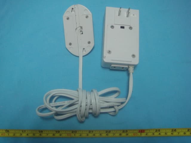
Click to zoom
Application Details
- Equipment Class
- DSC - Part 15 Security/Remote Control Transmitter
- Date of Grant
- Mar 21, 2007
- Application Purpose
- Original Equipment
- Date of Application
- Mar 21, 2007
- Equipment Note
- LAMP DIMMER
- Frequency Range
- 418.00000000 - 418.00000000
- Company
- Xanboo, Inc.
- Country
- United States
Documents & Files
Document Text
Text extracted from the exhibit documents filed with the FCC. Open a document above to read the original.
Users Manual
Lamp Dimmer Installation notes The Lamp dimmer is designed to work with all incandescent (Tungsten loads) of up to 300W. Plug the unit in the wall outlet. Plug the lamp in the module Use the tethered device to control the lamp brightness Lamp and Wall Dimmer User Operation The dimmer dongle is used to manually adjust and control lighting. There are two buttons on the dongle. The button with the raised bump is the lights on or ramp brightness level up control. This raised button has a red back light to aid location of the buttons in the dark. The button with the lowered bump is the lights off or ramp brightness level down control. This button will is also backlit at a lower level. When power is applied to the dimmer, the dimmer level will default to the full on state. Pressing and holding the lights off button will ramp the light level down to off. Pressing and holding the lights on button will ramp the light level to full on. The light level set by pressing and holding either of these two buttons is the user's set level and will be remembered by the dimmer. If the user presses the lights off button, using a quick tap, the light level will be set to full off. If the user presses the lights on button, using a quick tap, the light level will be set to the last user's set level or 16% brightness using the brighter of these levels. The dimmer has a delayed off feature. This allows the light to be set on, then after a period of time, the light will be turned turn off. This is useful, at night, if the light control is located far from the room exit or as a sleep setting for reading in bed. To activate this feature press and hold either button and tap the other. The dimmer will beep and the light level will be set to the 50% brightness level if it was below the 50% level originally. The default on time will be 5 minutes. When this on time expires, the brightness level will be slowly ramped down to full off. During the on time, the brightness level may be changed, without disturbing the delayed off timer, by using the press and hold method to adjust the brightness level. The delayed turn off function has a snooze mode. This is activated by pressing either button during the slow off ramp. When the snooze mode is activated the brightness level will be ramped back to the original level and the delayed off timer will be restarted for another delayed turn off cycle. The delayed turn off function can be canceled if either button is tapped during the on time interval. Press the up arrow to make the lamp Brighter and the down arrow to make it dimmer. The Up arrow is the one pointing to the cord Once this is set you can tap the down arrow to turn the lamp off and the up arrow to turn it on. Warnings Ensure that the lamp load is incandescent (normal light bulbs). Do not use the dimmer with fluorescent or low voltage lamps that require a power adapter or transformer. The product should only be used indoors. Please ensure the product is used in a normally ventilated room. Do not cover or paint the product Set up and discovery RON/Arin/Babak Place your Boiler plate here Approvals FCC Part 15 (Arin place the FCC boiler plate here) UL 244A Specifications Voltage: 120V 60 Hz Power: 300W max (resistive, Incandescent, Tungsten only) Dimensions: Main unit: 3.5”Lx 2”Wx 1.5D The control unit: 3.25”Lx1.75”Wx0.75High This device complies with Part 15 of the FCC Rules. Operation is subject to the following two conditions: (1) this device may not cause harmful interference, and (2) this device must accept any interference received, including interference that may cause undesired operation. FCC NOTE: The manufacturer is not responsible for any radio or TV interference caused by unauthorized modifications to this equipment. Such modifications could void the user's authority to operate the equipment.
Block Diagram
120V 120V PSU 418MHz
External Photos
EUT - Front View EUT - Back View
ID Label/Location Info
FCC ID Label Sample for Model: XPC260 FCC ID: OU4XPC260 This device complies with Part 15 of the FCC Rules. Operation is subject to the following two conditions: (1) This device may not cause harmful interference, and (2) This device must accept any interference received, including interference that may cause undesired operation.
ID Label/Location Info
FCC ID Label This device complies with Part 15 of the FCC Rules. Operation is subject to the following two conditions:(1)this device may not cause harmful interference, and (2) this device must accept any interference received, including interference that may cause undesired operation The Label must not be a stick-on paper. The Label on these products must be permanently affixed to the product and readily visible at the time of purchase and must last the expected lifetime of the equipment not be readily detachable. Proposed Label Location on EUT EUT Bottom View/proposed FCC Mark Location FCC ID:OU4XPC260 This device complies with
Internal Photos
PCB1-Front View PCB1-Back View PCB2-Front View PCB2-Back View PCB3-Front View PCB3-Back View
Operational Description
Lamp Dimmer Jan 25, 2007 XANBOO’s Lamp dimmer accessory enables you to signal an audible alert to an event being monitored. If, for example, you are monitoring an area for motion and this is detected, the siren can be configured to sound when the area event takes place. Feature: 1. Two way telemetry link to support XANBOO AFM2 functionality. 2. Corded design removes the need for external power supply. 3. LED indicates state of available power to device. 4. Discovery button. 5. Sound level 105dB. 6. Typical range outdoors: 250 feet. 7. Typical range indoors: 60 feet. 8. Transmits on 418MHz frequency. 7. Input: 120V 60Hz AC
Schematics
S H E E T OF SIZE FILE B TITLE SUPERSEDESDRAWING NO. 1 2 3 4 ABCD ABCD 1 2 3 4 SEE SHEET 1 FOR NOTES AND APPROVALS PRINT DATE TIME 115 West 30th Street 6th FL., New York, NY 10001 (646) 674 - 3000 BOO THIS DOCUMENT AND THE DATA DISCLOSED HEREIN OR HEREWITH IS THE PROPERTY OF XANBOO AND IS NOT TO BE REPRODUCED, USED OR DISCLOSED IN WHOLE OR IN PART WITHOUT THE PERMISSION OF XANBOO. AL L PATENT, PROPRIETARY, DESIGN, USE, SALE, MANUFACTURING AND REPRODUCTION RIGHTS THERETO ARE RESERVED BY XANBOO. 12 XAN0408 Rev1.4-02 XAN0408_1_4 2004-01-14 10:07:24 CC1000 AGND 2 RF_IN 3 RF_OUT 4 AVDD 5 AGND 6 AGND 7 AVDD 9 L1 10 AVDD 1 DGND 20 DVDD 21 DGND 22 DIO 23 DCLK 24 PCLK 25 PDATA 26 PALE 27 RSSI/IF 28 L2 11 CHP_OUT 12 R_BIAS 13 AGND 14 AVDD 15 AGND 16 XOSC_Q2 17 XOSC_Q1 18 AGND 8 AGND 19 U1 CC1000 XL4 33nH, 5% +3.3V R131 82k +3.3V XX1 11.0592 Mhz C141 16pF C15116pF C15 1nF C2220pF C14 220pF C13 220pF C12 1nF C11 1nF C10 33nF XL268nH XL36.2nH XC5 8.2pF +3.3V XC3 15pF XC4 5.6pF L2BLM11A102S RSSI R1TBA C4TBA XL1 8.2nH XC122pF XC215pF LOW PASS FILTER NOT FITTED C3TBA 433MHz XAN0408_1_4 TKS2351CT-ND PALEPDATAPCLKDCLKDIO C131 4.7pF + C13.3uF C1733nF ANT S H E E T OF SIZE FILE B TITLE SUPERSEDESDRAWING NO. 1 2 3 4 ABCD ABCD 1 2 3 4 SEE SHEET 1 FOR NOTES AND APPROVALS PRINT DATE TIME 115 West 30th Street 6th FL., New York, NY 10001 (646) 674 - 3000 BOO THIS DOCUMENT AND THE DATA DISCLOSED HEREIN OR HEREWITH IS THE PROPERTY OF XANBOO AND IS NOT TO BE REPRODUCED, USED OR DISCLOSED IN WHOLE OR IN PART WITHOUT THE PERMISSION OF XANBOO. AL L PATENT, PROPRIETARY, DESIGN, USE, SALE, MANUFACTURING AND REPRODUCTION RIGHTS THERETO ARE RESERVED BY XANBOO. 22 XAN0408 Rev1.4-02 XAN0408_1_4 2004-01-14 10:06:51 MICROCONTROLLER C5 0.1uF Y1 4Mhz C6 33pF C7 33pF PIC_VCC RF_DATARF_BUSYRF_RXRF_TX R24.7K R4000 R31K LED1GREEN RF_RTSRF_CTS +3.3V MCLR2DIAG PIC_VCC RA2/AN2/Vref 1 RA3/AN3/CMP1 2 RA4/TOCKI/CMP2 3 RA5/MCLR/THV 4 Vss 5 RB0/INT 7 RB1/RX/DT 8 RB2/TX/CK 9 RB3/CCP1 10 RB4/PGM 11 RB5 12 RB6/T1OSO/T1CKI 13 RB7/T1OSI 14 VDD 15 RA6/OSC2/CLKOUT 17 RA7/OSC1/CLKIN 18 RA0/AN0 19 RA1/AN1 20 Vss 6 VDD 16 U2PIC16LF628 XAN0408_1_4 R5100k PIC_VCC D1 DIO5711WS MCLR2 VPP 1234567891011 P1CON11 RSSI DCLKPDATAPCLKPALEDIO RF_RXRF_TXDIAGRF_BUSYRF_DATARF_RTSRF_CTS
Test Report
FCC TEST REPORT Page 1 of 29 FCC ID : OU4XPC260 Applicant : Xanboo Inc 115 West 30 th Street, 6 th Floor New York , NY10001 Equipment Under Test (EUT) : Product description : Lamp Dimmer Model No. : XPC260 Standards : FCC 15 Subpart C Paragraph 15.231 Date of Test : March 14, 2007 Test Engineer : Tiger Su Reviewed By : PERPARED BY: Waltek Services (Shenzhen) Co., Ltd. 8C,West Tower, Aidi Building, No.5003 Binhe Rd, Futian District, Shenzhen518045, Guangdong, China. Tel: 86-755-83551033 Fax: 86-755-83552400 Xanboo Inc FCC ID:OU4XPC260 Page 2 of 29 2 Contents Page 1 COVER PAGE..........................................................................................................................................................1 2 CONTENTS ..............................................................................................................................................................2 3 TEST SUMMARY....................................................................................................................................................5 4 GENERAL INFORMATION..................................................................................................................................6 4.1 CLIENT INFORMATION............................................................................................................................................6 4.2 GENERAL DESCRIPTION OF E.U.T...........................................................................................................................6 4.3 DETAILS OF E.U.T. .................................................................................................................................................6 4.4 DESCRIPTION OF SUPPORT UNITS...........................................................................................................................6 4.5 STANDARDS APPLICABLE FOR TESTING..................................................................................................................6 4.6 TEST FACILITY........................................................................................................................................................7 4.7 TEST LOCATION......................................................................................................................................................7 5 EQUIPMENT USED DURING TEST ...................................................................................................................8 6 CONDUCTED EMISSION TEST ..........................................................................................................................9 6.1 TEST EQUIPMENT....................................................................................................................................................9 6.2 TEST PROCEDURE...................................................................................................................................................9 6.3 CONDUCTED TEST SETUP.....................................................................................................................................10 6.4 EUT OPERATING CONDITION...............................................................................................................................10 6.5 CONDUCTED EMISSION LIMITS.............................................................................................................................11 6.6 CONDUCTED EMISSION TEST DATA......................................................................................................................12 6.7 CONDUCTIED EMISSIONS TEST DATA...................................................................................................................13 7 RADIATION EMISSION TEST...........................................................................................................................14 7.1 TEST EQUIPMENT..................................................................................................................................................14 7.2 MEASUREMENT UNCERTAINTY.............................................................................................................................14 7.3 TEST PROCEDURE.................................................................................................................................................14 7.4 RADIATED TEST SETUP.........................................................................................................................................15 7.5 SPECTRUM ANALYZER SETUP...............................................................................................................................15 7.6 CORRECTED AMPLITUDE & MARGIN CALCULATION............................................................................................16 7.7 SUMMARY OF TEST RESULTS................................................................................................................................16 7.8 EUT OPERATING CONDITION...............................................................................................................................17 7.9 RADIATED EMISSIONS LIMIT.................................................................................................................................17 7.10 RADIATED EMISSIONS TEST RESULT................................................................................................................18 7.10.1 Radiated Emission Data.............................................................................................................................18 8 PERIODIC OPERATION .....................................................................................................................................20 9 BAND EDGE ..........................................................................................................................................................21 9.1 TEST PROCEDURE..…
Text truncated - open the document above for the full version.
Test Setup Photos
Conduction Emission Test View Radiation Emission Test View For 30MHz-1000MHz Radiation Emission Test View For 1GHz-5GHz
Contact Information
Applicant
Kent E Britain(Sr. RF Engineer)
Test Firm
Shenzhen Academy of Metrology & Quality InspectionPeter Lin
Technical Specifications
| # | Rule Parts | Frequency Range | Power Output |
|---|---|---|---|
| 1 | 15.231 | 418 MHz - 418 MHz | - |
Other Applications from Xanboo, Inc.
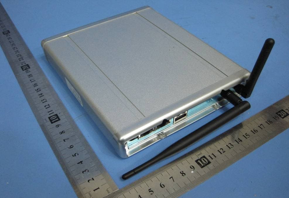
OU4-XG1000S-W
Jun 27, 2010WIFI GATEWAY
Equipment Class
DSC - Part 15 Security/Remote Control Transmitter
OU4-XCB80-FA
Feb 21, 2010FIRST ALERT BRIDGE
Equipment Class
DXX - Part 15 Low Power Communication Device Transmitter
OU4XPC280
Mar 21, 2007GARAGE DOOR CONTROL
Equipment Class
DSC - Part 15 Security/Remote Control TransmitterOU4XG1000
Jul 12, 2006XANBOO REMOTE MONITORING AND ACCESS GATEWAY
Equipment Class
DSR - Part 15 Remote Control/Security Device Transceiver
OU4-XRT750
May 10, 2005Repeater for Wireless Sensors
Equipment Class
DSR - Part 15 Remote Control/Security Device Transceiver