OU4-IG3Video Gateway
Xanboo, Inc.
Click to zoom
Application Details
- Equipment Class
- DSR - Part 15 Remote Control/Security Device Transceiver
- Date of Grant
- May 27, 2003
- Application Purpose
- Original Equipment
- Date of Application
- May 27, 2003
- Equipment Note
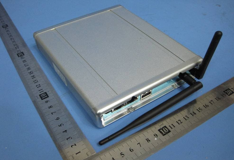
- Video Gateway
- Frequency Range
- 418.20000000 - 418.20000000
- Company
- Xanboo, Inc.
- Country
- United States
Documents & Files
Document Text
Text extracted from the exhibit documents filed with the FCC. Open a document above to read the original.
Users Manual
Xanboo iG3 Installation Guide Product Description The Xanboo iG3 Gateway connects to your high speed Internet service so you can view and control your home remotely through the Internet. Package Contents • (1) Gateway • (1) 15v Power Supply • (1) 6’ Ethernet Cable • (1) Mounting hardware kit • (1) Installation guide 1) Plug Ethernet network cable into the LAN jack on the back of the gateway. Connect the other end into your router or directly into your cable/DSL modem. Note: if you are plugging it directly into your cable/DSL modem, you may need to reset it after powering up the gateway. 2) Plug the two wired cameras into ‘CAM 1’ and ’CAM 2’ ports. 3) Plug the power adapter into the ‘Power’ port on the back of the gateway. Plug the other end into an available power outlet. 4) The ‘Service’ light on the front of the gateway will blink red for a period of 1-3 minutes. It should then go to a solid yellow. Note: If it continues to blink Red, please consult the troubleshooting section in the iG3 manual. 5) Before configuring your gateway, you must create an account on the Xanboo network. Point your browser to http://ng.xanboo.com . Click on the ‘Register New Account’ link to get to the account creation page. Fill in all of the fields and click submit to create your account. 6) You will first need to access it from a PC located on the same network. Place the CD provided into your PC and launch the XanAssist setup program. 7) Follow the installation wizard to install Xanassist. After it is finished installing it is recommended that you reboot your computer. 8) Launch XanAssist by clicking the icon that was placed on your desktop. 9) You should now see your gateway appear in the list. Select it and click the ‘Launch’ button. Note: If you do not see your gateway appear in the list, please consult the troubleshooting section at the end of this document. 10) In order to configure the gateway you must first log into it. Type ‘admin’ for the login name and ‘admin’ for the password. This is the default setting and can be changed later. Note: This is the login for the local admin which is different then your xanboo account created above. 11) Follow the setup wizard to configure your gateway and register devices 12) Set the date and time and then click next 13) Choose a name for the gateway and then click next. 14) Enter the Xanboo account created in Step #5 and then click next. Note: The login and password fields are case sensitive. 15) You will now need to ‘discover’ the devices you wish to use with the gateway (cameras, sensors, etc). Be sure that your wired cameras are plugged into the gateway before you start the discovery process. Also make sure your wireless devices are located in the desired location and are powered properly. A 9v power adapter powers the wireless cameras. When plugged in, the light on the camera will turn red. The wireless sensors are powered by two ‘AAA’ batteries (included). Slide the battery cover off and make sure the batteries are inserted properly. The light on the sensor will turn on briefly each time the sensor is opened or closed. Otherwise, check the batteries again. Click the ‘Next’ button to start discovering your devices. Note: The discovery process will automatically timeout after 10 minutes. 16) This page will automatically refresh every 15 seconds. As devices are discovered, they will appear in this list on each page refresh. 17) At this time, using a paper clip, press the discovery button on the back of the wireless cameras. The light on the camera will turn green when the gateway has discovered it properly. Note: If the light does not turn green, please consult the troubleshooting section of the camera guide. 18) If you have purchased any wireless sensors, repeat this step. 19) Go back to your PC and check that the page displayed in your browser now displays all of the devices you have discovered. Note: You can always add devices later if you have not discovered all of them at this time. 20) Click Next. You are now finished with the first time setup. Click next again to get to the home page of the configuration screens. Note: The next time you log in, you will see this page. The setup wizard only appears the first time the gateway is powered or after it has been reset. 21) You are now ready to interact with your devices. Point your browser to http://ng.xanboo.com and proceed to login with the user name and password you setup in step #5. 22) The ‘Inbox’ is the default view you will see upon logging on. This will contain a list of items that represent: • Events: Door sensor open/close • Images: Captured manually or through motion sensor events • Video Clips: Captured manually. Note: playing back the video clips requires installation of the Quicktime player. Point your browser to http://www.apple.com/quicktime USING XANBOO.COM 1) The ‘Control Panel’ allows you to control your gateway and devices. After clicking on it you will see your gateway name you selected during setup as well as the devices you discovered. Controlling Cameras 1. Click on a camera link from the ‘Control Panel’ to control the camera. 2. Click Play to turn on the web camera. Note: it may take up to 60 seconds before you may see the image on the initial loading. While it is loading you will see a ‘static’ image. This image is not coming from the cameras. 3. Click on the ‘Arm’ button to arm the cameras motion sensor 4. Click on the ‘Image’ or ‘Video’ button to capture an image or video clip. Note: It may take up to 60 seconds for the image or video to appear in your inbox. 5. You can also adjust the brightness, contrast and quality settings. A higher quality setting will result is clearer images but a larger byte size of the file. 6. To have your captured images stamped with the camera name, turn the ‘Logo’ option to enabled. 7. If you wish to rename the camera, simply click on the ‘Rename’ link. 8. Click on the ‘Control Panel’ to control other cameras or sensors. Each camera will retain its own s…
Text truncated - open the document above for the full version.
Attestation Statements
1 Scott McCutchan From: Scott McCutchan [[email protected]] Sent: Wednesday, May 14, 2003 11:00 AM To: [email protected] Subject: FCC ID: OU4-IG3 Mr. Sandoval, In order for processing of this application (FCC ID: OU4-IG3) to continue, the following issue(s) will have to be addressed: 1) Please indicate compliance with the voltage variation requirements contained in CFR 47, Part 15, Section 15.31(e). 2) More internal photos are necessary. Photographs should be taken with the shield removed from the RF section, revealing the circuitry within. Also, the photographs submitted should be supplemented with close up photos of the board. If necessary, multiple close-up photos of each side of the board may be taken, to more clearly reveal component placement and circuit board traces. 3) The operational description needs to be more specific. It should state whether the device is manually or automatically operated, and how the device complies with the operational restrictions contained in 15.231(a)(1-4). The type of modulation utilized should also be indicated. 4) Please indicate whether the accessories used during the test are unmodified, commercially available cameras. The item(s) indicated above must be submitted before processing can continue on the above referenced application. Failure to provide the requested information within 60 days of the original e-mail date may result in application dismissal and forfeiture of the filing fee. Also, please note that partial responses increase processing time and should not be submitted. Please upload your response to our electronic filing website using a correspondance number of "OU4-IG3-1". If you have any questions, feel free to contact me. Best regards, Scott McCutchan Operations Manager Compatible Electronics TCB (714) 579-1489 fax (714) 579-1850 http://www.celectronics.com Correspondence by Project Project Number: -1720351142 Correspondence Number MemoMr. McCutchan, Below are the responses to the issues you addressed in the previous e-mail: 1) Please indicate compliance with the voltage variation requirements contained in CFR 47, Part 15, Section 15.31(e). The Video Gateway, model: iG3 complies with the FCC CFR 47, Part 15, Section 15.31(e) voltage variation requirements. The radiated signal level of the fundamental does not deviate when the power supply voltage was varied. 2) More internal photos are necessary. Photographs should be taken with the shield removed from the RF section, revealing the circuitry within. Also, the photographs submitted should be supplemented with close up photos of the board. If necessary, multiple close-up photos of each side of the board may be taken, to more clearly reveal component placement and circuit board traces. The photos have been uploaded. 3) The operational description needs to be more specific. It should state whether the device is manually or automatically operated, and how the device complies with the operational restrictions contained in 15.231(a)(1-4). The type of modulation utilized should also be indicated. The operation description has been uploaded. 4) Please indicate whether the accessories used OU4-IG3-1 during the test are unmodified, commercially available cameras. The cameras are commercially available and they are a Xanboo product. See www.xanboo.com . Also the test report (C21204H1) has also been uploaded. If you have any questions or concerns, feel free to contact me anytime. Regards, Carlos Sandoval Compatible Electronics [email protected] TEL: 949-589-0700 FAX: 949-589-7700 -----Original Message----- From: Scott McCutchan [mailto:[email protected]] Sent: Wednesday, May 14, 2003 11:00 AM To: [email protected] Subject: FCC ID: OU4-IG3 Mr. Sandoval, In order for processing of this application (FCC ID: OU4-IG3) to continue, the following issue(s) will have to be addressed: 1) Please indicate compliance with the voltage variation requirements contained in CFR 47, Part 15, Section 15.31(e). 2) More internal photos are necessary. Photographs should be taken with the shield removed from the RF section, revealing the circuitry within. Also, the photographs submitted should be supplemented with close up photos of the board. If necessary, multiple close-up photos of each side of the board may be taken, to more clearly reveal component placement and circuit board traces. 3) The operational description needs to be more specific. It should state whether the device is manually or automatically operated, and how the device complies with the operational restrictions contained in 15.231(a)(1-4). The type of modulation utilized should also be indicated. 4) Please indicate whether the accessories used during the test are unmodified, commercially available cameras. The item(s) indicated above must be submitted before processing can continue on the above referenced application. Failure to provide the requested information within 60 days of the original e-mail date may result in application dismissal and forfeiture of the filing fee. Also, please note that partial responses increase processing time and should not be submitted. Please upload your response to our electronic filing website using a correspondance number of "OU4-IG3-1". If you have any questions, feel free to contact me. Best regards, Scott McCutchan Operations Manager Compatible Electronics TCB (714) 579-1489 fax (714) 579-1850 http://www.celectronics.com
Cover Letter(s)
April 25, 2003 Federal Communications Commission 7435 Oakland Mills Road Columbia, MD 21046 Subject: Request for withholding from public disclosure the schematics and associated text descriptions, block diagrams and associated text descriptions, assembly drawings and theory of operation. Gentlemen: We, Xanboo, Inc., would like to request that all schematics and associated text descriptions, block diagrams and associated text description, assembly drawings and theory of operation, submitted with the application for certification be withheld from public disclosure as per Section 0.459 of FCC Rules. This request is made under the provisions of Section 0.457 (d) of the Commission’s Rules and Section 552 (b)(4) of the Freedom of Information Act. These sections authorize as a withholding from public inspection materials which would be privileged as a matter of law if retained by the person submitting them, and materials which would not customarily be released to the public by that person. If you have any questions, please do not hesitate to contact us at 646-674-3000. Sincerely, Bill Diamond President
ID Label/Location Info
73/23/EEC, EN60950:1992 CE Standards:93/68/EFC, 89/336/EEC, BS EN 50082-1:1992 including interference that may cause undesired operation. 2) This device must accept any interference received, 1) This device may not cause harmful interference and Operation is subject to the following conditions: This device complies with Part 15 of the FCC rules. FCC ID: OU4-IG3 XANBOO 60 mm 22mm FCC ID OU4-IG3 A B Number Sheet 1 of 1 Drawn by: KEB File Name: OU4IG3.pcbDate: 3-9-2003 Rev Size Title Part 15 Label Xanboo Xanboo XLS-1000 Label OU4-IG3
Test Report
FCC-ID: OU4-IG3 Report Number: C21204H1 19121 EL TORO ROAD, LAKE FOREST, CALIFORNIA, 92676 • PHONE: (949) 589-0700 FAX: (949) 589-7700 Page 1 of 17 FCC PART 15, SUBPART C TEST REPORT for VIDEO GATEWAY Model: iG3 Prepared for XANBOO, INC. 115 WEST 30 TH STREET – 6 FLOOR NEW YORK CITY, NEW YORK 10001 Prepared by:_____________________ CARLOS SANDOVAL Approved by:____________________ BRIAN VOEGELE COMPATIBLE ELECTRONICS, INC. 19121 EL TORO ROAD LAKE FOREST (SILVERADO), CALIFORNIA 92676 (949) 589-0700 DATE: MAY 15, 2003 REPORT APPENDICES TOTAL BODY A B C D E PAGES 17 2 2 13 31 2 67 This report shall not be reproduced except in full, without the written approval of Compatible Electronics. FCC-ID: OU4-IG3 Report Number: C21204H1 19121 EL TORO ROAD, LAKE FOREST, CALIFORNIA, 92676 • PHONE: (949) 589-0700 FAX: (949) 589-7700 Page 2 of 17 TABLE OF CONTENTS Section / Title PAGE GENERAL REPORT SUMMARY 4 SUMMARY OF TEST RESULTS 4 1. PURPOSE 5 2. ADMINISTRATIVE DATA 6 2.1 Location of Testing 6 2.2 Traceability Statement 6 2.3 Cognizant Personnel 6 2.4 Date Test Sample was Received 6 2.5 Disposition of the Test Sample 6 2.6 Abbreviations and Acronyms 6 3. APPLICABLE DOCUMENTS 7 4. DESCRIPTION OF TEST CONFIGURATION 8 4.1 Description of Test Configuration - EMI 8 4.1.1 Cable Construction and Termination 9 5. LISTS OF EUT, ACCESSORIES AND TEST EQUIPMENT 10 5.1 EUT and Accessory List 10 5.2 EMI Test Equipment 11 5.3 EMI/EMC Measurement and Control Software Information 12 6. TEST SITE DESCRIPTION 13 6.1 Test Facility Description 13 6.2 EUT Mounting, Bonding and Grounding 13 7. TEST PROCEDURES 14 7.1 Conducted Emissions Test 14 7.2 Radiated Emissions (Spurious and Harmonics) Test 15 7.3 Bandwidth of the Fundamental 16 8. CONCLUSIONS 17 FCC-ID: OU4-IG3 Report Number: C21204H1 19121 EL TORO ROAD, LAKE FOREST, CALIFORNIA, 92676 • PHONE: (949) 589-0700 FAX: (949) 589-7700 Page 3 of 17 LIST OF APPENDICES APPENDIX TITLE A Modifications to the EUT B Additional Models Covered Under This Report C Diagrams, Charts and Photos • Test Setup Diagrams • Radiated Emissions Photos • Antenna and Effective Gain Factors D Data Sheets E • Laboratory Accreditations and Recognitions LIST OF FIGURES FIGURE TITLE 1 Conducted Emissions Test Setup 2 Plot Map And Layout of Test Site FCC-ID: OU4-IG3 Report Number: C21204H1 19121 EL TORO ROAD, LAKE FOREST, CALIFORNIA, 92676 • PHONE: (949) 589-0700 FAX: (949) 589-7700 Page 4 of 17 GENERAL REPORT SUMMARY This electromagnetic emission test report is generated by Compatible Electronics Inc., which is an independent testing and consulting firm. The test report is based on testing performed by Compatible Electronics personnel according to the measurement procedures described in the test specifications given below and in the "Test Procedures" section of this report. The measurement data and conclusions appearing herein relate only to the sample tested and this report may not be reproduced without the written permission of Compatible Electronics, unless done so in full. This report must not be used to claim product endorsement by NVLAP or any other agency of the U.S. Government. Device Tested: Video Gateway Model: iG3 S/N: Prototype Product Description: The iG3 is a Home Security, Control, and Monitoring System. It has provisions for three hardwired cameras and one wireless camera. The three-hardwired camera ports accept a standard camera. From the four Audio/Video sources, one is selected through the software. The audio and video signal is then over Ethernet for remote viewing. The Video Gateway also can remotely control other devices such as cameras, door locks, etc. Modifications: The EUT was not modified during the testing. Customer: Xanboo, Inc. 115 West 30 th Street – 6 Floor New York City, New York 10001 Test Date: December 2, 3, and 4, 2002 Test Specifications : EMI requirements CFR Title 47, Part 15, Subpart B and CFR Title 47, Part 15 Subpart C, Sections 15.205, 15.207, 15.209, and 15.231 Test Procedure: ANSI C63.4: 1992 Test Deviations: The test procedure was not deviated from during the testing. SUMMARY OF TEST RESULTS TEST DESCRIPTION RESULTS 1 Conducted RF Emissions, 150 kHz - 30 MHz Complies with the Class B limits of CFR Title 47, Part 15, Subpart B. 2 Radiated RF Emissions, 10 kHz - 4300 MHz Complies with the limits of CFR Title 47, Part 15, Subpart C, sections 15.205, 15.209, and 15.231. FCC-ID: OU4-IG3 Report Number: C21204H1 19121 EL TORO ROAD, LAKE FOREST, CALIFORNIA, 92676 • PHONE: (949) 589-0700 FAX: (949) 589-7700 Page 5 of 17 1. PURPOSE This document is a qualification test report based on the Electromagnetic Interference (EMI) tests performed on the Video Gateway, Model: iG3. The EMI measurements were performed according to the measurement procedure described in ANSI C63.4: 1992. The tests were performed in order to determine whether the electromagnetic emissions from the equipment under test, referred to as EUT hereafter, are within the specification limits defined by CFR Title 47, Part 15, Subpart B and CFR Title 47, Part 15, Subpart C, sections 15.205, 15.207, 15.209, and 15.231. FCC-ID: OU4-IG3 Report Number: C21204H1 19121 EL TORO ROAD, LAKE FOREST, CALIFORNIA, 92676 • PHONE: (949) 589-0700 FAX: (949) 589-7700 Page 6 of 17 2. ADMINISTRATIVE DATA 2.1 Location of Testing The EMI tests described herein were performed at the test facility of Compatible Electronics, 19121 El Toro Road, Lake Forest (Silverado), California, 92676. 2.2 Traceability Statement The calibration certificates of all test equipment used during the test are on file at the location of the test. The calibration is traceable to the National Institute of Standards and Technology (NIST) . 2.3 Cognizant Personnel Dpac Technologies Paul Shklanko Sr. Electronics Engineer Xanboo, Inc. Bill Diamond President Compatible Electronics, Inc. Carlos Sandoval Test Technician Kyle Fujimoto Test Engineer Brian Voegele Lab Manager – Lake Forest (Silverado) Division 2.4 Date Test Sample was Received The test sample was…
Text truncated - open the document above for the full version.
Contact Information
Applicant
Kent E Britain(Sr. RF Engineer)
Technical Contact
Compatible ElectronicsCarlos Sandoval
[email protected]949-589-0700
19121 El Toro Road · Lake Forest, California · United States
Test Firm
Compatible ElectronicsBrian Voegele
Technical Specifications
| # | Rule Parts | Frequency Range | Power Output |
|---|---|---|---|
| 1 | 15.231 | 418.2 MHz - 418.2 MHz | - |
Other Applications from Xanboo, Inc.
OU4-XG1000S-W
Jun 27, 2010WIFI GATEWAY
Equipment Class
DSC - Part 15 Security/Remote Control Transmitter
OU4-XCB80-FA
Feb 21, 2010FIRST ALERT BRIDGE
Equipment Class
DXX - Part 15 Low Power Communication Device Transmitter
OU4XPC260
Mar 21, 2007LAMP DIMMER
Equipment Class
DSC - Part 15 Security/Remote Control Transmitter
OU4XPC280
Mar 21, 2007GARAGE DOOR CONTROL
Equipment Class
DSC - Part 15 Security/Remote Control TransmitterOU4XG1000
Jul 12, 2006XANBOO REMOTE MONITORING AND ACCESS GATEWAY
Equipment Class
DSR - Part 15 Remote Control/Security Device Transceiver