OU4-XBX200XBX200 Superxan Transmitter
Xanboo, Inc.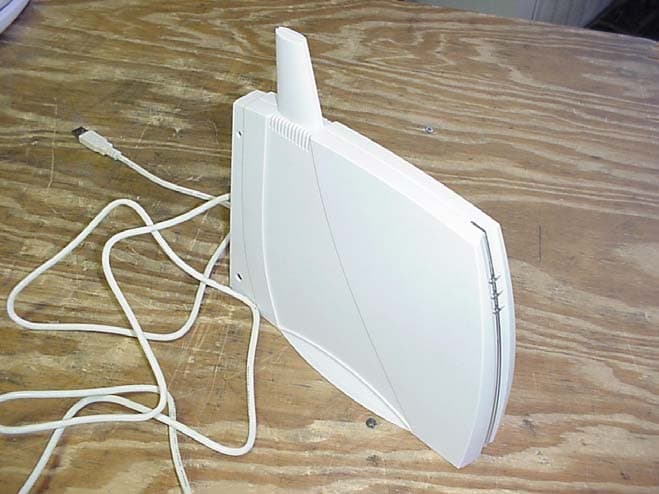
Click to zoom
Application Details
- Equipment Class
- DSC - Part 15 Security/Remote Control Transmitter
- Date of Grant
- Feb 15, 2004
- Application Purpose
- Original Equipment
- Date of Application
- Feb 15, 2004
- Equipment Note
- XBX200 Superxan Transmitter
- Frequency Range
- 418.00000000 - 418.00000000
- Company
- Xanboo, Inc.
- Country
- United States
Documents & Files
Document Text
Text extracted from the exhibit documents filed with the FCC. Open a document above to read the original.
Users Manual
Exhibit J: Users Manual Xanboo XBX200 Superxan Transmitter Manual – First Draft Product Description The Motorola Home Monitoring & Control USB Controller allows local control of Xanboo enabled devices including cameras, sensors and power controllers. Devices can be armed to store events, image and video clips right on your hard drive for archiving and viewing. Additionally, it allows you to upgrade to Xanboo’s remote viewing and control service across the internet. Package Contents • (1) Motorola USB Controller • (1) 15v Power Supply • (1) 6’ Ethernet Cable • (1) Installation guide and CD Installing the software 1. Insert the Installation CD into the CD drive of your computer 2. Select the installation folder you wish to install the application to and click Next 3. After the files have been copied to your computer you will need to restart windows. 4. You are now ready to connect your Motorola USB Controller and configure your devices Connecting the Motorola USB Controller to your PC 1. Plug the USB plug into an available USB port on your PC. 2. Plug the power adapter into a power outlet and into the power port on the back of the Motorola USB Controller . The LED on the front of the Motorola USB Controller will now turn blue. 3. Launch the application by going to the start menu Discovering Devices In order for the Motorola USB Controller to use and control devices like cameras and sensors, each device must be registered with the it. In a sense the it establishes a closed wireless “network” between the Motorola USB Controller and all discovered devices. The Motorola USB Controller will only control and use the devices it discovers. New devices can be discovered at any time. 1. Start the application from the start menu 2. Click on the Setup Button and 3. If you have wired cameras, plug them into the camera ports on the back of the Motorola USB Controller . These will be automatically discovered. 4. Click the Add Device button item to begin discovery 5. For wireless sensors and cameras, simply push the discovery button on the device while the Motorola USB Controller is in discover mode. Please consult the devices manual for more detailed instructions. 6. As each device is detected by the Motorola USB Controller , it will be listed in the window. NOTE: This page will refresh every 10 seconds to show newly discovered devices. You may have to wait for a refresh to see the device listed 7. Click on the Stop Discovery button when you are finished discovering all of your devices. Your Motorola USB Controller and devices are now ready to be used. Configuring Devices 1. Start the application from the start menu 2. Select the Control Panel button 3. Select the Settings icon next to the device you wish to configure 4. Select the settings and click the Set button when complete Controlling Cameras 5. Start the application from the start menu 6. Select the Control Panel button 7. Select the camera that you wish to view from the camera list 8. To capture an image select the image capture button 9. To capture a video select the video capture button Arming /Disarming the System 1. Start the application from the start menu 2. Click on the Control Panel button 3. To arm the system and all devices, select the arm button 4. To disarm the system and all devices, select the disarm button Viewing the archive The Motorola USB Controller stores all informational events, image and video clips locally in the default data folder. To access the information do the following: 1. Start the application from the start menu 2. Click on the Archives button 3. To view details about the item, click on it 4. To remove the item from the archive select it and click on Delete Enabling Remote Service Using the Remote Service feature, you will be able to get access to the Motorola USB Controller remotely across the internet.Note: you must subscribe to the remote service (monthly fee) and have a broadband connection 1. Start the application from the start menu 2. Click on the Remote Service button 3. Fill out the form to register a new account and click the Submit button 4. Upon completion of the registration process, you will now be able to access you system via the www.xanboo.com website. Note: all items will now be stored on the web server and not locally on your hard drive. All existing items will not be moved. Motorola USB Controller Ports • CAM1-3: Connect wired cameras to these ports • A/V Out: Use a TV enabling cable to view the currently viewed camera on your TV or VCR • Power: Connect the 12V power adapter Troubleshooting SYMPTOM REMEDY Wireless Video problems 1. Check the VIDEO status indicator to observe the quality of the signal. 2. Try moving the camera or Motorola USB Controller to different positions (typical range will be from 60- 100 feet) 3. Move the camera or Motorola USB Controller away from potential interfering devices including cordless phones, microwaves and wireless networks. 4. Consult the wireless camera user guide for more troubleshooting tips Wireless devices are not being discovered 1. Ensure the Motorola USB Controller has an active internet connection 2. Check to see that the WIRELESS status indicator is not solid red or unlit. 3. Try moving the devices closer in proximity to the Motorola USB Controller . Typical discovery range will be 60-100 feet. 4. Re-power or reset the camera or sensor and try again. The Motorola USB Controller does not seem to be responding to 1. Ensure that the Motorola USB Controller has an active internet connection. The LAN and SERVICE indicator should be green. commands I issue on the website 2. Ensure that the Motorola USB Controller is registered with the same account that you are logged in as 3. Verify that you can log into the Motorola USB Controller Admin pages locally 4. Re-power the Motorola USB Controller or press the RESET button My camera images are black 1. Ensure the camera is plugged into the proper port 2. Check to make sure the brightness setting is set to an a…
Text truncated - open the document above for the full version.
Block Diagram
Exhibit F: Block Diagram Xanboo XBX200 Superxan Transmitter
Cover Letter(s)
Exhibit K: Letter of Confidentiality Xanboo XBX200 Superxan Transmitter American Telecommunications Certification Body, Inc. 6731 Whittier Ave. McLean, VA 22101 February 6, 2004 RE: Certification Application FRN: 0007774151 FCC ID: OU4-XBX200 Please be advised the following information is to be held confidential on behalf of Company. • Schematics • Theory of operation Thank you, M Ghalebi Senior Vice president (Engineering)
Cover Letter(s)
Exhibit I: Letter of Authorization Xanboo XBX200 Superxan Transmitter
External Photos
Exhibit E2: EUT External Photos Xanboo XBX200 Superxan Transmitter Xanboo XBX200 Superxan Transmitter EUT External View Xanboo XBX200 Superxan Transmitter
ID Label/Location Info
Exhibit C: Label Location Xanboo XBX200 SuperXan Transmitter Xanboo SuperXan Gateway This device complies with part 15 of the FCC rules. Made in China Serial No Xanboo Inc, New York USA FCC ID Number: OU4-XBX200 Tested to Comply With FCC Standards FOR HOME OR OFFICE USE Operation is subject to the following two conditions: 1) This device may not cause harmful interference, and 2) This device must accept any interference received, including interference that may cause undesired operation.
Internal Photos
Exhibit E1: EUT Internal Photos Xanboo XBX200 Superxan Transmitter Xanboo XBX200 Superxan Transmitter Xanboo XBX200 Superxan Transmitter Xanboo XBX200 Superxan Transmitter
Test Report
Professional Testing (EMI), Inc. 1 Exhibit B: Test Report Xanboo XBX200 Superxan Transmitter Professional Testing (EMI) Inc. Report No. 04046-10 Page 2 of 19 Project Number: 04046-10 Prepared for: Xanboo 1626 Vineyard Grand Praire , TX 75052 By Professional Testing (EMI), Inc. 1601 FM 1460, Suite B Round Rock, Texas 78664 December 2003 CERTIFICATION Electromagnetic Interference Test Report Xanboo Superxan, Model XPX200 (Intentional Radiator Portion) Professional Testing (EMI) Inc. Report No. 04046-10 Page 3 of 19 Table of Contents Title Page .........................................................................................................................................1 Table of Contents .............................................................................................................................2 Certificate of Compliance ................................................................................................................3 1.0 EUT Description ......................................................................................................................5 1.1 EUT Operation.........................................................................................................................5 2.0 Electromagnetic Emissions Testing.........................................................................................6 2.1 Conducted Emissions Measurements ..................................................................................6 2.1.1 Test Procedure ................................................................................................................6 2.1.2 Test Criteria ....................................................................................................................6 2.1.3 Test Results .....................................................................................................................6 2.2 Radiated Emissions Measurements .....................................................................................7 2.2.1 Test Procedure ................................................................................................................7 2.2.2 Test Criteria ....................................................................................................................7 2.2.3 Test Results .....................................................................................................................8 3.0 Occupied Bandwidth Measurements .......................................................................................8 3.2 Test Criteria .........................................................................................................................8 3.3 Test Results ..........................................................................................................................8 4.0 Antenna Requirement ..............................................................................................................9 4.1 Evaluation Procedure ...........................................................................................................9 4.3 Evaluation Results ...............................................................................................................9 5.0 Modifications to Equipment ..................................................................................................10 6.0 List of Test Equipment...........................................................................................................10 Figures FIGURE 1: Conducted Emissions Mains Terminal Measurements ............................................. 11 FIGURE 2: Radiated Emissions Test Setup ................................................................................. 12 Appendices Appendix A: Emissions Data Sheet................................................................................................ 13 Appendix B: Occupied Bandwidth Data Sheets.............................................................................. 18 THIS REPORT SHALL NOT BE REPRODUCED EXCEPT IN FULL, WITHOUT THE WRITTEN APPROVAL OF PROFESSIONAL TESTING (EMI), INC. Professional Testing (EMI) Inc. Report No. 04046-10 Page 4 of 19 Applicant: Xanboo Applicant’s Address: 1626 Vineyard Grand Praire, TX 75052 Serial Number: N/A FCC ID: OU4-XBX200 Project Number: 04046-10 Test Dates: July 7, 2003 I, Jeffrey A. Lenk, for Professional Testing (EMI), Inc., being familiar with the FCC rules and test procedures have reviewed the test setup, measured data and this report. I believe them to be true and accurate. The Xanboo, Superxan, Model XPX200 was tested to and found to be in compliance with FCC Part 15 Subpart C for an Intentional Radiator. The highest emissions generated by the above equipment are listed below: Frequency (MHz) Level (dBμV/m) Limit (dBμV/m) Margin (dB) Fundamental 418 74.2 80.3 -6.8 Spurious 836 41.5 60.3 -18.8 Conducted 0.15 54.6 66 -11.4 Occupied Bandwidth 125.2 ______________________________ Jeffrey A. Lenk President This report has been reviewed and accepted by Xanboo. The undersigned is responsible for ensuring that Xanboo, Superxan, Model XPX200 will continue to comply with the FCC rules. ______________________________ Certificate of Compliance Professional Testing (EMI) Inc. Report No. 04046-10 Page 5 of 19 1.0 EUT Description The Equipment under Test (EUT) is the Xanboo, Superxan, Model XPX200. The Superxan is a wireless transmitter used for security systems, powered by the USB port of the host computer. It accepts additional TV cameras powered by a “Wall Wart” transformer. It has three ports for wired cameras. Top two ports are for development use and have no field use. The EUT operates at 418 MHz and is designed for compliance with 47 CFR 15.231 of the FCC rules. Specific test requirements for this device include the following: 47 CFR 15.209 & 15.231 Fundamental Transmit Power 47 CFR 15.231 & 15.205 Spurious Radiated Power 47 CFR 15.231 Occupied Bandwidth 47 CFR…
Text truncated - open the document above for the full version.
Test Setup Photos
Exhibit D: Test Setup Photos Xanboo XBX200 Superxan Transmitter Xanboo XBX200 Superxan Transmitter Conducted Emissions Xanboo XBX200 Superxan Transmitter Radiated Emissions
Contact Information
Applicant
Kent E Britain(Sr. RF Engineer)
Technical Contact
Professional Testing (EMI) Inc.Mike Royer
[email protected](512) 244 3371
1601 FM 1460, Suite B · Round Rock, Texas · United States
Test Firm
Professional Testing (EMI), Inc.Michael Royer
Technical Specifications
| # | Rule Parts | Frequency Range | Power Output |
|---|---|---|---|
| 1 | 15.231 | 418 MHz - 418 MHz | - |
Other Applications from Xanboo, Inc.
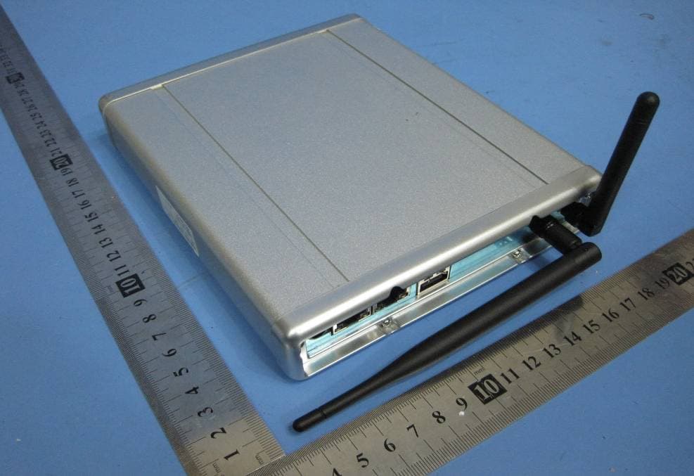
OU4-XG1000S-W
Jun 27, 2010WIFI GATEWAY
Equipment Class
DSC - Part 15 Security/Remote Control Transmitter
OU4-XCB80-FA
Feb 21, 2010FIRST ALERT BRIDGE
Equipment Class
DXX - Part 15 Low Power Communication Device Transmitter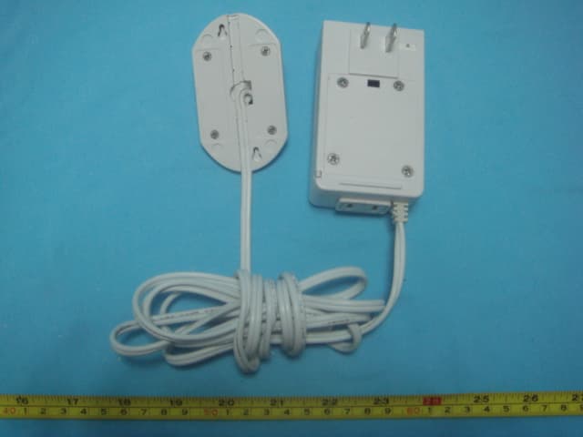
OU4XPC260
Mar 21, 2007LAMP DIMMER
Equipment Class
DSC - Part 15 Security/Remote Control Transmitter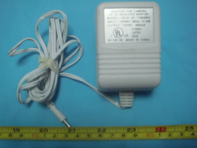
OU4XPC280
Mar 21, 2007GARAGE DOOR CONTROL
Equipment Class
DSC - Part 15 Security/Remote Control TransmitterOU4XG1000
Jul 12, 2006XANBOO REMOTE MONITORING AND ACCESS GATEWAY
Equipment Class
DSR - Part 15 Remote Control/Security Device Transceiver