OU4-XRT750Repeater for Wireless Sensors
Xanboo, Inc.
Click to zoom
Application Details
- Equipment Class
- DSR - Part 15 Remote Control/Security Device Transceiver
- Date of Grant
- May 10, 2005
- Application Purpose
- Original Equipment
- Date of Application
- May 10, 2005
- Equipment Note
- Repeater for Wireless Sensors
- Frequency Range
- 418.00000000 - 418.00000000
- Company
- Xanboo, Inc.
- Country
- United States
Documents & Files
Document Text
Text extracted from the exhibit documents filed with the FCC. Open a document above to read the original.
Users Manual
Exhibit J User Manual Xanboo/Core Technologies XRT750 REPEATER XRT750 USER’S GUIDE APPROVALS /// FCC ID NUMBER: OU4-XRT750 ST ANDARDS 93/68/EEC, 89/336/EEC, BS EN 50082-1:1992, 73/23/EEC, EN60950:1992 CE INSTRUCTIONS TO THE USER: The user is cautioned that changes and modifications made to the equipment without the approval of manufacturer could void the user's authority to operate this equipment. This equipment has been tested and found to comply with the limits for a class B digital device, pursuant to part 15 of the FCC Rules. These limits are designed to provide reasonable protection against harmful interference in a residential installation. This equipment generates, uses and can radiate radio frequency energy and if not installed and used in accordance with the instructions, may cause harmful interference to radio communications. However, there is no guarantee that interferences will not occur in a particular installation. If this equipment does cause harmful interference to radio or television reception, which can be determined by turning the equipment off and on, the user is encouraged to try to correct the interference by one or more of the following measures: • Reorient or relocate the receiving antenna. • Increase the separation between the equipment and receiver. • Connect the equipment into an outlet on a circuit different from that to which the receiver is connected. • Consult the dealer or an experienced radio/TV technician for help. CE directive 93/68/EEC, LV directive 73/23/EEC. Operation is subject to the following two conditions: (1) this device may not cause interference, and (2) this device must accept any interference, including interference that may cause undesired operation of the device. HELPFUL HINTS /// n The Xanboo ™ Repeater is suitable for indoor use only. FAQ’S /// HOW FAR AWAY CAN THE REPEATER BE PLACED FROM THE CONTROLLER? Typically 60 feet. CAN I PLACE THE REPEATER IN A DIFFERENT ROOM FROM THE CONTROLLER? Yes, the Repeater uses radio frequencies to communicate with the Controller. These frequencies can travel through objects such as walls, ceilings, and floors. HOW MANY SENSORS CAN I USE WITH MY CONTROLLER? The Controller can support up to 20 sensors. TECHNICAL SPECS /// n Attaches to vertical flat surfaces (antenna must point up) n Test/Discover button Typical Range Outdoors: 250 feet Typical Range Indoors: 60 feet Frequency Range: 418 MHz PRODUCT DESCRIPTION /// The Xanboo ™ Repeater “repeats” signals coming from any wireless Xanboo ™ device and “re-transmits” that signal, effectively doubling the range of any of your Xanboo ™ devices. PACKAGE CONTENTS /// n (1) Repeater n (1) 9V Power Adapter n (1) Wall Mounting Kit INSTALLATION /// The Xanboo ™ Repeater should be mounted indoors, at a height of 6-8 feet. It should be placed to facilitate other devices’ communication with the Controller. If one of your Xanboo ™ devices is having difficulty communicating with the Controller, mount the Repeater in between the two. If communication is restored, that is a good place for the Repeater. NOTE: You can only have one Repeater in between the device and the Controller. Though you can have more than one Repeater per system, repeaters will not communicate with each other, so you need to make sure that a device can make contact with the Controller using only one Repeater. Below is an example of a multi-repeater installation. 1. Peel the paper strip from the double-sided tape located on the back of the Repeater. You can also mount the Repeater more securely using the screws in the wall mounting kit. Affix the screws leaving 1/16” space between the screw head and the object. 2. Mount the Repeater onto the screws and slide down to lock into place. 2I REPEATER WALL MOUNTING KIT 9V POWER ADAPTER SENSOR THERE CAN ONLY BE ONE REPEATER IN BETWEEN THE DEVICE AND THE CONTROLLER REPEATER 1SENSORREPEATER 2CONTROLLER/PC TROUBLE SHOOTING /// PROBLEM Controller does not recognize the Device during discovery Events are not triggered Device does not respond when used SOLUTION 1. Position the Device in closer proximity to the Controller and try again. 2. Ensure there are no other wireless devices interfering with the Motorola Device, which transmits on the 418MHz frequency. 3. If you determine that the Device is simply too far away from the Controller, then you have the option of purchasing a Motorola Repeater to effectively double the range of the Device. 1. Has the Device been registered properly with your Gateway? 2. Ensure that you have the proper settings configured for the new Device. 1. Ensure the new Device has been registered properly with the Controller by viewing the status of the Device on your PC Software. 2. Place the Device in another location closer to the Controller. 3. Press the ‘Test’ button on the Device to confirm that it is working. 4. If you determine that the Device is too far from the Controller, you can add a Repeater to the system to effectively double the range of the Device.
Cover Letter(s)
1601 FM 1460, Suite B Round Rock, TX 78664 e-mail: [email protected] 512/244-3371 Fax: (512)244-1846 May 10, 2005 FCC ID: OU4-XRT750 IC Number: 4576A-XRT750 In response to your comments regarding the application for certification of the devices referenced above please find our response below: 1. Information regarding the tethering process. The repeater learns which sensors are in the system by monitoring the sensor registration process or by monitoring successful friendly exchanges between base and sensor. If the repeater is introduced to a system where a sensor is already out of range of the base, then that sensor will need to be moved into range for the repeater to accept it. The users manual has omitted this information in error. 2. How are acknowledge packet handled? The repeater forwards the acknowledge packet back to the remote sensor. The acknowledge packet is delayed by the watchdog timer circuit so that the 10 second silent period is observed. 3. How many remote sensors can a repeater service? Four. 4. How does the repeater handle closely spaced multiple messages? The watchdog timer forces a 10 second space between forwarded message transmissions. 5. What is the decision process for transmitting? If a sensor which is already considered part of the system (see 1 above) is not acknowledged by the base, then the repeater will forward the message by making its own message to the base. One of the header bits is flipped to tag the message as a repeated message.
Cover Letter(s)
BE THERE /// EVEN WHEN YOU’RE NOT 115 W 30TH ST. NEW YORK, NY 10001 P: 212.714.2295 /// F: 212.714.2491 /// www.xanboo.com To: Professional Testing Inc: Attn: Mike Royer Date: May 9, 2005 Subject: Technical Questions regarding XRT-750 1. How does the device know which remote devices it is associated with? The repeater has a considerable amount of processing power and memory. The repeater monitors the "Discovery Process" and there is a propriety learning program that allows it to learn the other security sensors in the Xanboo system. The repeater transmits a 19.5 millisecond Discovery packet when first installed. It does not transmit a System Integrity packet. In normal operation the repeater could run for months without transmitting a single packet. 2. How does the device know which base station it is associated with? Each Xanboo device is registered at close range with the base station via the discovery process. i.e. the discovery button is pressed only when the Base station is in discovery mode. The device ID appears on a screen and user accepts it. The repeater is not a sensor, it does not exchange system integrity packets with the base station. 3. What specifically is the repeater looking for to make a decision to retransmit? The repeater monitors the System Integrity or alarm packet from the Sensor. When it hears a sensor transmit, but does not hear a base station AcK signal, it repeats the sensor signal, which has been stored in memory. During the wait for the AcK signal it checks a table in it's internal memory to see if the device is a house hold registered device. Only house hold registered sensors that were not received by the base station are retransmitted. Thus the XRT-750 is functioning as a Diversity Receiver. Please let me know if I can help you with any other questions. Kent Britain Sr. RF Engineer Xanboo Inc. 972.660.2810 Lab 972.606.1909 Fax 972.849.0235 Cell [email protected]
Cover Letter(s)
1601 FM 1460, Suite B Round Rock, TX 78664 e-mail: [email protected] 512/244-3371 Fax: (512)244-1846 May 6, 2005 FCC ID: OU4-XRT750 IC Number: 4576A-XRT750 In response to your comments regarding the application for certification of the devices referenced above please find our response below: 1) Unless the device is smaller than 8x10 cm, the FCC label should still include the 2 part FCC statement: Operation is subject to the following two conditions: 1) This device may not cause harmful interference, and 2) This device must accept any interference received, including interference that may cause undesired operation. Please see external photos exhibit E2 rev2 uploaded 4/29/05. The device is less than 8x10 cm. 2) The operational description provided does not appear to be correct for this device. Please review. The correct operational description will be uploaded as Exhibit H rev2. 3) Based upon this being a repeater, a detailed description on how this device operates and insures compliance with 15.231 timing requirements and power levels should be provided. Note that to be allowed as a repeater under Part 15 the device may only transmit after receiving, demodulating, and recognizing the incoming signal prior to retransmission. The theory should explain how the device meets these requirements. Please see the revised operational description. The description explains the criteria for processing packets. 4) Two sets of schematics (within one file) appear to have been provided. Please explain or correct as necessary. Schematics exhibit has been updated and uploaded. 5) Given the nature of the device, testing should have been performed in each of 3 axis in effort to obtain worse case results. Was this performed? Testing was performed with the device in 3 orthogonal axis. The EUT’s antenna position was also manipulated to be 90 and 180 degrees relative to the case. 6) The device has an average correction factor of 13.7 dB. Please explain how this is ensured for all transactions being sent Please see the updated operational description. The correction factor has been updated to 12.6 dB. The data tables in the test report have also been updated 7) What ensures that no matter how many device transmit or need repeating, that the 10 second and 30 x TX period are maintained under all circumstances? What are worse case TX duty cycles and transmissions expected? Please see the updated operational description. The revised operational description addresses the timing issues.
Cover Letter(s)
American Telecommunications Certification Body Inc. 6731 Whittier Ave, McLean, VA 22101 April 29, 2005 RE: Xanboo/Core Technologies FCC ID: OU4-XRT750 After a review of the submitted information, I have a few comments on the above referenced Application. 1) Unless the device is smaller than 8x10 cm, the FCC label should still include the 2 part FCC statement: Operation is subject to the following two conditions: 1) This device may not cause harmful interference, and 2) This device must accept any interference received, including interference that may cause undesired operation. 2) The operational description provided does not appear to be correct for this device. Please review. 3) Based upon this being a repeater, a detailed description on how this device operates and insures compliance with 15.231 timing requirements and power levels should be provided. Note that to be allowed as a repeater under Part 15 the device may only transmit after receiving, demodulating, and recognizing the incoming signal prior to retransmission. The theory should explain how the device meets these requirements. 4) Two sets of schematics (within one file) appear to have been provided. Please explain or correct as necessary. 5) Given the nature of the device, testing should have been performed in each of 3 axis in effort to obtain worse case results. Was this performed? 6) The device has an average correction factor of 13.7 dB. Please explain how this is ensured for all transactions being sent 7) What ensures that no matter how many device transmit or need repeating, that the 10 second and 30 x TX period are maintained under all circumstances? What are worse case TX duty cycles and transmissions expected? Timothy R. Johnson Examining Engineer mailto: [email protected] The items indicated above must be submitted before processing can continue on the above referenced application. Failure to provide the requested information may result in application termination. Correspondence should be considered part of the permanent submission and may be viewed from the Internet after a Grant of Equipment Authorization is issued. Please do not respond to this correspondence using the email reply button. In order for your response to be processed expeditiously, you must submit your documents through the AmericanTCB.com website. Also, please note that partial responses increase processing time and should not be submitted. Any questions about the content of this correspondence should be directed to the sender.
Cover Letter(s)
American Telecommunications Certification Body Inc. 6731 Whittier Ave, McLean, VA 22101 May 6, 2005 RE: Xanboo/Core Technologies FCC ID: OU4-XRT750 After a review of the submitted information, I have a few comments on the above referenced Application. 1) Please provide information regarding the tethering and registration process mentioned in the new updated operational description. The device does not appear to be programmable from the users manual provided so it is uncertain how this device knows exactly what packets it can retransmit (and also reject) and what controller it is associated with. Therefore, how does the repeater know what device(s) it is associated with and which controller it is associated with? 2) If the repeater is forwarding packets onto the controller, Please explain how acknowledge packets make there way back to the sensor original sensor if the repeater is only forwarding messages in one direction only. It is assumed that if transmissions can not reach in one direction, then they would also not be able to return back as well. 3) It is also still unclear if the device is capable of forwarding information from more than one sensor, or if a repeater is only tied to one specific sensor per repeater. 4) If the repeater received 2 messages in < 1 second, does it retransmit both messages or one message? Does it transmit them as a group or space them apart. Please explain? 5) What does the device decode to ensure something is part of its system? If another system was nearby operating on the same frequency, how does this device reject it? What specifically is it looking for before it acknowledges something is valid for retransmit? Please explain. Timothy R. Johnson Examining Engineer mailto: [email protected] The items indicated above must be submitted before processing can continue on the above referenced application. Failure to provide the requested information may result in application termination. Correspondence should be considered part of the permanent submission and may be viewed from the Internet after a Grant of Equipment Authorization is issued. Please do not respond to this correspondence using the email reply button. In order for your response to be processed expeditiously, you must submit your documents through the AmericanTCB.com website. Also, please note that partial responses increase processing time and should not be submitted. Any questions about the content of this correspondence should be directed to the sender.
Cover Letter(s)
American Telecommunications Certification Body Inc. 6731 Whittier Ave, McLean, VA 22101 May 11, 2005 RE: Xanboo/Core Technologies FCC ID: OU4-XRT750 After a review of the submitted information, I have a few comments on the above referenced Application. 1) Please reverify the correction factor applied to the latest test report. The response on 5/4/05 does not appear to match the report. Timothy R. Johnson Examining Engineer mailto: [email protected] The items indicated above must be submitted before processing can continue on the above referenced application. Failure to provide the requested information may result in application termination. Correspondence should be considered part of the permanent submission and may be viewed from the Internet after a Grant of Equipment Authorization is issued. Please do not respond to this correspondence using the email reply button. In order for your response to be processed expeditiously, you must submit your documents through the AmericanTCB.com website. Also, please note that partial responses increase processing time and should not be submitted. Any questions about the content of this correspondence should be directed to the sender.
Cover Letter(s)
Exhibit I Letter of Authorization Xanboo/Core Technologies XRT750 Core Technology An Industry Leader in Home Security Wireless Applications Letter of Authorization and Anti-Drug Date: November 19, 2004 Federal Communications Commission 7435 Oakland Mills Road Columbia, Maryland 21046 Dear Sir/Madam: This is a letter of authorization to accept Professional Testing (EMI), Inc. as an agent for (Core Technology, 115 W. 30 th st, New York, NY 10001), for a period of one year, to sign applications before the Commission on our behalf, to make representations to you on our behalf, and to receive and exchange data between our company and the Commission with respect to the following Core Technology products: Product: Xanboo OU4-XRT750 Please also accept this letter as an attestation that neither Core Technology nor any of its officers, directors, or persons holding more that 5% or more of the outstanding stock or shares, voting or non-voting, have been denied federal benefits under section 5301 of the Anti-Drug-Abuse act of 1988,21 U.S.C. 853(a). In addition, Core Technology will notify the Federal Communications Commission if, at any time, the situation changes causing Core Technology to be denied federal benefits. If you have any further questions or need additional information, please feel free to give me a call at phone. Sincerely, Kent Britain Sr. RF Engineer Core Technology 972-849-0235
Cover Letter(s)
Exhibit K Letter of Confidentiality Xanboo/Core Technologies XRT750 January 6, 2005 FEDERAL COMMUNICATIONS COMMISSION 7435 Oakland Mills Road Columbia, MD 21046 U.S.A. Subject: Request for withholding from public disclosure the schematic diagram and system block diagram pursuant to an application for certification. Applicant: Xanboo Inc. 115 West 30 th Street New York, New York 10001 Product: XRT750 FCC ID: OU4-XRT750 Dear Sir/Madam, We, Xanboo/Core Technologies, request that the schematic diagram and system block diagram submitted with application for certification for FCC ID: OU4-XRT750 be withheld from public disclosure as per Section 0.459 of FCC Rules. This request is made under the provisions of Section 0.457(d) of the Commission's Rules, and Section 552(b)(4) of the Freedom of Information Act. These sections authorize as a withholding from public inspection, material which would be privileged as a matter of law if retained by the person submitting them, and material which would not customarily be released to the public by that person. The detailed confidential materials are listed as follows: Exhibit F Block Diagram.pdf Exhibit G Schematics.pdf If you have any queries, please do not hesitate to contact us by Phone or EMail. Yours truly, Kent Britain Sr. RF Engineer [email protected] 972.660.2810
External Photos
Exhibit E2 External Photos Xanboo/Core Technologies XRT750 XRT750 Back XRT750 Front Size
ID Label/Location Info
Exhibit C Label Location Xanboo/Core Technologies XRT750 XANBOO Repeater MODEL XRT750 FCC ID: OU4-XRT750 IC:4576A-XRT750 Xanboo Inc. New York USA Made in China
Internal Photos
Exhibit E1 Internal Photos Xanboo/Core Technologies XRT750 PCB Back PCB Front
Operational Description
Exhibit H Description of Operation Xanboo/Core Technologies XRT750 Product Description Using store and forward the repeater is used to extend the range of certain sensors. To accomplish this, each packet received is demodulated, decoded, and processed to determine if action is required. The repeater sends a “keep alive” packet every 15 minutes for system integrity purposes. The maximum system packet length is from the Home and Away module, which has a length of 23.3 mS. The minimum period between transmissions is 10 seconds. Apart from the above “keep alive” function, the following conditions are required for the repeater to transmit. 1. The repeater only repeats the signal of the device that it has been tethered to, not any device or any Xanboo system device. 2. The repeater only repeats if the main controller fails to acknowledge the tethered device’s original transmission. 3. The repeater will not repeat Xanboo packets intended for controllers other than the controller that it is registered to. 4. Repeaters will not function in cascade style. Two or more repeaters cannot be used in series to extend the system range. 5. A ten second watchdog timer prevents transmissions less than 10 seconds apart.
Test Report
Exhibit B Test Report Xanboo/Core Technologies Repeater XRT750 Professional Testing (EMI), Inc. Project 05230-10 Page 1 of 17 Project Number: 05230-10 Prepared for: Xanboo/Core Technologies 115 West 30th Street New York, NY 10001 By Professional Testing (EMI), Inc. 1601 FM 1460, Suite B Round Rock, Texas 78664 April 2005 CERTIFICATION Electromagnetic Interference Test Report Xanboo/Core Technologies Repeater XRT750 Professional Testing (EMI), Inc. Project 05230-10 Page 2 of 17 Table of Contents Title Page .........................................................................................................................................1 Table of Contents .............................................................................................................................2 Certificate of Compliance ................................................................................................................3 1.0 EUT Description ..................................................................................................................4 1.1 Applicable Documents.....................................................................................................4 1.2 EUT Operation.................................................................................................................4 2.0 Electromagnetic Emissions Testing.....................................................................................5 2.1 Conducted Emissions Measurements ..............................................................................5 2.1.1 Test Procedure .........................................................................................................5 2.1.2 Test Criteria .............................................................................................................5 2.1.3 Test Results ..............................................................................................................5 2.2 Radiated Emissions Measurements .................................................................................6 2.2.1 Test Procedure .........................................................................................................6 2.2.2 Test Criteria .............................................................................................................6 2.2.3 Test Results ..............................................................................................................7 3.0 Occupied Bandwidth Measurements ...................................................................................7 3.1 Test Procedure .................................................................................................................7 3.2 Test Criteria .....................................................................................................................7 3.3 Test Results ......................................................................................................................7 4.0 Antenna Requirement ..........................................................................................................8 4.1 Evaluation Procedure .......................................................................................................8 4.2 Evaluation Criteria ...........................................................................................................8 4.3 Evaluation Results ...........................................................................................................8 5.0 Modifications to Equipment ................................................................................................8 6.0 List of Test Equipment.........................................................................................................8 FIGURES Figure 1 Conducted Emissions Test Setup ....................................................................................10 Figure 2 Radiated Emissions Test Setup .......................................................................................11 APPENDICES Appendix A Emissions Data ..........................................................................................................12 THIS REPORT SHALL NOT BE REPRODUCED EXCEPT IN FULL, WITHOUT THE WRITTEN APPROVAL OF PROFESSIONAL TESTING (EMI), INC. Professional Testing (EMI), Inc. Project 05230-10 Page 3 of 17 Applicant: Xanboo/Core Technologies Applicant’s Address: 115 West 30th Street New York, NY 10001 FCC ID: OU4-XRT750 IC Number: 4576A-XRT750 Project Number: 05230-10 Test Dates: October 20-21, 2004 April 27, 2005 I, Michael A. Royer, for Professional Testing (EMI), Inc., being familiar with the FCC and IC rules and test procedures have reviewed the test setup, measured data and this report. I believe them to be true and accurate. The Xanboo/Core Technologies, Repeater XRT750 was tested to and found to be in compliance with FCC Part 15 Subpart C and RSS 210 6.1.1 for an Intentional Radiator. The highest emissions generated by the above equipment are listed below: Frequency (MHz) Level (dBμV/m) Limit (dBμV/m) Margin (dB) Fundamental 418 (peak) 76.4 92.3 -15.9 418 (avg) 63.8 72.3 -8.5 Spurious 1672 47.9 54 -8.6 Conducted 0.325 47.8 59.6 -11.8 Occupied Bandwidth 192 (kHz) Michael A. Royer, BSEE, NCE EMC Department Manager This report has been reviewed and accepted by Xanboo/Core Technologies. The undersigned is responsible for ensuring that Xanboo/Core Technologies, Repeater XRT750 will continue to comply with the FCC and IC rules. Certificate Of Compliance Professional Testing (EMI), Inc. Project 05230-10 Page 4 of 17 1.0 EUT Description Using store and forward the repeater is used to extend the range of certain sensors. To accomplish this, each packet received is demodulated, decoded, and processed to determine if action is required. The repeater sends a “keep alive” packet every 15 minutes for system integrity purposes. The maximum system packet length is from the Home and Away module, which has a…
Text truncated - open the document above for the full version.
Test Setup Photos
Exhibit D Test Setup Photos Xanboo/Core Technologies XRT750 Conducted Emissions - Front Conducted Emissions – Side Radiated Emissions – Front Radiated Emissions - Side
Contact Information
Applicant
Kent E Britain(Sr. RF Engineer)
Technical Contact
Professional Testing (EMI Inc.Jason Anderson
[email protected]512-244-3371
1601 FM 1460 Suite B · Round Rock, Texas · United States
Non-Technical Contact
Professional Testing (EMI Inc.Mark Ellis
[email protected]512-244-3371
Test Firm
Professional Testing (EMI), Inc.Jeff Link
Technical Specifications
| # | Rule Parts | Frequency Range | Power Output |
|---|---|---|---|
| 1 | 15.231(e) | 418 MHz - 418 MHz | - |
Other Applications from Xanboo, Inc.
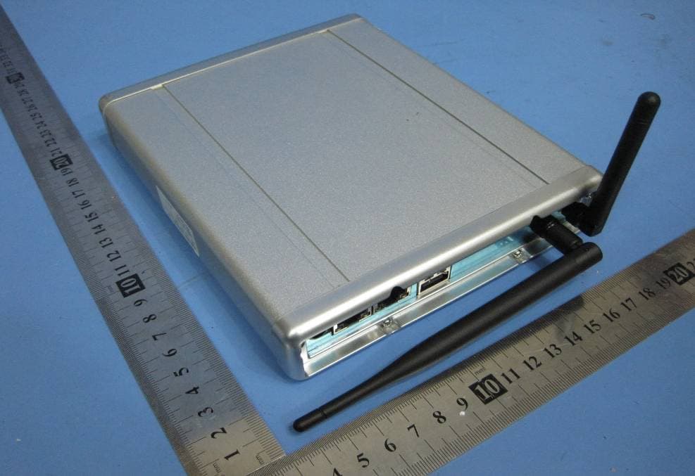
OU4-XG1000S-W
Jun 27, 2010WIFI GATEWAY
Equipment Class
DSC - Part 15 Security/Remote Control Transmitter
OU4-XCB80-FA
Feb 21, 2010FIRST ALERT BRIDGE
Equipment Class
DXX - Part 15 Low Power Communication Device Transmitter
OU4XPC260
Mar 21, 2007LAMP DIMMER
Equipment Class
DSC - Part 15 Security/Remote Control Transmitter
OU4XPC280
Mar 21, 2007GARAGE DOOR CONTROL
Equipment Class
DSC - Part 15 Security/Remote Control TransmitterOU4XG1000
Jul 12, 2006XANBOO REMOTE MONITORING AND ACCESS GATEWAY
Equipment Class
DSR - Part 15 Remote Control/Security Device Transceiver