OU4-XPC900XPC900 PCI Card and Auxiliary Unit
Xanboo, Inc.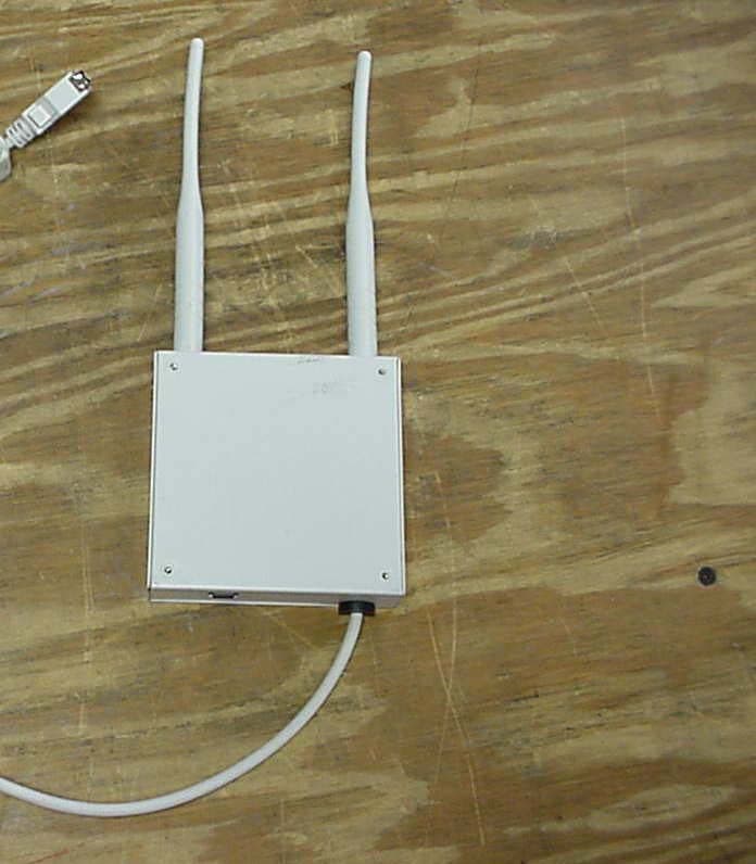
Click to zoom
Application Details
- Equipment Class
- DSR - Part 15 Remote Control/Security Device Transceiver
- Date of Grant
- Feb 16, 2004
- Application Purpose
- Original Equipment
- Date of Application
- Feb 16, 2004
- Equipment Note
- XPC900 PCI Card and Auxiliary Unit
- Frequency Range
- 418.00000000 - 418.00000000
- Company
- Xanboo, Inc.
- Country
- United States
Documents & Files
Document Text
Text extracted from the exhibit documents filed with the FCC. Open a document above to read the original.
Users Manual
Exhibit J: Users Manual Xanboo Model XPC900 PCI Card and Auxiliary Unit RF MODULE APPROVALS /// FCC ID NUMBER: OU4-XPC900-WAB / IC: 4576A STANDARDS 93/68/EEC, 89/336/EEC, BS EN 50082-1:1992, 73/23/EEC, EN60950:1992 CE IINSTRUCTIONS TO THE USER: The user is cautioned that changes and modifications made to the equipment without the approval of manufacturer could void the user's authority to operate this equipment. This equipment has been tested and found to comply with the limits for a class B digital device, pursuant to part 15 of the FCC Rules. These limits are designed to provide reasonable protection against harmful interference in a residential installation. This equipment generates, uses and can radiate radio frequency energy and if not installed and used in accordance with the instructions, may cause harmful interference to radio communications. However, there is no guarantee that interferences will not occur in a particular installation. If this equipment does cause harmful interference to radio or television reception, which can be determined by turning the equipment off and on, the user is encouraged to try to correct the interference by one or more of the following measures: • Reorient or relocate the receiving antenna. • Increase the separation between the equipment and receiver. • Connect the equipment into an outlet on a circuit different from that to which the receiver is connected. • Consult the dealer or an experienced radio/TV technician for help. CE directive 93/68/EEC, EMC directive 89/336/EEC, LV directive 73/23/EEC. This class B digital apparatus complies with Canadian ICES-003. The term “IC:” before the certification/registration number only signifies that the Industry Canada technical specifications were met. Operation is subject to the following two conditions: (1) this device may not cause interference, and (2) this device must accept any interference, including interference that may cause undesired operation of the device. PRODUCT DESCRIPTION /// The Shell HomeGenie ™ RF Module is a wireless auxiliary box for the XPC900-PCI card in the Shell HomeGenie ™ Gateway, which provides an external radio subsystem making for better RF performance. PACKAGE CONTENTS /// n (1) Shell HomeGenie ™ RF Module n (1) Tabletop Stand CONNECTING TO THE GATEWAY /// 1. Insert the the Shell HomeGenie ™ RF Module to the tabletop stand and secure the cable into the cable clip on the bottom of the base. 2. Plug the cable from the RF Module into the RF Module port on the back of the Gateway. 3. Make sure the locking clips have locked securely into place. 4. When the Gateway is powered up, the POWER light on the RF Module will turn green. I2 TECHNICAL SPECS /// n Supports AFM2 functionality n 418 MHz up to 100 feet range for indoor transmission n External radio subsystem makes for better RF performance n Indoor use only n Supports Shell HomeGenie ™ wireless cameras n Supports Shell HomeGenie ™ sensors (door, window, power, acoustic) n Supports Shell HomeGenie ™ thermostat POWER –X– LINK WIRELESS VIDEO VIDEO ACTIVE DATA SHELL HOMEGENIE RF MODULETABLETOP STAND CABLE CLIP OUT TO GATEWAY RF MODULE PORT POWER GREEN: ON NO LIGHT: OFF DATA SOLID GREEN: NO ACTIVITY BLINKING GREEN: WIRELESS ACTIVITY VIDEO ACTIVE GREEN: ONE OF THE CAMERAS IS POWERED (WEBCAM ACTIVE OR TAKING SNAPSHOT ORTAKING AUDIO/VIDEO CLIP) OFF: ALL CAMERAS ARE OFF –X– LINK BLINKING RED: BUNDLE DID NOT START YET RED: NO LINK TO BACKEND GREEN: COMMUNICATING WITH BACKEND OFF: BUNDLE STOPPED WIRELESS VIDEO (ONLY FOR WIRELESS CAMERAS) OFF: NO WIRELESS WEBCAMS ON (SCANNING FOR BEST CHANNEL) RED: VERY POOR VIDEO SIGNAL, WEBCAM MAY BE UNVIEWABLE YELLOW: MARGINAL VIDEO SIGNAL, WEBCAM SHOULD BE VIEWABLE GREEN: GOOD VIDEO SIGNAL, WEBCAM VIEWABLE
Block Diagram
Exhibit F: Block Diagram Xanboo Model XPC900 PCI Card and Auxiliary Unit
Cover Letter(s)
Exhibit K: Letter of Confidentiality Xanboo Model XPC900 PCI Card and Auxiliary Unit American Telecommunications Certification Body, Inc. 6731 Whittier Ave. McLean, VA 22101 February 6, 2004 RE: Certification Application FRN: 0007774151 FCC ID: OU4-XPC900 Please be advised the following information is to be held confidential on behalf of Company. • Schematics • Theory of operation Thank you, M Ghalebi Senior Vice president (Engineering)
Cover Letter(s)
Exhibit I: Letter of Authorization Xanboo Model XPC900 PCI Card and Auxiliary Unit
Cover Letter(s)
American Telecommunications Certification Body Inc. 6731 Whittier Ave, McLean, VA 22101 February 4, 2004 RE: FCC ID: OU4-XPC900 Attention: Mike Royer I have a few comments on this Application. 1. As part of the ATCB quality control and for help in tracking of an application, a competed 731 form is needed. Please note that the provided 731 does not list the equipment code for this application. Please provide the requested equipment code under section 4a of the 731. 2. Please provide the description of the device in section 4b of the 731 as it will be on the grant. Otherwise the name of this device as listed on the grant will be “XPC900 PCI Card and Auxiliary Unit”. 3. Please note that no letter of confidentiality has been provided, thus all exhibits will be open for public view. If you wish confidentiality of the schematics, block diagram and theory of operation, please submit a request for confidentiality letter. 4. Please note that the block diagram does not clearly indicate what the transmitter fundamental operating frequency is. It lists several frequencies, but does not specify the frequency delivered to the antenna. Please specify. 5. Please note that the operational description says that this is a receiver and does not mention an intentional radiator. Please provide an operational description of the intentional radiator part of this device. 6. Please show how you derived the ”averaging factor” shown in the data sheets (i.e. plots of the duty cycle over 100ms and the calculation etc). 7. Please note that you show a detector function of “Average” on the fundamental data sheets. Please note that 15.231 devices that are pulsed must use the averaging technique specified in 15.35, not the averaging function on the analyzer. Please explain. 8. On page 17 of the report, 232MHz has no limit listed. Please include the limit for this frequency in the table. 9. Please note that 15.231 devices using pulsed emissions must be averaged using the pulse width averaging technique specified in 15.35 and are not averaged using an average detector. This applies for all spurious emissions even those above 1GHz. Your report indicates that above 1GHz an average detector and not the averaging specified in 15.35 was used. Please also note that because of this and the fact that an average detector may yield a different value than the averaging method under 15.35, the actual peak value of several frequencies above 1GHz may actually exceed that of the fundamental and thus the corrected average and/or peak values for 1254MHz may fail. Please also not that under no circumstance can the peak, QP or average values of any emission exceed the recorded peak, QP or average value of the fundamental. Please report the peak readings of emissions above 1GHz and then use the calculated duty cycle averaging value to derive pulsed width averages. Alternately, please record all values of Peak and QP values for comparison to the requirement of 15.209c. 10. Please provide evidence that the device meets the automatic or manual turn off requirements of 15.231a2&3. This is generally done in the operational description. Dennis Ward mailto:[email protected] The items indicated above must be submitted before processing can continue on the above referenced application. Failure to provide the requested information may result in application termination. Correspondence should be considered part of the permanent submission and may be viewed from the Internet after a Grant of Equipment Authorization is issued. z Page 2 February 4, 2004 Please do not respond to this correspondence using the email reply button. In order for your response to be processed expeditiously, you must submit your documents through the AmericanTCB.com website. Also, please note that partial responses increase processing time and should not be submitted. Any questions about the content of this correspondence should be directed to the sender.
External Photos
Exhibit E2: EUT External Photos Xanboo Model XPC900 PCI Card and Auxiliary Unit Xanboo Model XPC900 PCI Card and Auxiliary Unit EUT External View Xanboo Model XPC900 PCI Card and Auxiliary Unit EUT External View
ID Label/Location Info
Exhibit C: Label Location Xanboo Model XPC900 PCI Card and Auxiliary Unit Xanboo Model XPC900 PCI Card and Auxiliary Unit
Internal Photos
Exhibit E1: EUT Internal Photos Xanboo Model XPC900 PCI Card and Auxiliary Unit Xanboo Model XPC900 PCI Card and Auxiliary Unit EUT Internal View Xanboo Model XPC900 PCI Card and Auxiliary Unit Xanboo Model XPC900 PCI Card and Auxiliary Unit
Test Report
Professional Testing (EMI), Inc. 1 Exhibit B: Test Report Xanboo Model XPC900 PCI Card and Auxiliary Unit Professional Testing (EMI) Inc. Report No. 04042-10 Page 2 of 21 Project Number: 04042-10 Prepared for: Xanboo 1626 Vineyard Grand Praire , TX 75052 By Professional Testing (EMI), Inc. 1601 FM 1460, Suite B Round Rock, Texas 78664 December 2003 CERTIFICATION Electromagnetic Interference Test Report Xanboo PCI Card and Auxilary Unit, Model XPC900 (Intentional Radiator Portion) Professional Testing (EMI) Inc. Report No. 04042-10 Page 3 of 21 Table of Contents Title Page .........................................................................................................................................1 Table of Contents .............................................................................................................................2 Certificate of Compliance ................................................................................................................3 1.0 EUT Description ......................................................................................................................5 1.1 EUT Operation.........................................................................................................................5 2.0 Electromagnetic Emissions Testing.........................................................................................6 2.1 Conducted Emissions Measurements ..................................................................................6 2.1.1 Test Procedure ................................................................................................................6 2.1.2 Test Criteria ....................................................................................................................6 2.1.3 Test Results .....................................................................................................................6 2.2 Radiated Emissions Measurements .....................................................................................7 2.2.1 Test Procedure ................................................................................................................7 2.2.2 Test Criteria ....................................................................................................................7 2.2.3 Test Results .....................................................................................................................8 3.0 Occupied Bandwidth Measurements .......................................................................................8 3.2 Test Criteria .........................................................................................................................8 3.3 Test Results ..........................................................................................................................8 4.0 Antenna Requirement ..............................................................................................................9 4.1 Evaluation Procedure ...........................................................................................................9 4.3 Evaluation Results ...............................................................................................................9 5.0 Modifications to Equipment ..................................................................................................10 6.0 List of Test Equipment...........................................................................................................10 Figures FIGURE 1: Conducted Emissions Mains Terminal Measurements ............................................. 11 FIGURE 2: Radiated Emissions Test Setup ................................................................................. 12 Appendices Appendix A: Emissions Data Sheet................................................................................................ 13 Appendix B: Occupied Bandwidth Data Sheets.............................................................................. 19 THIS REPORT SHALL NOT BE REPRODUCED EXCEPT IN FULL, WITHOUT THE WRITTEN APPROVAL OF PROFESSIONAL TESTING (EMI), INC. Professional Testing (EMI) Inc. Report No. 04042-10 Page 4 of 21 Applicant: Xanboo Applicant’s Address: 1626 Vineyard Grand Praire, TX 75052 FCC ID: OU4-XPC900 Project Number: 04042-10 Test Dates: July 7, 2003 I, Jeffrey A. Lenk, for Professional Testing (EMI), Inc., being familiar with the FCC rules and test procedures have reviewed the test setup, measured data and this report. I believe them to be true and accurate. The Xanboo, PCI Card and Auxilary Unit, Model XPC900 was tested to and found to be in compliance with FCC Part 15 Subpart C for an Intentional Radiator. The highest emissions generated by the above equipment are listed below: Frequency (MHz) Level (dBμV/m) Limit (dBμV/m) Margin (dB) Fundamental 418 72.9 80.3 -7.4 Spurious 158 40.1 40 0.1 Conducted 0.210 43 53 10 Occupied Bandwidth 0.578 ______________________________ Jeffrey A. Lenk President This report has been reviewed and accepted by Xanboo. The undersigned is responsible for ensuring that Xanboo, PCI Card and Auxilary Unit, Model XPC900 will continue to comply with the FCC rules. ______________________________ Certificate of Compliance Professional Testing (EMI) Inc. Report No. 04042-10 Page 5 of 21 1.0 EUT Description The Equipment under Test (EUT) is the Xanboo, PCI Card and Auxilary Unit, Model XPC900. The EUT is part of a security system. It provides a link from the security sensors to a personal computer. The unit is powered by a PCI card in the host computer, so that data and power can run in the same cable bundle. The EUT operates at 418 MHz and is designed for compliance with 47 CFR 15.231 of the FCC rules. Specific test requirements for this device include the following: 47 CFR 15.209 & 15.231 Fundamental Transmit Power 47 CFR 15.231 & 15.205 Spurious Radiated Power 47 CFR 15.231 Occupied Bandwidth 47 CFR 15.…
Text truncated - open the document above for the full version.
Test Setup Photos
Exhibit D: Test Setup Photos Xanboo Model XPC900 PCI Card and Auxiliary Unit Xanboo Model XPC900 PCI Card and Auxiliary Unit Conducted Emissions Test Setup Xanboo Model XPC900 PCI Card and Auxiliary Unit Radiated Emissions Test Setup
Contact Information
Applicant
Kent E Britain(Sr. RF Engineer)
Technical Contact
Professional Testing (EMI) Inc.Mike Royer
[email protected](512) 244 3371
1601 FM 1460, Suite B · Round Rock, Texas · United States
Test Firm
Professional Testing (EMI), Inc.Jeff Link
Technical Specifications
| # | Rule Parts | Frequency Range | Power Output |
|---|---|---|---|
| 1 | 15.231 | 418 MHz - 418 MHz | - |
Other Applications from Xanboo, Inc.
OU4-XG1000S-W
Jun 27, 2010WIFI GATEWAY
Equipment Class
DSC - Part 15 Security/Remote Control Transmitter
OU4-XCB80-FA
Feb 21, 2010FIRST ALERT BRIDGE
Equipment Class
DXX - Part 15 Low Power Communication Device Transmitter
OU4XPC260
Mar 21, 2007LAMP DIMMER
Equipment Class
DSC - Part 15 Security/Remote Control Transmitter
OU4XPC280
Mar 21, 2007GARAGE DOOR CONTROL
Equipment Class
DSC - Part 15 Security/Remote Control TransmitterOU4XG1000
Jul 12, 2006XANBOO REMOTE MONITORING AND ACCESS GATEWAY
Equipment Class
DSR - Part 15 Remote Control/Security Device Transceiver