OU4-XWC900Mcam XWC900 Security Camera Transmitter
Xanboo, Inc.
Click to zoom
Application Details
- Equipment Class
- DXX - Part 15 Low Power Communication Device Transmitter
- Date of Grant
- May 24, 2004
- Application Purpose
- Original Equipment
- Date of Application
- May 24, 2004
- Equipment Note
- Mcam XWC900 Security Camera Transmitter
- Frequency Range
- 2470.00000000 - 2470.00000000
- Company
- Xanboo, Inc.
- Country
- United States
Documents & Files
Document Text
Text extracted from the exhibit documents filed with the FCC. Open a document above to read the original.
Users Manual
Exhibit J: Users Manual Xanboo Mcam XWC900 Security Camera Transmitter
Block Diagram
Exhibit F: Block Diagram Xanboo Mcam XWC900 Security Camera Transmitter
Cover Letter(s)
Exhibit K: Letter of Confidentiality Xanboo Mcam XWC900 Security Camera Transmitter
Cover Letter(s)
Exhibit I: Letter of Authorization Xanboo Mcam XWC900 Security Camera Transmitter
Cover Letter(s)
American Telecommunications Certification Body Inc. 6731 Whittier Ave, McLean, VA 22101 May 17, 2004 RE: FCC ID: OU4-XWC900_ATCB001348 Attention: Mike Royer I have a few comments on this Application. 1. Please note that you have provided the wrong test report. The report provided is for the XWS50M Motion Sensor. Please provide the report for the XWC900. 2. Please provide internal photos showing the tops and bottoms of all boards. Please disassemble the internal boards so this is possible. 3. Please provide the schematics for this device. Dennis Ward mailto:[email protected] The items indicated above must be submitted before processing can continue on the above referenced application. Failure to provide the requested information may result in application termination. Correspondence should be considered part of the permanent submission and may be viewed from the Internet after a Grant of Equipment Authorization is issued. Please do not respond to this correspondence using the email reply button. In order for your response to be processed expeditiously, you must submit your documents through the AmericanTCB.com website. Also, please note that partial responses increase processing time and should not be submitted. Any questions about the content of this correspondence should be directed to the sender.
Cover Letter(s)
American Telecommunications Certification Body Inc. 6731 Whittier Ave, McLean, VA 22101 May 24, 2004 RE: FCC ID: OU4-XWC900_ATCB001348 Attention: Mike Royer I have a few comments on this Application. 1. Please note that 15.249 is an average limit above 1GHz. Please note that the test report indicates the measurement distance is 3 meter (page 16). Please also note that since the measurement distance was 3 meters the 20dB over peak would be 113.5 not 123.5dBuV/m. It is not sufficient to state that you passed the 20dB over the average limit as you must first comply with the actual average limit. The use of peak measurements alone is only valid when the peak measurement does not exceed the average limit. If it does then mandatory peak and average measurements must be made to show compliance to both the average limit and the 20dB over average limits for peak. Please note that as an average of the vertical 101.6dBuV/m reading has not been done, the device is considered to fail. Please provide the required comparison to the averaged limit of 93.5dBuV/m to 15.249. 2. Please note that the report states, “The transmitter automatically shuts off following the 19mS encoded message”. However, it does not appear that it has been made that the device shuts off for the minimum mandatory time set in 15.231e. Please provide clarification on this issue in the report 3. FYI – no action needed. When no spurious emissions are found, it is good practice to at least report the noise floor on several readings to confirm the noise floor is not masking potential failing readings. Dennis Ward mailto:[email protected] The items indicated above must be submitted before processing can continue on the above referenced application. Failure to provide the requested information may result in application termination. Correspondence should be considered part of the permanent submission and may be viewed from the Internet after a Grant of Equipment Authorization is issued. Please do not respond to this correspondence using the email reply button. In order for your response to be processed expeditiously, you must submit your documents through the AmericanTCB.com website. Also, please note that partial responses increase processing time and should not be submitted. Any questions about the content of this correspondence should be directed to the sender.
Cover Letter(s)
Dennis Ward From: Michael Royer [[email protected]] Sent: Monday, May 24, 2004 3:08 PM To: [email protected] Subject: ou4-xwc900 5/24/2004 Hi Dennis Regarding the comments 1. The test was actually done at 1m distance and the average data was excluded. The data sheet is updated. 2. We have corrected the report to include the turn back on delay. 3. Thanks, will do. I will be with a client tomorrow, but Kristi should be uploading the corrections in the morning. Mike --- Outgoing mail is certified Virus Free. Checked by AVG anti-virus system (http://www.grisoft.com). Version: 6.0.665 / Virus Database: 428 - Release Date: 4/21/2004
External Photos
Exhibit E1 – External EUT Photo Xanboo Mcam XWC900 Security Camera Transmitter Xanboo Mcam XWC900 Security Camera Transmitter
ID Label/Location Info
Exhibit C: Label Location Xanboo Mcam XWC900 Security Camera Transmitter Xanboo Mcam XWC900 Security Camera Transmitter
Internal Photos
Exhibit E2 – Internal EUT Photo Xanboo Mcam XWC900 Security Camera Transmitter Xanboo Mcam XWC900 Security Camera Transmitter Xanboo Mcam XWC900 Security Camera Transmitter Xanboo Mcam XWC900 Security Camera Transmitter
Internal Photos
Exhibit E3 – Internal EUT Photo Xanboo Mcam XWC900 Security Camera Transmitter Xanboo Mcam XWC900 Security Camera Transmitter
Test Report
Professional Testing (EMI), Inc. Report No. 04442-10 Page 1 of 21 Exhibit B: Test Report Xanboo Mcam XWC900 Security Camera Transmitter Professional Testing (EMI), Inc. Report No. 04442-10 Page 2 of 21 Project Number: 04442-10 Prepared for: Xanboo 1626 Vineyard Grand Praire , TX 75052 By Professional Testing (EMI), Inc. 1601 FM 1460, Suite B Round Rock, Texas 78664 May 2004 CERTIFICATION Electromagnetic Interference Test Report Xanboo Mcam XWC900 Security Camera (Intentional Radiator Portion) Professional Testing (EMI), Inc. Report No. 04442-10 Page 3 of 21 Table of Contents Title Page .........................................................................................................................................1 Table of Contents .............................................................................................................................2 Certificate of Compliance ................................................................................................................3 Table of Contents .............................................................................................................................3 1.0 EUT Description ..................................................................................................................5 1.1 EUT Operation.....................................................................................................................5 2.0 Electromagnetic Emissions Testing.....................................................................................5 2.1 Conducted Emissions Measurements ..............................................................................5 2.1.1 Test Procedure .........................................................................................................6 2.1.2 Test Criteria .............................................................................................................6 2.1.3 Test Results ..............................................................................................................6 2.2 Radiated Emissions Measurements .................................................................................6 2.2.1 Test Procedure .........................................................................................................7 2.2.2 Test Criteria .............................................................................................................7 2.2.3 Test Results ..............................................................................................................8 3.0 Occupied Bandwidth Measurements ...................................................................................8 3.2 Test Criteria .....................................................................................................................8 3.3 Test Results ......................................................................................................................8 4.0 Antenna Requirement ..........................................................................................................9 4.1 Evaluation Procedure .......................................................................................................9 4.3 Evaluation Results ...........................................................................................................9 5.0 Modifications to Equipment ..............................................................................................10 6.0 List of Test Equipment.......................................................................................................10 Figures FIGURE 1: Conducted Emissions Mains Terminal Measurements ............................................. 11 FIGURE 2: Radiated Emissions Test Setup ................................................................................. 12 Appendices Appendix A: Emissions Data Sheet ...............................................................................................13 Appendix B: Occupied Bandwidth Data Sheets............................................................................. 18 THIS REPORT SHALL NOT BE REPRODUCED EXCEPT IN FULL, WITHOUT THE WRITTEN APPROVAL OF PROFESSIONAL TESTING (EMI), INC. Professional Testing (EMI), Inc. Report No. 04442-10 Page 4 of 21 Applicant: Xanboo Applicant’s Address: 1626 Vineyard Grand Praire, TX 75052 FCC ID: OU4-XWC900 Project Number: 03376-10 Test Dates: March 20, 2003 I, Jeffrey A. Lenk, for Professional Testing (EMI), Inc., being familiar with the FCC rules and test procedures have reviewed the test setup, measured data and this report. I believe them to be true and accurate. The Xanboo, Mcam XWC900 Security Camera Transmitter was tested to and found to be in compliance with FCC Part 15 Subpart C for an Intentional Radiator. The highest emissions generated by the above equipment are listed below: Frequency (MHz) Level (dBμV/m) Limit (dBμV/m) Margin (dB) Fundamental 2470 100.8 103.5 -1.9 418 79.8 80.3 -0.5 Spurious 4940 46.7 63.5 -0.1 Conducted 0.15 44.1 66.0 -21.9 Occupied Bandwidth 121 (kHz) 1.045 (MHz) ______________________________ Jeffrey A. Lenk President This report has been reviewed and accepted by Xanboo. The undersigned is responsible for ensuring that Xanboo, Mcam XWC900 Security Camera Transmitter will continue to comply with the FCC rules. Certificate Of Compliance Professional Testing (EMI), Inc. Report No. 04442-10 Page 5 of 21 1.0 EUT Description The Mcam XWC900 Security Camera Transmitter (EUT) is a remotely controlled surveillance camera. The (EUT) contains a Passive Infra Red detector. When the PIR detects a person, it transmits the unit’s unique ID number and action code on 418 MHz to the Xanboo system. If so programmed, the Xanboo System will tell the (EUT) to turn on its video camera and 2.4 GHz transmitter. The owner can then monitor the video, or screen captured and emailed to the owner. The (EUT) can also be commanded on. The 418 MHz signal is a 19mS long …
Text truncated - open the document above for the full version.
Test Setup Photos
Exhibit D – Test Setup Photographs Xanboo Mcam XWC900 Security Camera Transmitter Xanboo Mcam XWC900 Security Camera Transmitter Conducted Emissions Test Setup Xanboo Mcam XWC900 Security Camera Transmitter Radiated Emissions Test Setup
Contact Information
Applicant
Kent E Britain(Sr. RF Engineer)
Technical Contact
Professional Testing (EMI) Inc.Mike Royer
[email protected](512) 244 3371
1601 FM 1460, Suite B · Round Rock, Texas · United States
Test Firm
Professional Testing (EMI), Inc.Michael Royer
Technical Specifications
| # | Rule Parts | Frequency Range | Power Output |
|---|---|---|---|
| 1 | 15C | 2.47 GHz - 2.47 GHz | - |
Other Applications from Xanboo, Inc.
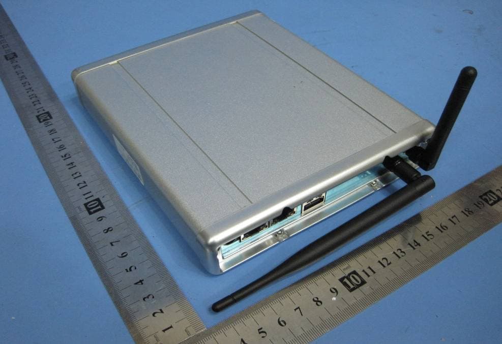
OU4-XG1000S-W
Jun 27, 2010WIFI GATEWAY
Equipment Class
DSC - Part 15 Security/Remote Control Transmitter
OU4-XCB80-FA
Feb 21, 2010FIRST ALERT BRIDGE
Equipment Class
DXX - Part 15 Low Power Communication Device Transmitter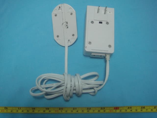
OU4XPC260
Mar 21, 2007LAMP DIMMER
Equipment Class
DSC - Part 15 Security/Remote Control Transmitter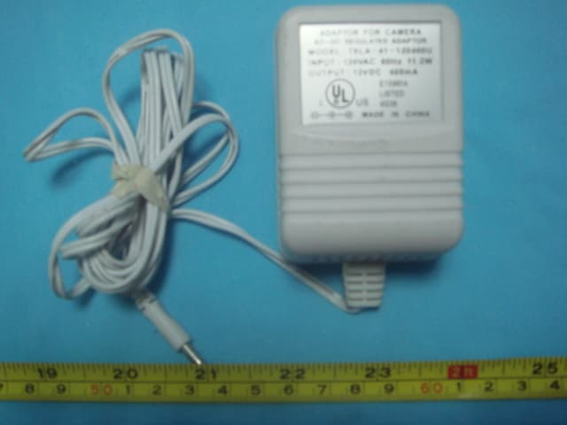
OU4XPC280
Mar 21, 2007GARAGE DOOR CONTROL
Equipment Class
DSC - Part 15 Security/Remote Control TransmitterOU4XG1000
Jul 12, 2006XANBOO REMOTE MONITORING AND ACCESS GATEWAY
Equipment Class
DSR - Part 15 Remote Control/Security Device Transceiver