OU4-XWS50MMotion Detector Transmitter
Xanboo, Inc.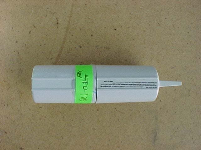
Click to zoom
Application Details
- Equipment Class
- DSC - Part 15 Security/Remote Control Transmitter
- Date of Grant
- May 16, 2004
- Application Purpose
- Original Equipment
- Date of Application
- May 16, 2004
- Equipment Note
- Motion Detector Transmitter
- Frequency Range
- 418.00000000 - 418.00000000
- Company
- Xanboo, Inc.
- Country
- United States
Documents & Files
Document Text
Text extracted from the exhibit documents filed with the FCC. Open a document above to read the original.
Users Manual
Exhibit J: Users Manual Xanboo XWS50M Motion Sensor Transmitter
Block Diagram
Exhibit F: Block Diagram Xanboo XWS50M Motion Detector Transmitter
Cover Letter(s)
Exhibit K: Letter of Authorization Xanboo XWS50M Motion Sensor Transmitter
Cover Letter(s)
Exhibit I: Letter of Authorization Xanboo XWS50M Motion Sensor Transmitter
Cover Letter(s)
American Telecommunications Certification Body Inc. 6731 Whittier Ave, McLean, VA 22101 May 13, 2004 RE: FCC ID: OU4-XWS50M_ATCB001335 Attention: Mike Royer I have a few comments on this Application. 1. Please note that the 731 only addresses the 418MHz transmitter under 15.231. The report indicates that there are two transmitters in this device, one 418MHz and 2.4GHz. In this case the application would be a composite under two distinct scopes (A1 and A2). Also, please note that the test report does not address the 2.4GHz transmitter Under 15.249. If this is part of a composite application that is already at the FCC or already granted, please verify. Otherwise, please explain and please provide the necessary data for compliance. 2. Please note that you use incorrect limits for the field strength limits on page 12 of the report. The test distance is said to be 3 meters. AT 418MHz 15.231 limits would be 80.2uV/m. Please correct your report to compare measured values to the correct limits for 3 meters. 3. Please note that your duty cycle plot is not in accordance with 15.35 which states that the pulse train is to be measured over 100ms. Please note that you have only shown 50ms. Please provide a corrected plot showing the full 100ms reference sweep time. 4. Please note that the device appears to fail radiated spurious emissions at 1254MHz. Please note that 20log(1250uV/m) is 61.9dBuV not 63.5dBuV. Even if the limit is rounded off to 62dBuV/m the margin would then be 0dB. However, since the 20log number is less than the measured, technically the device fails. The device is most likely compliant when the pulse width duty cycle averaging is done. However, as this was not provided the measured peak must be used in evaluating the product. Please provide results showing clear compliance of the device using pulse width duty cycle averaging. Also, please derive this factor using the required 100ms time frame and not 50ms. Dennis Ward mailto:[email protected] The items indicated above must be submitted before processing can continue on the above referenced application. Failure to provide the requested information may result in application termination. Correspondence should be considered part of the permanent submission and may be viewed from the Internet after a Grant of Equipment Authorization is issued. Please do not respond to this correspondence using the email reply button. In order for your response to be processed expeditiously, you must submit your documents through the AmericanTCB.com website. Also, please note that partial responses increase processing time and should not be submitted. Any questions about the content of this correspondence should be directed to the sender.
Cover Letter(s)
Dennis Ward From: Michael Royer [[email protected]] Sent: Thursday, May 13, 2004 12:08 PM To: [email protected] Subject: RE: OU4-XWS50M_ATCB001335 5/14/2004 Hi Dennis, Thank you for your comments. I have reviewed them and have a quick reply. To be followed by an upload soon. 1. There is no 2.4 GHz transmitter in this device. The sentence in the report on page 5 referring to the video transmitter will be removed. 2. The field strength limits used are for 15.231 e). Xanboo did not want to wait for an hour between system integrity checks, and so accepted the lower transmit limit of paragraph e. I used the general limit for spurious, but will change that to 52.3 dBuV/m and use the 12.4 dB average relaxation to show compliance. 3. I did not consider the need to make the plots 100mS long. I selected 50mS to clearly show the on time. Can you take a written statement that the product does not turn back on during the 100mS, or for several minutes? The sample I kept here at the lab is a continuous transmit sample. 4. I will change the limit to 52.3 dBuV/m, and apply the 12.4 dB averaging factor. I will write you when we update the file. Best regards, Mike Royer -----Original Message----- From: dward ATCB [mailto:[email protected]] Sent: Thursday, May 13, 2004 12:26 PM To: [email protected] Subject: OU4-XWS50M_ATCB001335 Hi Mike Please see comments Thanks Dennis --- Incoming mail is certified Virus Free. Checked by AVG anti-virus system (http://www.grisoft.com). Version: 6.0.665 / Virus Database: 428 - Release Date: 4/21/2004 --- Outgoing mail is certified Virus Free. Checked by AVG anti-virus system (http://www.grisoft.com). Version: 6.0.665 / Virus Database: 428 - Release Date: 4/21/2004
External Photos
Exhibit E1 – External EUT Photo Xanboo XWS50M Motion Sensor Transmitter Xanboo XWS50M Motion Sensor Transmitter Xanboo XWS50M Motion SensorTransmitter
ID Label/Location Info
Exhibit C: Label Location Xanboo XWS50M Motion Sensor Transmitter
Internal Photos
Exhibit E2 – Internal EUT Photo Xanboo XWS50M Motion Sensor Transmitter Xanboo Security Camera, Model XWC700 XWS50M Motion Sensor Transmitter Xanboo Security Camera, Model XWC700 XWS50M Motion Sensor Transmitter
Test Report
Professional Testing (EMI), Inc. Report No. 04447-10 Page 1 of 17 Exhibit B: Test Report Xanboo XWS50M Motion Detector Transmitter Professional Testing (EMI), Inc. Report No. 04447-10 Page 2 of 17 Project Number: 04447-10 Prepared for: Xanboo 400 Columbus Avenue Valhaua , New York 10595 By Professional Testing (EMI), Inc. 1601 FM 1460, Suite B Round Rock, Texas 78664 May 2004 CERTIFICATION Electromagnetic Interference Test Report Xanboo XWS50M Motion Detector Transmitter (Intentional Radiator Portion) Professional Testing (EMI), Inc. Report No. 04447-10 Page 3 of 17 Table of Contents Title Page .........................................................................................................................................1 Table of Contents .............................................................................................................................2 Certificate of Compliance ................................................................................................................3 Table of Contents .........................................................................................................................3 1.0 EUT Description ..................................................................................................................5 1.1 EUT Operation.....................................................................................................................5 2.0 Electromagnetic Emissions Testing.....................................................................................5 2.1 Radiated Emissions Measurements .................................................................................5 2.1.1 Test Procedure .........................................................................................................6 2.1.2 Test Criteria .............................................................................................................6 2.1.3 Test Results ..............................................................................................................6 3.0 Occupied Bandwidth Measurements ...................................................................................6 3.2 Test Criteria .....................................................................................................................7 3.3 Test Results ......................................................................................................................7 4.0 Antenna Requirement ..........................................................................................................8 4.1 Evaluation Procedure .......................................................................................................8 4.3 Evaluation Results ...........................................................................................................8 5.0 Modifications to Equipment ................................................................................................9 6.0 List of Test Equipment.........................................................................................................9 Figures FIGURE 1 Radiated Emissions Test Setup ................................................................................. 10 Appendices Appendix A Emissions Data Sheet......................................................................................... 11 Appendix B Occupied Bandwidth Data Sheets ...................................................................... 15 THIS REPORT SHALL NOT BE REPRODUCED EXCEPT IN FULL, WITHOUT THE WRITTEN APPROVAL OF PROFESSIONAL TESTING (EMI), INC. Professional Testing (EMI), Inc. Report No. 04447-10 Page 4 of 17 Applicant: Xanboo Applicant’s Address: 400 Columbus Avenue Valhaua, New York 10595 FCC ID: OU4-XWS50M Project Number: 04447-10 Test Dates: April 14, 2004, April 15, 2004 I, Jeffrey A. Lenk, for Professional Testing (EMI), Inc., being familiar with the FCC rules and test procedures have reviewed the test setup, measured data and this report. I believe them to be true and accurate. The Xanboo, XWS50M Motion Detector Transmitter was tested to and found to be in compliance with FCC Part 15 Subpart C for an Intentional Radiator. The highest emissions generated by the above equipment are listed below: Frequency (MHz) Level (dBμV/m) Limit (dBμV/m) Margin (dB) Fundamental 418 70.3 72.3 -2.0 Occupied Bandwidth 136 (kHz) 1.045 (MHz) ______________________________ Jeffrey A. Lenk President This report has been reviewed and accepted by Xanboo. The undersigned is responsible for ensuring that Xanboo, XWS50M Motion Detector Transmitter will continue to comply with the FCC rules. ______________________________ Certificate of Compliance Professional Testing (EMI), Inc. Report No. 04447-10 Page 5 of 17 1.0 EUT Description The Equipment under Test (EUT) is the Xanboo, XWS50M Motion Detector Transmitter. The XWS50M Motion Detector Transmitter is a Passive Infra Red detector compatible with the protocols of the Xanboo system. In normal use the XWS50M would be placed in a semi concealed location with a view of the owners car, gate, front door, etc. When an Infra Red event is detected, th XWS50M transmits it’s unique ID code on 418 MHz to the Xanboo system.: 47 CFR 15.231e Fundamental Transmit Power 47 CFR 15.231e Occupied Bandwidth 47 CFR 15.203 Antenna Requirement The system tested consisted of the following: Manufacturer & Model Serial # FCC ID # Description Xanboo, XWS50M Motion Detector Transmitter N/A OU4-XWS50M Motion Sensor Transmitter 1.1 EUT Operation The Xanboo XWS50M Motion Detector Transmitter was tested using internal batteries. The frequency of the transmitting television signal is 2470 MHz. This signal is transmitted continuously. The Infrared Motion Sensor Transmitter operating at 418 MHz under normal configuration can only be triggered once per fifteen seconds and transmits a recognition code for 24 milliseconds. For the purpose of testing, a special mode was used, for most …
Text truncated - open the document above for the full version.
Test Setup Photos
Exhibit D – Test Setup Photographs Xanboo XWS50M Motion Sensor Transmitter Xanboo XWS50M Motion Sensor Transmitter Radiated Emissions Test Setup
Contact Information
Applicant
Kent E Britain(Sr. RF Engineer)
Technical Contact
Professional Testing (EMI) Inc.Mike Royer
[email protected](512) 244 3371
1601 FM 1460, Suite B · Round Rock, Texas · United States
Test Firm
Professional Testing (EMI), Inc.Michael Royer
Technical Specifications
| # | Rule Parts | Frequency Range | Power Output |
|---|---|---|---|
| 1 | 15.231(e) | 418 MHz - 418 MHz | - |
Other Applications from Xanboo, Inc.
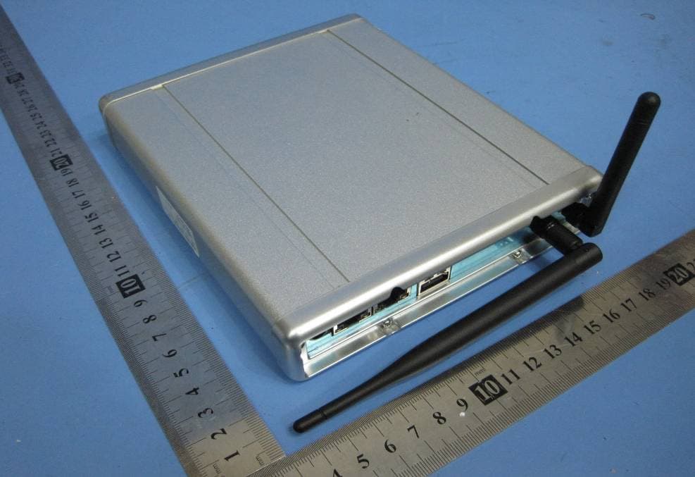
OU4-XG1000S-W
Jun 27, 2010WIFI GATEWAY
Equipment Class
DSC - Part 15 Security/Remote Control Transmitter
OU4-XCB80-FA
Feb 21, 2010FIRST ALERT BRIDGE
Equipment Class
DXX - Part 15 Low Power Communication Device Transmitter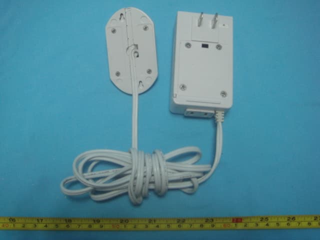
OU4XPC260
Mar 21, 2007LAMP DIMMER
Equipment Class
DSC - Part 15 Security/Remote Control Transmitter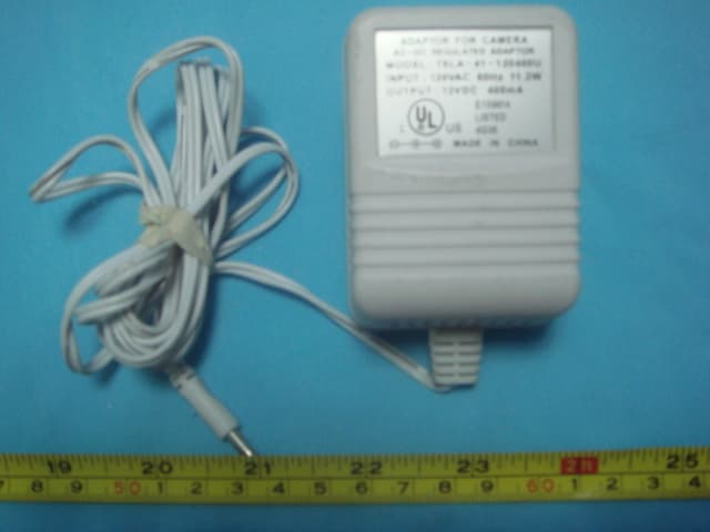
OU4XPC280
Mar 21, 2007GARAGE DOOR CONTROL
Equipment Class
DSC - Part 15 Security/Remote Control TransmitterOU4XG1000
Jul 12, 2006XANBOO REMOTE MONITORING AND ACCESS GATEWAY
Equipment Class
DSR - Part 15 Remote Control/Security Device Transceiver