OU4TX240V2.4 GHz Wireless Security Video Camera
Xanboo, Inc.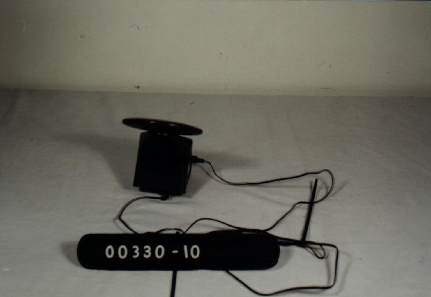
Click to zoom
Application Details
- Equipment Class
- DXX - Part 15 Low Power Communication Device Transmitter
- Date of Grant
- Apr 17, 2000
- Application Purpose
- Original Equipment
- Date of Application
- Jan 19, 2000
- Equipment Note
- 2.4 GHz Wireless Security Video Camera
- Frequency Range
- 2.43200000 - 2.43200000
- Company
- Xanboo, Inc.
- Country
- United States
Documents & Files

Document Text
Text extracted from the exhibit documents filed with the FCC. Open a document above to read the original.
Operational Description
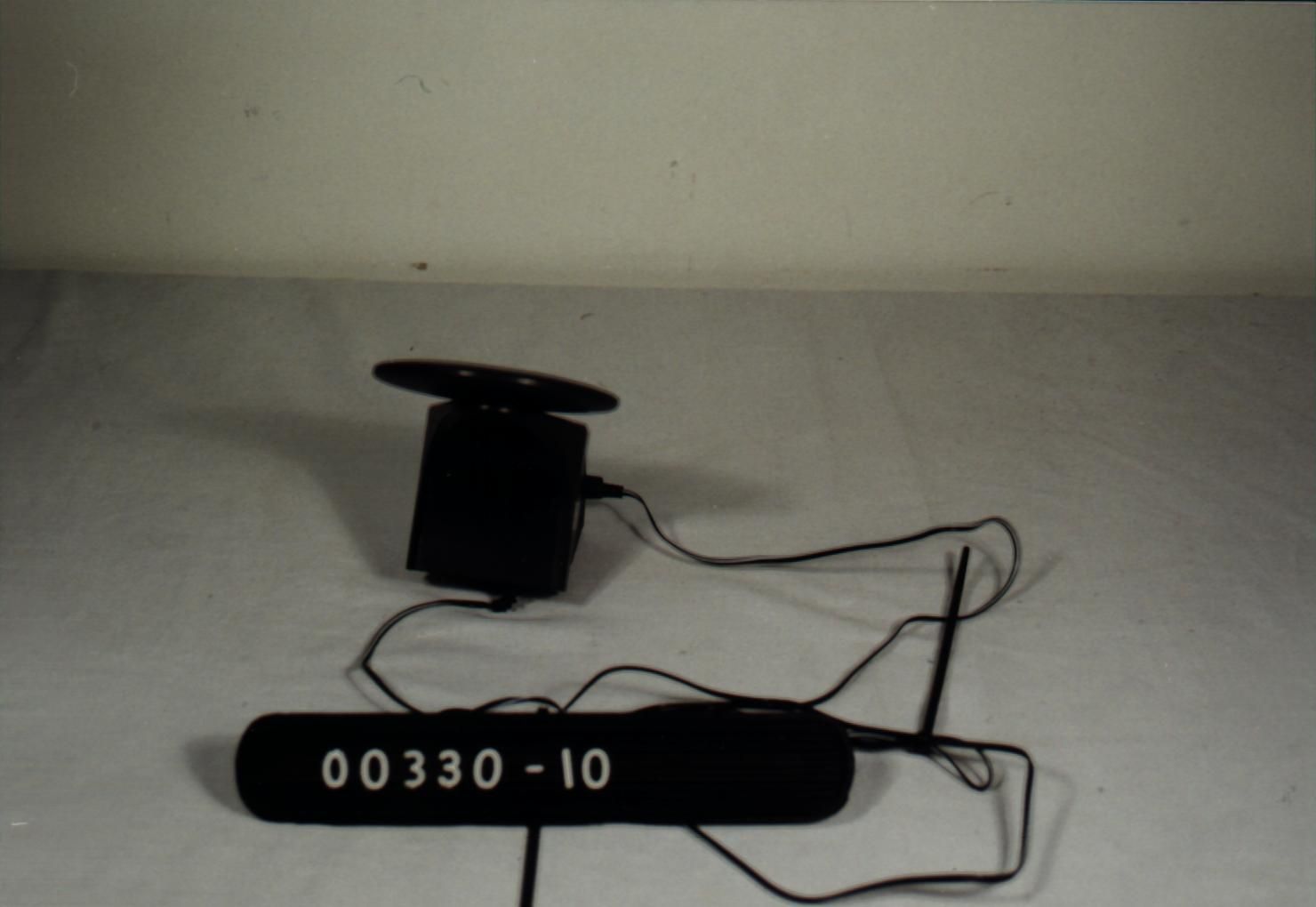
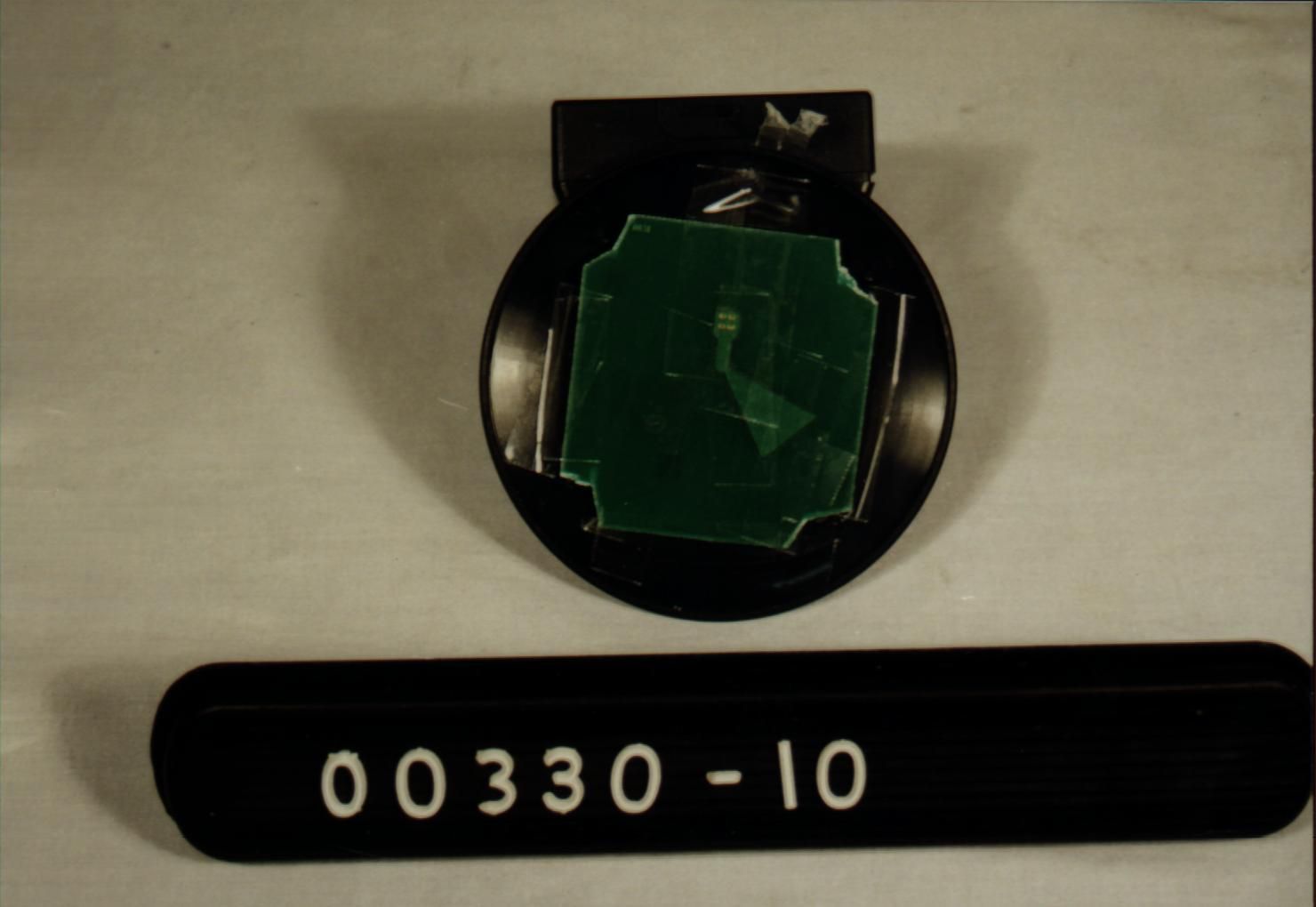
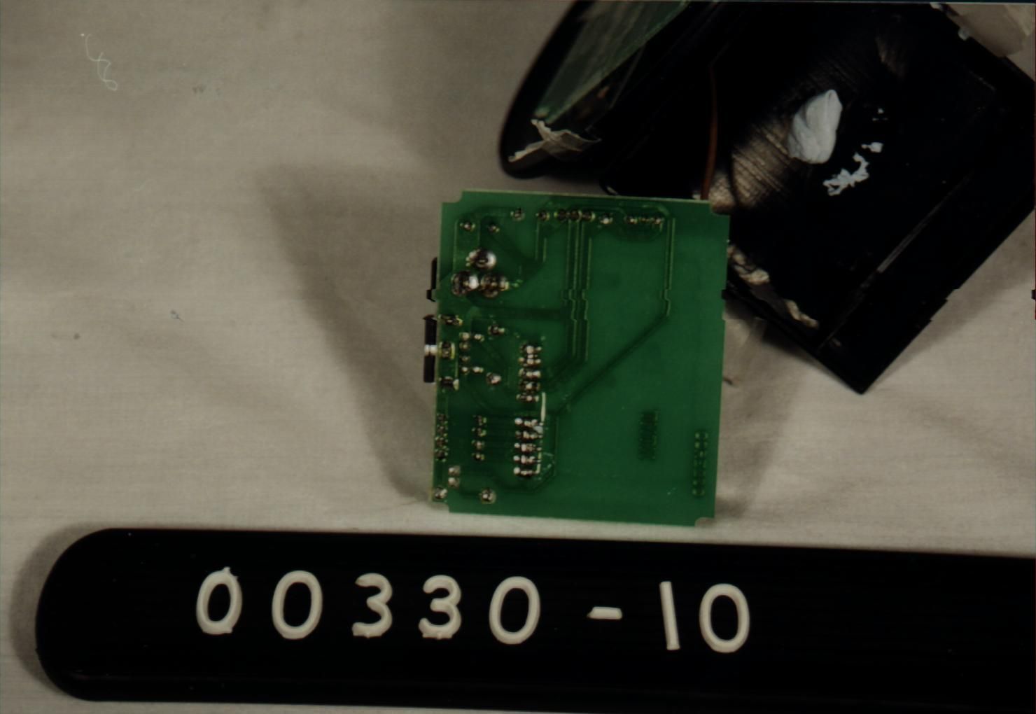
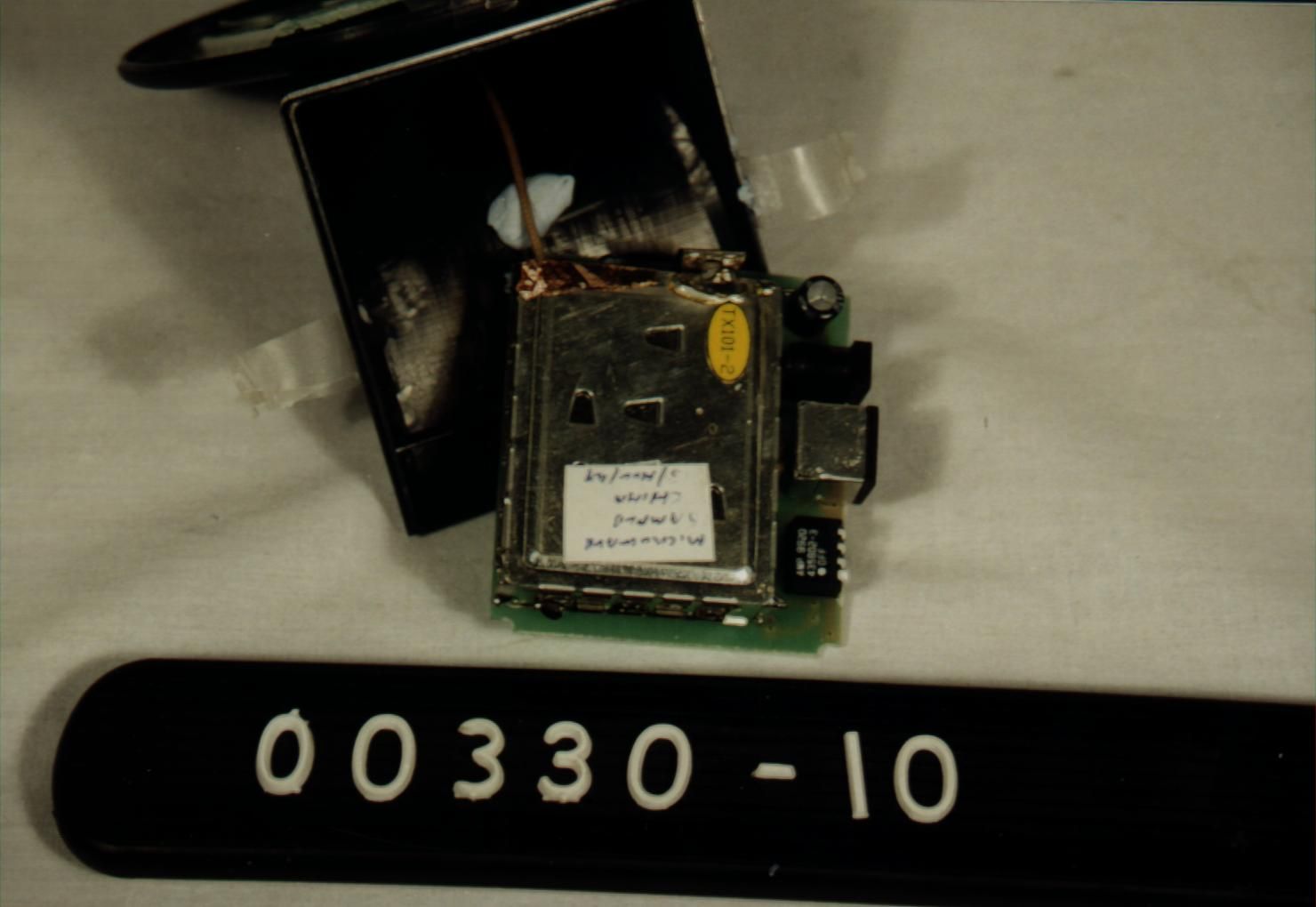
Theory of Operation: OU4TX240V The TX240V is a low power video monitoring system aimed at the home and commercial markets. The TX240V consists of 3 components, a CMOS TV camera, the combination 2.4 GHz transmitter with integral antenna, and a 12 volt linear power supply. The CMOS TV camera uses a non-standard video connector and is designed to work only with it's companion transmitter. Video output is the normal 1 volt p-p NTSC Video signal. The camera is designed to contain a microphone, but after recent court rulings on 'serendipitous recordings' the microphone will not be included at this time. The transmitter consists of a commercial 2.4 GHz module. The module phase locks to a 4.000 MHz crystal to directly generate a 2.4 GHz signal. The phase lock has a relatively slow lock time, this allows the video signal to be directly applied to the VCO generating the 2.4 GHz FM Video signal. A separate 5.5 MHz VCO is modulated by the incoming audio and also directly applied to the 2.4 GHz VCO generating a 5.5 MHz audio sub-carrier. The 2.4 GHz modulated signal is then amplified, passes through a 5 pole PCB filter, is amplified to the 0 dBm level and passes though a second 1 pole PCB filter. The 0 dBm output is radiated by a horizontally polarized dipole antenna etched on a PC Board. The connections between the transmitter and the antenna are directly soldered, no connectors are used. The power supply is a 12 VDC 500 ma linear supply of the wall mount variety. The 12 VDC supply plugs into the transmitter section. The 12 VDC is then wired directly to the CMOS TV camera and to a 7808 voltage regulator. The eight Volts DC from the regulator is supplied to the 2.4 GHz module. SPECIFICATIONS: Video Input: 1 Volt P-P, NTSC RF Power Output: 0 dBm Antenna: Dipole Response to FCC 15-203 Antenna/Transmitter Connection, RG-174, all connections directly soldered. Frequency 2.415 GHz. Emission FM Modulated NTSC Video Audio Sub-carrier 5.5 MHz (Not used) Occupied Bandwidth 12.7 MHz 12M7F8F
Schematics
FCC ID: OU4TX240V FCC ID: OU4TX240V
Test Report
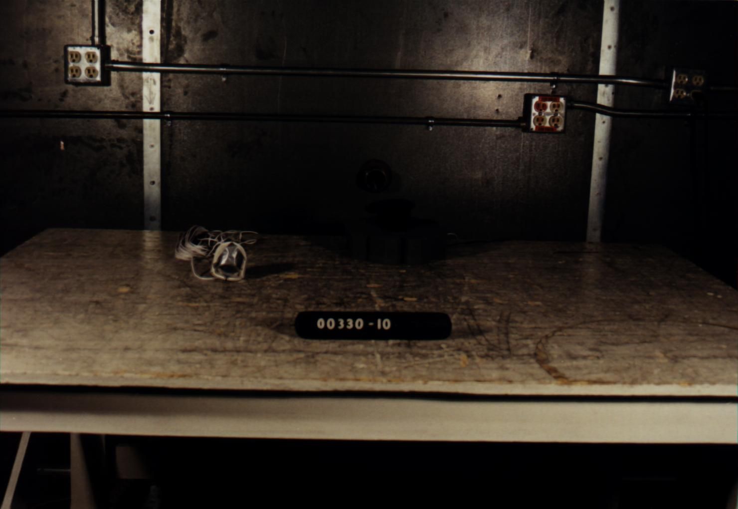
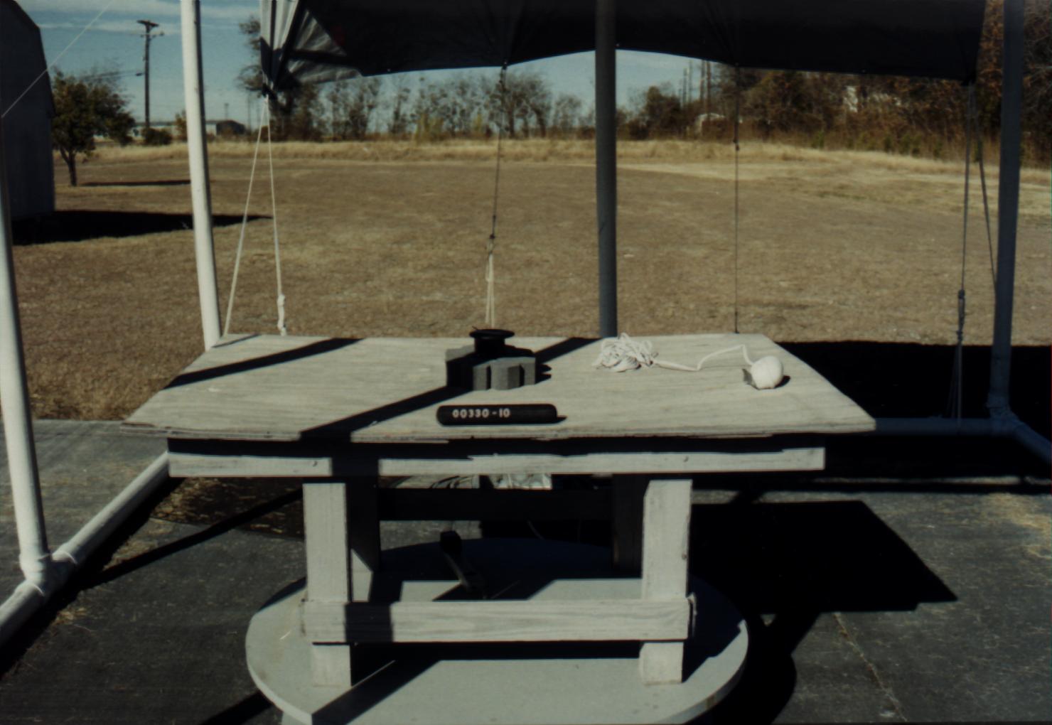
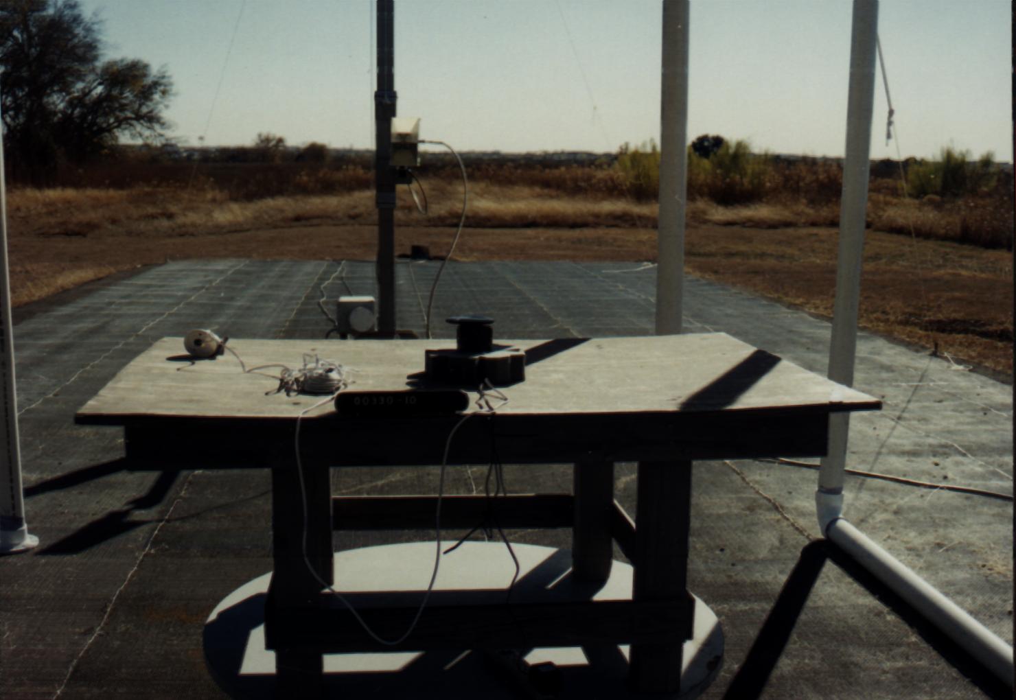
FCC ID# OU4TX240V Project Number: 00330-10 Prepared for: CORE TECHNOLOGY 1626 Vineyard Grand Prairie Texas 75058 By Professional Testing (EMI), Inc. 1601 FM 1460, Suite B Round Rock, Texas 78664 January 2000 CERTIFICATION Electromagnetic Interference Test Report CORE TECHNOLOGY TX240V Transmitter Operating with The CTR241 Wireless Home Observation System (Intentional Radiator Portion) FCC ID# OU4TX240V Professional Testing (EMI), Inc.Page 2 of 15 Table of Contents Title Page......................................................................................................................................... 1 Table of Contents ............................................................................................................................ 2 Certificate of Compliance ............................................................................................................... 3 1.0 EUT Description ...................................................................................................................... 4 1.1 EUT Operation ........................................................................................................................ 4 2.0 Electromagnetic Emissions Testing ......................................................................................... 4 2.1 Test Procedure..................................................................................................................... 5 2.2 Test Criteria .................................................................................................................... ....5 2.3 Test Results ......................................................................................................................... 5 3.0 Occupied Bandwidth Measurements....................................................................................... 5 3.1 Test Procedure..................................................................................................................... 6 3.2 Test Criteria ......................................................................................................................... 6 3.3 Test Results ......................................................................................................................... 6 4.0 Antenna Requirement.............................................................................................................. 6 4.1 Evaluation Procedure .......................................................................................................... 6 4.2 Evaluation Criteria .............................................................................................................. 7 4.3 Evaluation Results............................................................................................................... 7 5.0 Modifications to Equipment .................................................................................................... 7 6.0 List of Test Equipment ............................................................................................................ 7 Figures Figure 1: Radiated Emissions Test Setup.........................................................................................8 Appendices Appendix A: Fundamental Emissions Test Data ............................................................................. 9 Appendix B: Spurious Emissions Test Data .................................................................................. 11 Appendix C: Occupied Bandwidth Test Data ............................................................................... 14 THIS REPORT SHALL NOT BE REPRODUCED EXCEPT IN FULL, WITHOUT THE WRITTEN APPROVAL OF PROFESSIONAL TESTING (EMI), INC. FCC ID# OU4TX240V 1601 FM 1460, Suite B Round Rock, Texas 78664 512/244-3371 Fax 512/244-1846 Applicant:Core Technology Applicant’s Address:1626 Vineyyard Grand Prairie, Texas 75052 Model:TX240V Transmitter Serial Number:N/A Project Number:00330-10 Test Dates:December 16, 1999 I, Jeffrey A. Lenk, for Professional Testing (EMI), Inc., being familiar with the FCC rules and test procedures have reviewed the test setup, measured data and this report. I believe them to be true and accurate. The Core Technology TX240V Transmitter was tested to and found to be in compliance with FCC Part 15 Subpart C for an Intentional Radiator. The highest emissions generated by the above equipment are listed below: Frequency (GHz)Level (dB μ V/m)Limit (dB μ V/m)Margin (dB) Fundamental2.43292.694.0-1.4 Spurious4.86453.454.0-0.6 Occupied Bandwidth Record Only Per 47 CFR 15 - Widest OCBW: 86.0 kHz ______________________________ Jeffrey A. Lenk President This report has been reviewed and accepted by Core Technology. The undersigned is responsible for ensuring that the TX240V Transmitter will continue to comply with the FCC rules. ______________________________ Certificate of Compliance FCC ID# OU4TX240V Professional Testing (EMI), Inc.Page 4 of 15 1.0EUT Description The Equipment Under Test (EUT) is the Core Technology TX240V Transmitter operating with the CTR241 wireless home observation system. The TX240V Transmitter is used to control the observation system at home. The transmitting frequency of TX240V Transmitter is 2.432 GHz. The EUT is designed for compliance with 47 CFR 15.249 of the FCC rules. Specific test requirements for this device include the following: 47 CFR 15.249 Fundamental Transmit Power 47 CFR 15.249 & 15.205Spurious Radiated Power 47 CFR 15.231 & 2.1049Occupied Bandwidth (2.989 used as Procedural Reference) 47 CFR 15.203Antenna Requirement The system tested consisted of the following: Manufacturer & ModelSerial # FCC ID #Description Core TechnologyN/AOU4TX240VLow Power TX240V TransmitterTransmitter A separate verification report pursuant to Part 15, Subpart B has been prepared for the Core Technology, TX240V Transmitter as a Digital Device. 1.1EUT Operation The TX240V Transmitter was tested with the wireless link active and ful…
Text truncated - open the document above for the full version.
Test Report
FCC ID# OU4TX240V Project Number: 00330-10 Prepared for: CORE TECHNOLOGY 1626 Vineyard Grand Prairie Texas 75058 By Professional Testing (EMI), Inc. 1601 FM 1460, Suite B Round Rock, Texas 78664 January 2000 CERTIFICATION Electromagnetic Interference Test Report CORE TECHNOLOGY TX240V Transmitter Operating with The CTR241 Wireless Home Observation System (Intentional Radiator Portion) FCC ID# OU4TX240V Professional Testing (EMI), Inc.Page 2 of 15 Table of Contents Title Page....................................................................................................................................1 Table of Contents........................................................................................................................2 Certificate of Compliance............................................................................................................3 1.0EUT Description.................................................................................................................4 1.1EUT Operation....................................................................................................................4 2.0Electromagnetic Emissions Testing......................................................................................4 2.1Test Procedure................................................................................................................5 2.2Test Criteria...................................................................................................................5 2.3Test Results.....................................................................................................................5 3.0Occupied Bandwidth Measurements....................................................................................5 3.1Test Procedure................................................................................................................6 3.2Test Criteria....................................................................................................................6 3.3Test Results.....................................................................................................................6 4.0Antenna Requirement..........................................................................................................6 4.1Evaluation Procedure.......................................................................................................6 4.2Evaluation Criteria...........................................................................................................7 4.3Evaluation Results...........................................................................................................7 5.0Modifications to Equipment.................................................................................................7 6.0List of Test Equipment........................................................................................................7 Figures Figure 1: Radiated Emissions Test Setup.....................................................................................8 Appendices Appendix A: Fundamental Emissions Test Data...........................................................................9 Appendix B: Spurious Emissions Test Data...............................................................................11 Appendix C: Occupied Bandwidth Test Data.............................................................................14 THIS REPORT SHALL NOT BE REPRODUCED EXCEPT IN FULL, WITHOUT THE WRITTEN APPROVAL OF PROFESSIONAL TESTING (EMI), INC. FCC ID# OU4TX240V 1601 FM 1460, Suite B Round Rock, Texas 78664 512/244-3371 Fax 512/244-1846 Applicant:Core Technology Applicant’s Address:1626 Vineyard Grand Prairie, Texas 75052 Model:TX240V Transmitter Serial Number:N/A Project Number:00330-10 Test Dates:December 16, 1999 I, Jeffrey A. Lenk, for Professional Testing (EMI), Inc., being familiar with the FCC rules and test procedures have reviewed the test setup, measured data and this report. I believe them to be true and accurate. The Core Technology TX240V Transmitter was tested to and found to be in compliance with FCC Part 15 Subpart C for an Intentional Radiator. The highest emissions generated by the above equipment are listed below: Frequency (GHz)Level (dB μV/m)Limit (dBμV/m)Margin (dB) Fundamental2.43292.694.0-1.4 Spurious4.86453.454.0-0.6 Occupied Bandwidth Record Only Per 47 CFR 15 - Widest OCBW: 10.8 MHz ______________________________ Jeffrey A. Lenk President This report has been reviewed and accepted by Core Technology. The undersigned is responsible for ensuring that the TX240V Transmitter will continue to comply with the FCC rules. ______________________________ Certificate of Compliance FCC ID# OU4TX240V Professional Testing (EMI), Inc.Page 4 of 15 1.0EUT Description The Equipment Under Test (EUT) is the Core Technology TX240V Transmitter operating with the CTR241 wireless home observation system. The TX240V Transmitter is used to control the observation system at home. The transmitting frequency of TX240V Transmitter is 2.432 GHz. The EUT is designed for compliance with 47 CFR 15.249 of the FCC rules. Specific test requirements for this device include the following: 47 CFR 15.249 Fundamental Transmit Power 47 CFR 15.249 & 15.205Spurious Radiated Power 47 CFR 15.231 & 2.1049Occupied Bandwidth (2.989 used as Procedural Reference) 47 CFR 15.203Antenna Requirement The system tested consisted of the following: Manufacturer & ModelSerial # FCC ID #Description Core TechnologyN/AOU4TX240VLow Power TX240V TransmitterTransmitter A separate verification report pursuant to Part 15, Subpart B has been prepared for the Core Technology, TX240V Transmitter as a Digital Device. 1.1EUT Operation The TX240V Transmitter was tested with the wireless link active and fully modulated. Setup and operational modes cover worst case configuration and operational modes for the device. The frequency of the transmitting …
Text truncated - open the document above for the full version.
Contact Information
Applicant
Kent E Britain(Sr. RF Engineer)
Non-Technical Contact
Core TechnologyDavid R Mottram
[email protected]914.773,6277
Technical Specifications
| # | Rule Parts | Frequency Range | Power Output | Tolerance |
|---|---|---|---|---|
| 1 | 15.249 | 2.432 MHz - 2.432 MHz | - | % |
Other Applications from Xanboo, Inc.
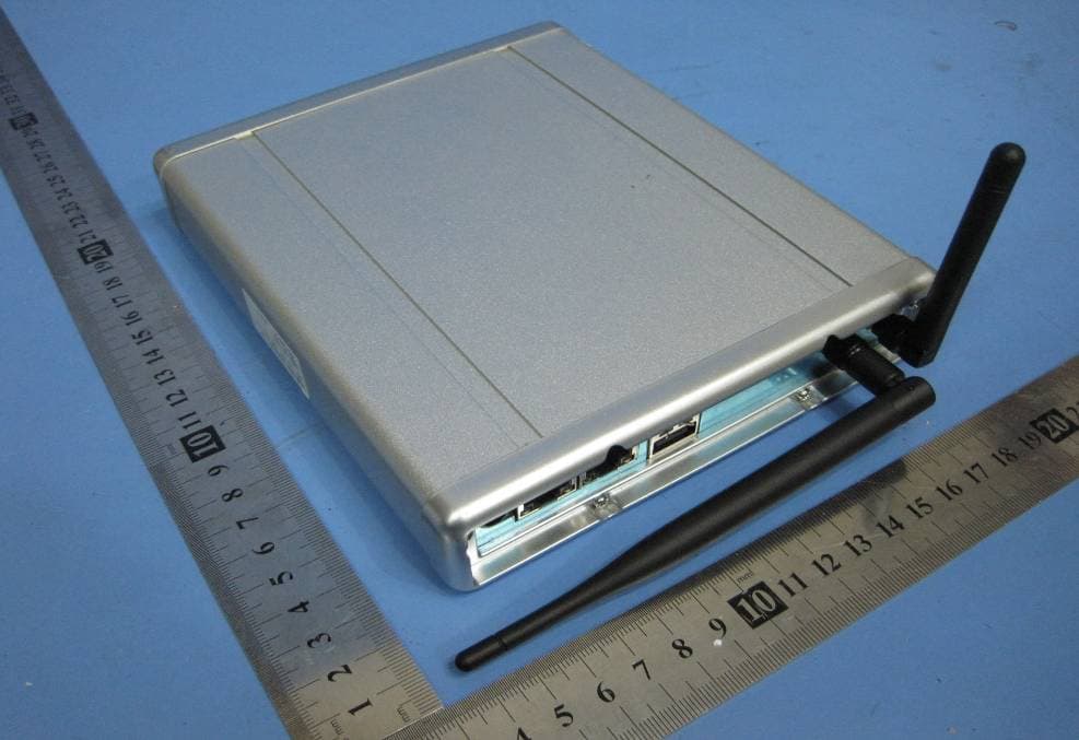
OU4-XG1000S-W
Jun 27, 2010WIFI GATEWAY
Equipment Class
DSC - Part 15 Security/Remote Control Transmitter
OU4-XCB80-FA
Feb 21, 2010FIRST ALERT BRIDGE
Equipment Class
DXX - Part 15 Low Power Communication Device Transmitter
OU4XPC260
Mar 21, 2007LAMP DIMMER
Equipment Class
DSC - Part 15 Security/Remote Control Transmitter
OU4XPC280
Mar 21, 2007GARAGE DOOR CONTROL
Equipment Class
DSC - Part 15 Security/Remote Control TransmitterOU4XG1000
Jul 12, 2006XANBOO REMOTE MONITORING AND ACCESS GATEWAY
Equipment Class
DSR - Part 15 Remote Control/Security Device Transceiver