OU4XBX300SUPERXAN II
Xanboo, Inc.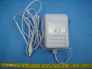
Click to zoom
Application Details
- Equipment Class
- DSC - Part 15 Security/Remote Control Transmitter
- Date of Grant
- Mar 31, 2005
- Application Purpose
- Original Equipment
- Date of Application
- Mar 31, 2005
- Equipment Note
- SUPERXAN II
- Frequency Range
- 418.00000000 - 418.20000000
- Company
- Xanboo, Inc.
- Country
- United States
Documents & Files
Document Text
Text extracted from the exhibit documents filed with the FCC. Open a document above to read the original.
Users Manual
Motorola homesight™ System Overview Congratulations on your purchase of the Motorola homesight Wireless System Controller. This guide describes how to set up and get started with homesight. The Motorola homesight system helps keep you informed day and night, rain or shine. The complete product line offers many advanced monitoring devices, including: 1. Wired and wireless video cameras 2. Wireless temperature sensors 3. Wireless water sensors 4. Wireless door/window sensors 5. Wireless Door/Window sensor 6. Siren You can manage your system on your home PC. With a broadband Internet connection, you can specify e-mail and cell phone, as either a text message or as text + image (depending on your provider), for delivery of notifications based on monitored events. For more information about Motorola homesight, go to http://www.motorola.com/homemonitoring/ To register your product, go to http://broadbandregistration.motorola.com Package Contents Computer System Requirements • PC with Intel Pentium®II or later processor, 2X CD-ROM drive, USB port, and 128 MB RAM running Windows Me®, Windows® 2000, or Windows XP™ for Home or Professional. • 45 MB of hard drive space recommended for installation; 500 MB (maximum) for archives . Installing the Software and Wireless System Controller Do not connect your Wireless System Controller to your computer until the Installation Wizard instructs you to do so. 1 Insert the enclosed Motorola homesight CD in the CD-ROM drive. The Motorola homesight Installation Wizard is displayed. a. If the application does not appear or autorun, right-click the Start button and select Explore. b. Select your CD-ROM and double-click to open. c. Double-click Launch.exe to start the application. Wireless System Controller Usb Connect Wire 12V Power Adapter homesight CD-ROM 2 Click Next. The Choose Destination Location window is displayed. 3 Click Next to accept the default destination folder or click Browse to select a new one. After you click Next, the Select Program Folder window is displayed. 4 Accept the default folder or choose a new one. Click Next. The file installation begins. After a few moments, the Install Motorola homesight Hardware and Driver window is displayed. 5 Plug the AC adapter into the Power port on the Wireless System Controller and into an AC wall outlet. This powers on your Wireless SysteController. Connect the USB cable on the Wireless System Controller to the USB port on, your Windows automatically installs required drivers. Once the driver installation is complete, click Next. The Software installation was successful, Windows display “Launch Motorola homesight” is selected. Click Finish. The Motorola Setup Wizard is display . If You Need Help If you encounter a problem setting up your homesight, try the following: 1 Verify that you followed the steps in the order specified. Be sure you plugged in all components to AC power. If necessary, try again. 2 Refer to your Motorola homesight device User Guides (printed or on CD-ROM) and the homesight Control Panel online help. 3 Check the http://www.motorola.com/homemonitoring/ website. 4 To request support seven days a week, 24 hours a day, go to: http://www.motorola.com/homemonitoring/support/ emailsupport.asp or call 1 (877) 466-8646. Wireless System Controller CAUTION: Changes or modifications not expressly approved by Motorola for compliance could void the user’s authority to operate the equipment. Regulatory Information FCC Compliance Class B Digital Device This equipment has been tested and found to comply with the limits for a Class B digital device, pursuant to Part 15 of the FCC Rules. These limits are designed to provide reasonable protection against harmful interference in a residential environment. This equipment generates, uses, and can radiate radio frequency energy and, if not installed and used in accordance with the instructions, may cause harmful interference to radio communications. However, there is no guarantee that interference will not occur in a particular installation. If this equipment does cause harmful interference to radio or television reception, which can be determined by turning the equipment off and on, the user is encouraged to try to correct the interference by one of the following measures: • Reorient or relocate the receiving antenna. • Increase the separation between the equipment and receiver. • Connect the equipment into an outlet on a circuit different from that to which the receiver is connected. • Consult the dealer or an experienced radio/TV technician for help. FCC Declaration of Conformity Motorola, Inc., Broadband Communications Sector, 101 Tournament Drive, Horsham, PA 19044, 1-215-323-1000, declares under sole responsibility that the HMVC3075 complies with 47 CFR Parts 2 and 15 of the FCC Rules as Class B digital devices. Industry Canada ICES-003 Statement This Class B digital apparatus complies with Canadian ICES-003. Cet appareil numérique de la classe B est conforme à la norme NMB-003 du Canada. Wireless LAN and Your Health This device, like other radio devices, emits radio frequency electromagnetic energy, but operates within the guidelines found in radio frequency safety standards and recommendations. Restrictions on Use of Wireless Devices In some situations or environments, the use of wireless devices may be restricted by the proprietor of the building or responsible representatives of the organization. If you are uncertain of the applicable policy for the use of wireless equipment in a specific organization or environment, you are encouraged to ask for authorization to use the device prior to turning on the equipment. The manufacturer is not responsible for any radio or television interference caused by unauthorized modification of the devices included with this product, or the substitution or attachment of connecting cables and equipment other than specified by the manufacturer. Correction of interference caused by such unauthorized modification, substi…
Text truncated - open the document above for the full version.
External Photos
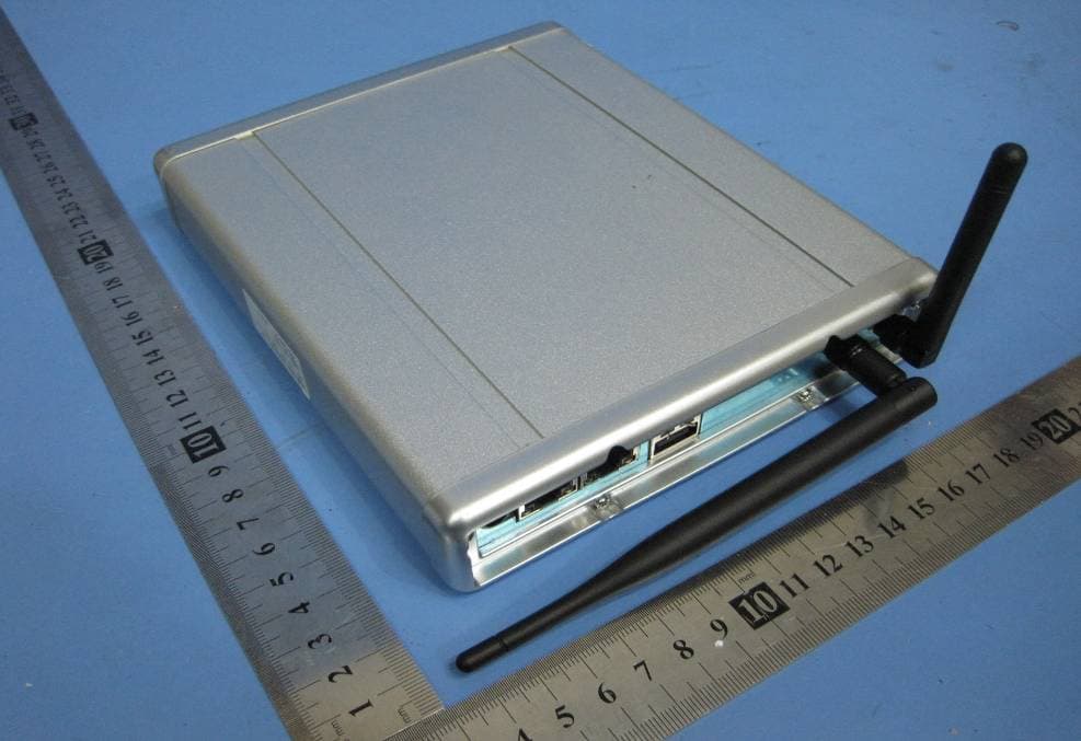
EUT – External Photos View 2.1 EUT - Front View 2.2 EUT - Back View 2.3 Adaptor - Front View 2.4 Adaptor - Back View
ID Label/Location Info
FCC ID Label Location This device complies with Part 15 of the FCC Rules. Operation is subject to the following two conditions:(1) this device may not cause harmful interference, and (2) this device must accpt any interference received, including interference that may cause undesired operation The Label must not be a stick-on paper. The Label on these products must be permanently affixed to the product and readily visible at the time of purchase and must last the expected lifetime of the equipment not be readily detachable. Proposed Label Location on EUT EUT Bottom View/proposed FCC Mark Location For Home or Offi ce Use
ID Label/Location Info
FCC ID Label Sample for Model XBX300 FCC ID: OU4XBX300 Made in China This device complies with Part 15 of the FCC Rules. Operation is subject to the following two conditions: 1. This device may not cause harmful interference, and 2. This device must accept any interference received, including interference that may cause undesired operation.
Internal Photos
2.1 PCB - Component View(1) 2.2 PCB - Component View (1.1) 2.3 PCB - PCB - Solder View(1) 2.4 PCB - Component View(2) 2.5 PCB - Solder View(2) 2.6 PCB - Component View(3) 2.7 PCB - Solder View(3)
Operational Description
XBX300 Feb, 16, 2005 Architecture XBX300 home monitoring & control system takes a sophisticated optimized 418MHz transceiver technology called “AFMII” protocol, and a Wi-Fi 2.4 GHz RX module to receive video and audio. It implements a proprietary wireless protocol that is similar in timing to the wired one. This allows for operation that appears transparent to standard AV signal. The hardware architecture is shown in Figure 1. 1 The home monitoring & control system is base on many advanced monitoring devices (including Wireless camera, Door sensors, Water sensors, Temperature sensors etc. For example Wireless camera provide a high quality video. And built-in heat-activated motion (PIR) detector, and an audio microphone. 2 Input +12V DC power into DC/DC circuit and from computer supply +5VDC created difference kinds of voltage support the Home monitoring & control system working. 3 The 2.4 GHz RX module is assigned to receiver the video, audio and PIR signal wirelessly. 4 The 418 MHz RF module is comprised of two chip, the transceiver chip CC1000, the baseband chip PIC16LF628 . The baseband chip is firmware the protocol, drive the transceiver chip to receive and transmit valid signal so that achieve all communication with Gateway or other device. 5 The MCU(PIC16F877 Micro controller unit deal with kinds of operation according to the Gateway through 418 MHZ RF radio module, including scan the discovery switch to initialize communication, detect the PIR trigger, flash the LED to indicate camera status, control switcher, and so on. 6 The Video Processing including MCU(PIC16C54 Micro controller unit deal with video control and indicate LED status ) and LM1881 Video Sync Separator processing. 7 Switcher control IC(HEF4052) control 3 wire Camera and 1 wireless Camera switch . 8 Digital processing unit Including Audio signal processing IC (MSM7716GS CODEC.) and Video signal processing IC (SAA7113 9-bit video processor) and USB data decoder IC (ZR36504 Full video and audio interface solution for video via USB) .
Schematics
18 XAN576 REV:1.1-02 S H E E T OF Superxan II DIMENSIONS ARE IN INCHES.TOLERANCES ARE= FRACTIONS=ANGULAR= DECIMALS= .XX .XXX SCALE: NONE APPROVALS DATE DRAWNCHECKEDAPPRV'DSIZE FILE B TITLE SUPERSEDESDRAWING NO. U N L E S S O T H E R W I S E S P E C I F I E D 115 West 30th Street 6th FL., New York, NY 10001 (646) 674 - 3000 R E V I S I O N S REV DESCRIPTION DATE APPR DR. BY NOTES: 1. ALL RESISTORS ARE IN OHMS.2. ALL CAPACITANCE IN FARADS. FRM-4, REV B (12/16/95) COMPUTER FILE # 1 2 3 4 ABCD ABCD ECO NO. 1 2 3 4 .02 1 DEGREE +-+- .025.005 +-+- THIS DOCUMENT AND THE DATA DISCLOSED HEREIN OR HEREWITH IS THE PROPERTY OF XANBOO AND IS NOT TO BE REPRODUCED, USED OR DISCLOSED IN WHOLE OR IN PART WITHOUT THE PERMISSION OF XANBOO. AL L PATENT, PROPRIETARY, DESIGN, USE, SALE, MANUFACTURING AND REPRODUCTION RIGHTS THERETO ARE RESERVED BY XANBOO. PRINT DATE 23-Dec-2004 08:41:25 TIME BOO 1.0 0709 PROTOTYPE 04-07-09 IV BB IVANM. GHALEBI COVER SHEET/POWER SUPPLY INT 04-12-2304-12-2304-12-23 B. BOLAM DO NOT INSTALL: 1 2 3 4 5 6 J7 M-DIN_6-R 1 2 3 4 5 6 J5 M-DIN_6-R 1 2 3 4 5 6 J8 M-DIN_6-R +12V_CAM_PWR5V_IN PWR_DWN_NT1004 +3.3V +3.3V_SW_NT1004 +5V_AFM2 +5V_VID_SWI POWERPOWER.S02 +5V_AFM2+3.3V_SW_NT1004+3.3V +12V_CAM_PWR PWR_DWN_NT1004 MAIN +3.3V_SW_NT1004+3.3VHSNCVSNCVCLKIICDTIICLKY[0:7]DAT_INFS_RBCLKCAPTRN D+ D- PWR_DWN_NT1004 DIGITALDIGITAL.S03 +3.3_SW_NT1004 HSNC VSNC VCLKIICDT IICLKY[0:7] CV_IN VIDEOVIDEO.S05 BCLK FS_R DAT_IN +3.3V_SW_NT1004AUD_IN_R AUDIOAUDIO.S04 DAT_INFS_RBCLK IICDTIICLK CV_IN VID_OUT AUD_OUT AUD_IN_R AB +5V_VID_SWI +12V_CAM_PWR A1A2A3A4V2V3V4V1 SWITCHERSWITCHER.S06 AB CAPTRN +3.3V_RX GND RF_BUSY RF_RX RF_DATA PIR1_INPIR2_INPIR3_IN RF_TX RF_RTSRF_CTS RSSI I2CLKI2CDT PIC16F874AFM2.S07 +5V_VID_SWI+12V_CAM_PWR C4368pF C4468pF C4568pF FB24 BK1608HM102FB23 BK1608HM102FB22 BK1608HM102 321 J6RSJ-353-103 FB14 BK1608HM102 FB15 BK1608HM102 C3568pF C3668pF AV OUT FB17 BK1608HM102FB19 BK1608HM102FB21 BK1608HM102FB13 BK1608HM102 FB12 BK1608HM102 FB16 BK1608HM102FB18 BK1608HM102FB20 BK1608HM102 C3268pFC3368pFC3468pFC3768pFC3868pFC3968pFC4068pFC4168pF + C91470uF C930.1uF +12V_CAM_PWR 321 J1 DC JACK FB4 BK1608HS600 R95 1R,1W 123456 J3 HOLE FOR CABLE FB5 BK1608HS600 FB6 BK1608HM102 FB7 BK1608HM102 R210R R220R R230R R240R R250R R19 10R R20 10R + C9410uF C3168pF D-D+ R261.5K PIR1_INPIR2_INPIR3_IN 1 TPG2 TP Y[0:7] +5V_VID_SWI A4V4 +5V_USB V4 A4 2.4GHz RX 2.4GHz RX.S08 +12V_CAM_PWR 1 2 D2 1N4004 AUD_OUTVID_OUT D-D+ A1A2A3A4-1V1V2V3V4-1 FB4, BK1608HM102 PAD4 R99R100R101 PAD1 PAD2 PAD3 +5V PAD5 PAD6 PAD7 +5V_IN PAD8 PAD14 PAD9 PAD10PAD11PAD12PAD13 PWR_DWN_HUBI2CDTI2CLK+5V_AFM2+12V_CAM_PWR I2CDTI2CLK DC_JACK GND-B DGND AGND EGND EGND EGND EGND EGND GND-A DGND AGND AGND AGNDAGNDAGNDAGNDAGNDAGNDAGNDAGND AGND AGND AGND EGND GND-C GND-C GND-C AGND R1180R R1190R GND-C GND-D EGND GND-C +3.3V_RXGND 1234567891011 P7 CON11 RF_TXE8(test point)RF_BUSYMCLR2RF_RXRF_DATARSSIRF_CTSRF_RTS 28 XAN576 REV:1.1-02 S H E E T OF Superxan II SIZE FILE B TITLE SUPERSEDESDRAWING NO. FRM-4, REV B (12/16/95) 1 2 3 4 ABCD ABCD 1 2 3 4 SEE SHEET 1 FOR NOTES AND APPROVALS PRINT DATE 23-Dec-2004 08:42:05 TIME 115 West 30th Street 6th FL., New York, NY 10001 (646) 674 - 3000 BOO + C89 220uF/16V + C90 220uF/35V THIS DOCUMENT AND THE DATA DISCLOSED HEREIN OR HEREWITH IS THE PROPERTY OF XANBOO AND IS NOT TO BE REPRODUCED, USED OR DISCLOSED IN WHOLE OR IN PART WITHOUT THE PERMISSION OF XANBOO. AL L PATENT, PROPRIETARY, DESIGN, USE, SALE, MANUFACTURING AND REPRODUCTION RIGHTS THERETO ARE RESERVED BY XANBOO. POWER DO NOT INSTALL: R3010K C520.1uF C530.1uF R29100K POWER VOUT 3 GND 2 VIN 1 GND 4 U4 LM2937IMP-3.3 +12V_CAM_PWR + C501uF C490.1uF + C4847uF C980.1uF +3.3V PWR_DWN_NT1004 Q1 SI2301DS +3.3V_SW_NT1004 SD G R1B1K LED6BLUE R2B68KR3B47K R4B10KR5B10K IO_1RC5 +5V_2.4GHz + C102100uF VOUT 1 SHDN 4 SENSE 2 GND 3 VIN 5 U12 LT1129CQ-5 C101 0.1uF R1020R R7BOR Q2SI2301DS SD G GND 2 VIN 1 VOUT 3 U13 78L05ACZ + C107100uF C108 0.1uF +5V_VID_SWI R6B 0R VOUT 3 GND 2 VIN 1 GND 4 U14 LM2937IMP-3.3 P12 P5 R103 0R R99 0R P1 P9 PWR_DWN_HUB + C109100uF C110 0.1uF +3.3V_RX +5V +5V_IN +5V_AFM2 1 3 2 12 J14CON2 EGND EGND EGNDEGND EGND EGND AGND AGND AGND GND-C GND-D GND-D GND-D GND-D GND-D GND-C GND-C GND-C GND-C GND-C +12V_CAM_PWR 38 XAN576 REV:1.1-02 S H E E T OF Superxan II SIZE FILE B TITLE SUPERSEDESDRAWING NO. FRM-4, REV B (12/16/95) 1 2 3 4 ABCD ABCD 1 2 3 4 SEE SHEET 1 FOR NOTES AND APPROVALS PRINT DATE 23-Dec-2004 08:42:20 TIME 115 West 30th Street 6th FL., New York, NY 10001 (646) 674 - 3000 BOO + C60 0.1uF C58 22PF C620.1uF THIS DOCUMENT AND THE DATA DISCLOSED HEREIN OR HEREWITH IS THE PROPERTY OF XANBOO AND IS NOT TO BE REPRODUCED, USED OR DISCLOSED IN WHOLE OR IN PART WITHOUT THE PERMISSION OF XANBOO. AL L PATENT, PROPRIETARY, DESIGN, USE, SALE, MANUFACTURING AND REPRODUCTION RIGHTS THERETO ARE RESERVED BY XANBOO. DIGITAL DO NOT INSTALL: R6047K R450R R38100K C6547pF C611uF FB27 BK1608HM102 +3.3V R4110K DIGITAL AGND 1 Y0 2 VDD 3 DGND 4 Y1 5 Y2 6 Y3 7 Y4 8 Y5 9 Y6 10 Y7 11 U0 12 U1 13 U2 14 DGND 15 U3 16 U4 17 U5 18 U6 19 U7 20 V0 21 V1 22 V2 23 V3 24 V4 25 V5 26 V6 27 VDD 28 V7 29 TEST1(MST) 30 VCLK 31 HVALID 32 VSNC 33 HSNC 34 FID 35 AGND 36 VDDA 37 IO_1 38 IO_2 39 DGND 40 XIN 41 VDDA 42 XOUT 43 BLK_FULL 44 BLK_EN 45 DAT_IN 46 FS_L 47 FS_R 48 BCLK 49 CLK48 50 DD0 51 DD15 52 VDD 53 DGND 54 DD1 55 DD14 56 DD2 57 DD13 58 DD3 59 DD12 60 DD4 61 DD11 62 DD5 63 DD10 64 DGND 65 DD6 66 DD9 67 DD7 68 DD8 69 CASN 70 WRN 71 OEN 72 RASN 73 DA0 74 DA1 75 DA2 76 DA3 77 VDD 78 DGND 79 DA4 80 DA5 81 DA6 82 DA7 83 DA8 84 DA9 85 SCL/PWR0 86 SDA/EEPROM 87 PWR1 88 RESIN 89 DGND 90 SENS 91 IICDT 92 IICCK 93 PWR_DWN 94 SUSPND 95 CAPTRN 96 TEST2(VPD) 97 VDDA 98 USB_VP 99 USB_VM 100 U7 NT1004 VCC 1 DQ1 2 DQ2 3 DQ3 4 DQ4 5 VCC 6 DQ5 7 DQ6 8 DQ7 9 DQ8 10 NC 13 NC 14 WE 15 RAS 16 NC 17 A0 18 A1 19 A2 20 A3 21 VCC 22 VSS 23 A4 24 A5 25 A6 26 A7 27 A8 28 OE 29 UCAS 30 LCAS 31 NC 32 DQ9 35 DQ10 36 DQ11 37 DQ12 38 VSS 39 DQ13 40 DQ14 41 DQ15 42 DQ16 43 VSS 44 U6GLT440L16-40TC R6347K…
Text truncated - open the document above for the full version.
Test Report
FCC TEST REPORT FCC ID : OU4XBX300 Applicant : Xanboo Inc 115 WEST 30 TH STREET,6 TH FLOOR NEW YORK, NY10001 Equipment Under Test (EUT) : Product description : Superxan II Model No. : XBX300 Standards : FCC 15 Paragraph 15.205, Paragraph 15.209, Paragraph 15.231, Paragraph 15.31, Paragraph 15.33, Paragraph 15.35. Date of Test : March 28, 2005 Test Engineer : Peter Lin Reviewed By : PERPARED BY: Shenzhen Academy Of Metrology and Quality Inspection EMC Laboratory Bldg, of Metrology and Quality Inspection ,Longzhu Road ,Nanshan District ,Shenzhen ,Guangdong ,China FCC Registration Number: 97379 Industry Canada Registration Number: IC4174 Page 1 of 33 Xanboo Inc FCC ID:OU4XBX300 2 Contents Page 1 COVER PAGE..........................................................................................................................................................1 2 CONTENTS..............................................................................................................................................................2 3 TEST SUMMARY....................................................................................................................................................5 4 GENERAL INFORMATION..................................................................................................................................6 4.1 CLIENT INFORMATION............................................................................................................................................6 4.2 GENERAL DESCRIPTION OF E.U.T...........................................................................................................................6 4.3 DETAILS OF E.U.T..................................................................................................................................................6 4.4 DESCRIPTION OF SUPPORT UNITS...........................................................................................................................6 4.5 STANDARDS APPLICABLE FOR TESTING..................................................................................................................6 4.6 TEST FACILITY........................................................................................................................................................7 4.7 TEST LOCATION......................................................................................................................................................7 5 EQUIPMENT USED DURING TEST...................................................................................................................8 6 CONDUCTED EMISSION TEST..........................................................................................................................9 6.1 TEST EQUIPMENT....................................................................................................................................................9 6.2 TEST PROCEDURE...................................................................................................................................................9 6.3 CONDUCTED TEST SETUP.....................................................................................................................................10 6.4 EUT OPERATING CONDITION...............................................................................................................................10 6.5 CONDUCTED EMISSION LIMITS.............................................................................................................................11 6.6 CONDUCTED EMISSION TEST DATA......................................................................................................................12 6.7 CONDUCTIED EMISSIONS TEST DATA...................................................................................................................14 7 RADIATION EMISSION TEST...........................................................................................................................15 7.1 TEST EQUIPMENT..................................................................................................................................................15 7.2 MEASUREMENT UNCERTAINTY.............................................................................................................................15 7.3 TEST PROCEDURE.................................................................................................................................................15 7.4 RADIATED TEST SETUP.........................................................................................................................................16 7.5 SPECTRUM ANALYZER SETUP...............................................................................................................................16 7.6 CORRECTED AMPLITUDE & MARGIN CALCULATION............................................................................................17 7.7 SUMMARY OF TEST RESULTS................................................................................................................................17 7.8 EUT OPERATING CONDITION...............................................................................................................................18 7.9 RADIATED EMISSIONS LIMIT.................................................................................................................................18 7.10 RADIATED EMISSIONS TEST RESULT................................................................................................................20 8 PERIODIC OPERATION.....................................................................................................................................22 9 BAND EDGE..........................................................................................................................................................23 9.1 TEST PROCEDURE..................................…
Text truncated - open the document above for the full version.
Test Setup Photos
Test Setup Photos 1. Conduction Emission Test Setup 2. Radiation Emission Test setup 2.1 Radiation Emission Test View For 30MHz-1000MHz 2.2 Radiation Emission Test View For 1GHz-5GHz
Contact Information
Applicant
Kent E Britain(Sr. RF Engineer)
Test Firm
Shenzhen Academy of Metrology & Quality InspectionPeter Lin
Technical Specifications
| # | Rule Parts | Frequency Range | Power Output |
|---|---|---|---|
| 1 | 15.231 | 418 MHz - 418.2 MHz | - |
Other Applications from Xanboo, Inc.
OU4-XG1000S-W
Jun 27, 2010WIFI GATEWAY
Equipment Class
DSC - Part 15 Security/Remote Control Transmitter
OU4-XCB80-FA
Feb 21, 2010FIRST ALERT BRIDGE
Equipment Class
DXX - Part 15 Low Power Communication Device Transmitter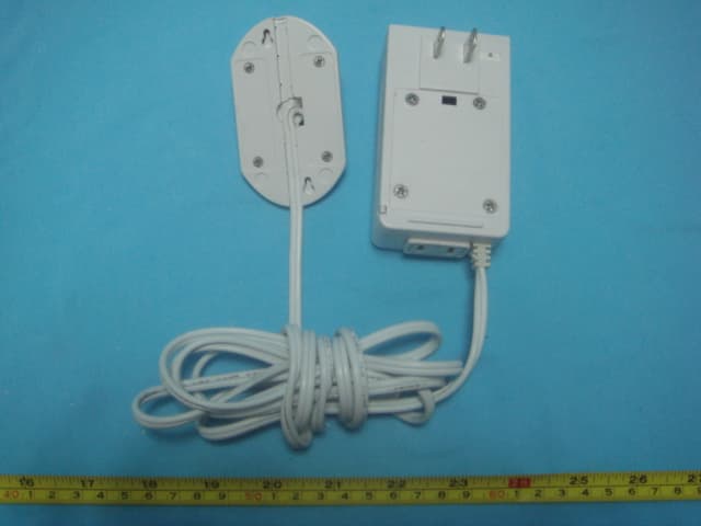
OU4XPC260
Mar 21, 2007LAMP DIMMER
Equipment Class
DSC - Part 15 Security/Remote Control Transmitter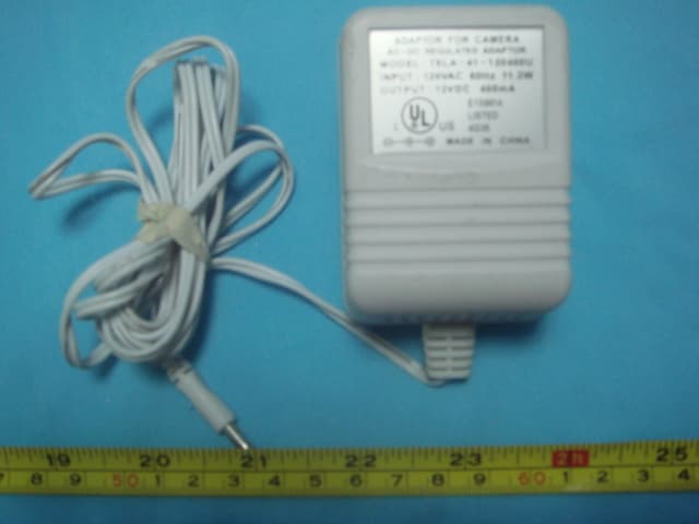
OU4XPC280
Mar 21, 2007GARAGE DOOR CONTROL
Equipment Class
DSC - Part 15 Security/Remote Control TransmitterOU4XG1000
Jul 12, 2006XANBOO REMOTE MONITORING AND ACCESS GATEWAY
Equipment Class
DSR - Part 15 Remote Control/Security Device Transceiver