OU4XWC900-HRDNCCD DAY/NIGHT MCAM-TX
Xanboo, Inc.
Click to zoom
Application Details
- Equipment Class
- DXX - Part 15 Low Power Communication Device Transmitter
- Date of Grant
- Mar 22, 2005
- Application Purpose
- Original Equipment
- Date of Application
- Mar 22, 2005
- Equipment Note
- CCD DAY/NIGHT MCAM-TX
- Frequency Range
- 2410.00000000 - 2470.00000000
- Company
- Xanboo, Inc.
- Country
- United States
Documents & Files
Document Text
Text extracted from the exhibit documents filed with the FCC. Open a document above to read the original.
Users Manual
Instruction Product description /// Congratulations on your purchase of the Motorola Wireless Camera. Your camera uses a high-resolution color video camera, a built-in heat-activated motion detector, and an audio microphone. These features enable you to secure an area, regardless of day or night, rain or shine. This Quick Start Guide describes how to set up and troubleshoot your Wireless Camera. Controlling Your Camera Using your computer and the Gateway, you locally manage your home environment with the Motorola Home Monitoring & Control System. When configured, the system can notify you of any new events by sending an e-mail when your Wireless Camera detects an event. An event is defined as movement in the field of view of the camera heat sensor. How It Works The Wireless Camera surveys the area up to 18-28 ft. (5-8m) at a viewing angle of 80 degrees. If armed, heat-motion triggers the camera and the camera and turns it on automatically and begins transmitting the image. The camera then communicates the video wirelessly back to the Gateway, which in turn feeds your computer. This enables you to watch the video to determine the events\ that triggered it. Installation Overview Your package contains the following: The Gateway must be installed before activating you camera! Installing you camera is a simple two-step process. 1 Register your camera with your Gateway using a process called discovery. Refer to your Gateway documentation for instructions on how to discover your Wireless Camera. 2 Mount the camera. Installation hints The Motorola Wireless Camera is constructed of UV resistant ABS plastic. Please consider the following points when mounting the camera --- The camera must be aimed so that it does not directly face the sun or any bright light, otherwise, this may cause damage to the camera. --- Avoid viewing areas where half of the area is in bright sunlight and the other half is dark. All types of cameras have difficulty seeing wide variations of light. --- If installing the Wireless Camera outside, it should be shielded from the elements, such as underneath a porch. Do not install the camera where it is subjected directly to the elements. --- Typically, the camera’s wireless reception is good up to 60-80 feet depending on the number of obstacles. These can include metal framing, thick walls, and other wireless devices operating at 2.4 GHz. It is recommended that different positions as well as varying antenna adjustments be tried. Installing Your Camera Your camera can either be mounted on a wall or just sit on a level surface. Wall Mount Your Wireless Camera Make sure the power adapter cord is long enough to reach your mounting location. Also, be sure the AC outlet cannot be switched on and of with a wall-switch. Warning, when mounting near a window, drilling too close to the glass could break the glass and possibly cause it to shatter. The window extends deeper into the frame than can be seen; therefore, ensure your screw is beyond the glass before drilling. 1 Using the holes on the drilling template found later in this guide, mark the position of the Hole to be drilled. For drywall of other composite surfaces use a 7/32” drill bit, Drill a hole for each of the mounting screws and insert a plastic wall anchor into each hole. For other solid surfaces, use a 1/16” drill bit. Drill a pilot hole for each of the mounting screws. 2 Using the screws provided, secure the camera to the wall When mounting the screws to the Wall, leave 1/16” (1/6 mm) space between head and the wall. Using the mounting, slide the camera down on to the screws until it is firmly seated. 3 Position the camera to view the desired area and plug in the power supply. Please keep in Mind that the field of view is 80 degrees and motion sensor distance works up to 18-28 ft. (5-8 m). 4 Make slight adjustments to the camera-viewing angle by tilting and panning the camera head by hand. 5 It is recommended that the antenna be set vertically. Tabletop Mount Your Wireless Camera The camera can be placed on any level surface. 1 Plug the power supply into camera and then to the wall. 2 Make adjustments to the camera viewing angle by tilting and panning the camera head with your hand. 3 Adjust the antenna as needed. It is recommended that the antenna stay at a 90-degree angle to the base of the camera for the best wireless reception. Troubleshooting Problem solution Camera will Ensure the camera is powered. Not register Ensure that the Gateway is powered and online. With the Ensure you are pressing the Discovery button. Gateway Reposition the camera closer to the Gateway. No camera Ensure the camera is powered . Picture Ensure that the Gateway is powered and online. Ensure you have the proper camera selected. Reposition the camera closer to the Gateway. Reposition the antenna. Poor Picture Ensure that you are suing the proper power supply. Quality Make sure proper camera quality setting are configured when viewing. Make sure your camera viewing area has proper lighting Try another location Adjust the camera antenna Select other operating channels on other 2.4 GHz devices Motion events Ensure the camera is not positioned behind glass. Are not triggered The notion sensor is triggered by changes in heat. Any material such as glass that “insulates” keeps the camera form Detecting heat changes (movement) Ensure the camera head is positioned properly. Audio problems Make sure your volume is turned up when playing back the video clip. Make sure the sound is within the microphone range (6-10 feet) Does the computer have a sound card and are the speakers activated And loud enough? Features and Specification PIR motion detection LED in camera illuminates when activity occurs Microphone captures audio 80 degree field of view for motion and camera lens Weather resistant Auto Brightness, Auto Contrast, Auto White-Balance All hardware for wither wall of ceiling mounting included AC power supply Image sensor: 1/4-inch color …
Text truncated - open the document above for the full version.
External Photos
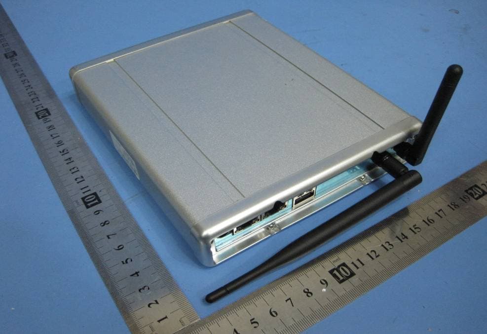
EUT – External Photos View 2.1 EUT - Front View 2.2 EUT - Back View 2.3 Adaptor - Front View 2.4 Adaptor - Back View
ID Label/Location Info
FCC ID Label Location This device complies with Part 15 of the FCC Rules. Operation is subject to the following two conditions:(1) this device may not cause harmful interference, and (2) this device must accpt any interference received, including interference that may cause undesired operation The Label must not be a stick-on paper. The Label on these products must be permanently affixed to the product and readily visible at the time of purchase and must last the expected lifetime of the equipment not be readily detachable. Proposed Label Location on EUT EUT Bottom View/proposed FCC Mark Location For Home or Offi ce Use
ID Label/Location Info
FCC ID Label Sample for Model XWC900-HRDN FCC ID: OU4XWC900-HRDN Made in China This device complies with Part 15 of the FCC Rules. Operation is subject to the following two conditions: 1. This device may not cause harmful interference, and 2. This device must accept any interference received, including interference that may cause undesired operation.
Internal Photos
2.1 PCB - Component View(1) 2.2 PCB - Component View (1.1) 2.3 PCB - PCB - Solder View(1) 2.4 PCB - Component View(2) 2.5 PCB - Solder View(2) 2.6 PCB - Component View(3) 2.7 PCB - Solder View(3) 2.8 PCB - Component View(4) 2.9 PCB - Solder View(4) 2.10 PCB - Component View(5) 2.11 PCB - Solder View(5) 2.12 PCB - Component View(6) 2.13 PCB - Solder View(6) 2.14 PCB - Component View(7) 2.15 PCB - Solder View(7)
Operational Description
XWC900-HRDN Jan 22, 2005 Architecture XWC900-HRDN wireless camera takes a sophisticated optimized 418MHz transceiver technology called “AFMII” protocol, and a Wi-Fi 2.4 GHz TX module to transmit video and audio. It implements a proprietary wireless protocol that is similar in timing to the wired one. This allows for operation that appears transparent to standard AV signal. The hardware architecture is shown in Figure 1. 1 The camera is base on a CCD color camera sensor to provide a high quality video. a built-in heat-activated motion (PIR) detector, and an audio microphone. 2 Input +12V DC power into DC/DC circuit, created difference kinds of voltage support the camera working. 3 The 2.4 GHz TX module is assigned to transmit the video, audio and PIR signal wirelessly. 4 The 418 MHz RF module is comprised of two chip, the transceiver chip CC1000, the baseband chip PIC16LF628 . The baseband chip is firmware the protocol, drive the transceiver chip to receive and transmit valid signal so that achieve all communication with Gateway or other device. 5 The MCU (Micro controller unit) deal with kinds of operation according to the Gateway through 418 MHZ RF radio module, including scan the discovery switch to initialize communication, detect the PIR trigger, flash the LED to indicate camera status, and so on.
Schematics
S H E E T OF SIZE FILE B TITLE SUPERSEDESDRAWING NO. 1 2 3 4 ABCD ABCD 1 2 3 4 SEE SHEET 1 FOR NOTES AND APPROVALS PRINT DATE TIME 115 West 30th Street 6th FL., New York, NY 10001 (646) 674 - 3000 BOO THIS DOCUMENT AND THE DATA DISCLOSED HEREIN OR HEREWITH IS THE PROPERTY OF XANBOO AND IS NOT TO BE REPRODUCED, USED OR DISCLOSED IN WHOLE OR IN PART WITHOUT THE PERMISSION OF XANBOO. AL L PATENT, PROPRIETARY, DESIGN, USE, SALE, MANUFACTURING AND REPRODUCTION RIGHTS THERETO ARE RESERVED BY XANBOO. 12 XAN0408 Rev1.4-02 XAN0408_1_4 2004-01-14 10:07:24 CC1000 AGND 2 RF_IN 3 RF_OUT 4 AVDD 5 AGND 6 AGND 7 AVDD 9 L1 10 AVDD 1 DGND 20 DVDD 21 DGND 22 DIO 23 DCLK 24 PCLK 25 PDATA 26 PALE 27 RSSI/IF 28 L2 11 CHP_OUT 12 R_BIAS 13 AGND 14 AVDD 15 AGND 16 XOSC_Q2 17 XOSC_Q1 18 AGND 8 AGND 19 U1 CC1000 XL4 33nH, 5% +3.3V R131 82k +3.3V XX1 11.0592 Mhz C141 16pF C15116pF C15 1nF C2220pF C14 220pF C13 220pF C12 1nF C11 1nF C10 33nF XL268nH XL36.2nH XC5 8.2pF +3.3V XC3 15pF XC4 5.6pF L2BLM11A102S RSSI R1TBA C4TBA XL1 8.2nH XC122pF XC215pF LOW PASS FILTER NOT FITTED C3TBA 433MHz XAN0408_1_4 TKS2351CT-ND PALEPDATAPCLKDCLKDIO C131 4.7pF + C13.3uF C1733nF ANT S H E E T OF SIZE FILE B TITLE SUPERSEDESDRAWING NO. 1 2 3 4 ABCD ABCD 1 2 3 4 SEE SHEET 1 FOR NOTES AND APPROVALS PRINT DATE TIME 115 West 30th Street 6th FL., New York, NY 10001 (646) 674 - 3000 BOO THIS DOCUMENT AND THE DATA DISCLOSED HEREIN OR HEREWITH IS THE PROPERTY OF XANBOO AND IS NOT TO BE REPRODUCED, USED OR DISCLOSED IN WHOLE OR IN PART WITHOUT THE PERMISSION OF XANBOO. AL L PATENT, PROPRIETARY, DESIGN, USE, SALE, MANUFACTURING AND REPRODUCTION RIGHTS THERETO ARE RESERVED BY XANBOO. 22 XAN0408 Rev1.4-02 XAN0408_1_4 2004-01-14 10:06:51 MICROCONTROLLER C5 0.1uF Y1 4Mhz C6 33pF C7 33pF PIC_VCC RF_DATARF_BUSYRF_RXRF_TX R24.7K R4000 R31K LED1GREEN RF_RTSRF_CTS +3.3V MCLR2DIAG PIC_VCC RA2/AN2/Vref 1 RA3/AN3/CMP1 2 RA4/TOCKI/CMP2 3 RA5/MCLR/THV 4 Vss 5 RB0/INT 7 RB1/RX/DT 8 RB2/TX/CK 9 RB3/CCP1 10 RB4/PGM 11 RB5 12 RB6/T1OSO/T1CKI 13 RB7/T1OSI 14 VDD 15 RA6/OSC2/CLKOUT 17 RA7/OSC1/CLKIN 18 RA0/AN0 19 RA1/AN1 20 Vss 6 VDD 16 U2PIC16LF628 XAN0408_1_4 R5100k PIC_VCC D1 DIO5711WS MCLR2 VPP 1234567891011 P1CON11 RSSI DCLKPDATAPCLKPALEDIO RF_RXRF_TXDIAGRF_BUSYRF_DATARF_RTSRF_CTS 13 XAN507 S H E E T OF MCAM DIMENSIONS ARE IN INCHES.TOLERANCES ARE= FRACTIONS=ANGULAR= DECIMALS= .XX .XXX SCALE: NONE APPROVALS DATE DRAWN:CHECKED:APPRV'D: SIZE FILE B TITLE MODEL NO:PCB NO: U N L E S S O T H E R W I S E S P E C I F I E D 115 West 30th Street 6th FL., New York, NY 10001 (646) 674 - 3000 R E V I S I O N S REV DESCRIPTION DATE APPR DR. BY NOTES: 1. ALL RESISTORS ARE IN OHMS.2. ALL CAPACITANCE IN FARADS. FRM-4, REV B (12/16/95) COMPUTER FILE # ABCD ABCD ECO NO. 1 2 3 4 .02 1 DEGREE +-+- .025.005 +-+- THIS DOCUMENT AND THE DATA DISCLOSED HEREIN OR HEREWITH IS THE PROPERTY OF XANBOO AND IS NOT TO BE REPRODUCED, USED OR DISCLOSED IN WHOLE OR IN PART WITHOUT THE PERMISSION OF XANBOO. AL L PATENT, PROPRIETARY, DESIGN, USE, SALE, MANUFACTURING AND REPRODUCTION RIGHTS THERETO ARE RESERVED BY XANBOO. PRINT DATE 28-Dec-2004 17:37:32 TIME BOO Inc SHEETS INFORMATION SHEET 1SHEET 2SHEET 3SHEET 4 COVER SHEET/POWER SUPPLY INTERNAL SHEET FUNCTION SHEET 5 1.00 0927 PROTOTYPE 09/27/02 OV BB SHEET 6SHEET 7SHEET 8 COVER SHEET/POWER SUPPLY INT SHEET 10SHEET 9SHEET 11 COMPANY: REV:REV: + C1100uF C2.1uF GND 2 VOUT 3 VIN 1 U4 LT1121CST-3.3 C9 .1uF + C2110uF +3.3V +5V + C43100uF C46 .1uF C47 .1uF + C4810uF GND 2 VOUT 3 VIN 1 U5LM2937IMP-5 VID PROTOCOL CONTROL2.4GHz TX 1.4-02 Bruce VID Protocol controlVID Protocol control22.4G TX R40000 R41000R42000 PIR_VCC PIC_VCC PIC_VCCPIR_VCC R39000 + C22470uF Do Not Install CAM_POWER CAM_ENABLE TX_POWER TX_ENABLE + C252.2uF + C262.2uF Q2SI2301DSQ3SI2301DS R6947kR7047k +5V R7122k 3 1 2 Q6BC847AL 3 1 2 Q7 BC847AL R7222k +5V+5V R744.7K R734.7K C8.1uFC49.1uF + C27470uF R3000 R2000 +3.3V +VE AC LM2937IMP-3.3 XAN507 1.4 2004-12-23 +VEAC SPAREGND R3,R39,R40 23 XAN507 S H E E T OF MCAM SIZE FILE B TITLE MODEL NO:PCB NO: FRM-4, REV B (12/16/95) 1 2 3 4 ABCD ABCD 1 2 3 4 SEE SHEET 1 FOR NOTES AND APPROVALS PRINT DATE 2004-12-23 17:38:00 TIME 115 West 30th Street 6th FL., New York, NY 10001 (646) 674 - 3000 BOO THIS DOCUMENT AND THE DATA DISCLOSED HEREIN OR HEREWITH IS THE PROPERTY OF XANBOO AND IS NOT TO BE REPRODUCED, USED OR DISCLOSED IN WHOLE OR IN PART WITHOUT THE PERMISSION OF XANBOO. AL L PATENT, PROPRIETARY, DESIGN, USE, SALE, MANUFACTURING AND REPRODUCTION RIGHTS THERETO ARE RESERVED BY XANBOO. VID PROTOCOL CONTROL REV:REV: R16 150 R15 150 RG 1 2 3 LED2LED, TRI COLOR C17.1uF MCLR/Vpp 2 RA0/AN0 3 RA1/AN1 4 RA2/AN2/Vref- 5 RA3/AN3/Vref+ 6 RA4/T0CKI 7 RA5/AN4/SS 8 RE0/RD/AN5 9 RE1/WR/AN6 10 RE2/CS/AN7 11 VDD 12 VSS 13 OSC1/CLKIN 14 OSC2/CLKOUT 15 RC0/T1OSI/T1CKI 16 RC1/T1OSI/CCP2 18 RC2/CCP1 19 RC3/SCK/SCL 20 RD0/PSP0 21 RD1/PSP1 22 RD2/PSP2 23 RD3/PSP3 24 RC4/SDI/SDA 25 RC5/SDO 26 RC6/TX/CK 27 RC7/RX/DT 29 RD4/PSP4 30 RD5/PSP5 31 RD6/PSP6 32 RD7/PSP7 33 VSS 34 VDD 35 RB0/INT 36 RB1 37 RB2 38 RB3/PGM 39 RB4 41 RB5 42 RB6/PGC 43 RB7/PGD 44 NC 1 NC 17 NC 28 NC 40 U6 * PIC_VCC Y2 10MHz PIC_VCC D4 1N5817 RD2RD3 R2310k R2810k R2710k PIC_VCC PIC_VCC PIC_VCC KEYFOB INTERFACE PROGRAM RF_RTSRF_CTS R13100k R11100k R1010k R32100k R31100k R3310k +3.3V RF_RXRF_TXRF_BUSYRF_DATA C18.1uF 3 1 2 Q1BC847AL R25 1k SP1 +VE R26100k BAT_LOW PIR AC_DC R2410k PIC_VCC C2018pF C1918pF 12345678 P1 HDR4X2 PLL_CHIP_LEPLL_CHIP_DATAPLL_CHIP_CLOCK R211M R2010k AC D5 1 3 SW1 KTS1101Y R30 4.7k RB1 R12 470 R14 470 R17 470 R18 4.7K R22 470 R19 470 TX_ENABLECAM_ENABLE RA4 RA4 RA5 RA5RA2 RA2VLED+3.3V RED GREEN RC5 12345678 J8 MCLR RF_RTSRF_CTSRF_BUSY+3.3V R34 10k R35 10K VLED R36 10k R37100k R38100k TP1 TP2TP3 TP4 TP5 TP6 DO NOT INSTALL: LED2 12345 J2 5PINHEADER RC4 RC3 PIC_VCC R6100k R7100k RC3RC4 D7 * PIC_VCC C15,C16 1N5711SW PIC16F874 MCLR2 1.4-02 R33,10K R291M PIC_VCC 23 1 T1 +VE BAT_LOW R6130K R62 24K TC54VN3002ECB R80470 R510k 3 1 2 Q8BC847AL R44.7K MCLR2 RC2 1234567891011 J1CON11 RF_RTSRF_CT…
Text truncated - open the document above for the full version.
Test Report
FCC TEST REPORT FCC ID : OU4XWC900-HRDN Applicant : Xanboo Inc 115 WEST 30 TH STREET,6 TH FLOOR NEW YORK, NY10001 Equipment Under Test (EUT) : Product description : CCD Day/Night MCAM Model No. : XWC900-HRDN Standards : FCC 15 Paragraph 15.205, Paragraph 15.209, Paragraph 15.231, Paragraph 15.249,Paragraph 15.31, Paragraph 15.33, Paragraph 15.35. Date of Test : March 09, 2005 Test Engineer : Jimmy Lee Reviewed By : PERPARED BY: Shenzhen Huatongwei International Inspection Co., Ltd Keji S,12th,Road, Hi-tech Industrial Park, Shenzhen, Guangdong, China FCC Registration Number: 662850 Page 1 of 38 Xanboo Inc FCC ID:OU4XWC900-HRDN 2 Contents Page 1 COVER PAGE..........................................................................................................................................................1 2 CONTENTS..............................................................................................................................................................2 3 TEST SUMMARY....................................................................................................................................................5 4 GENERAL INFORMATION..................................................................................................................................6 4.1 CLIENT INFORMATION............................................................................................................................................6 4.2 GENERAL DESCRIPTION OF E.U.T...........................................................................................................................6 4.3 DETAILS OF E.U.T..................................................................................................................................................6 4.4 DESCRIPTION OF SUPPORT UNITS...........................................................................................................................6 4.5 STANDARDS APPLICABLE FOR TESTING..................................................................................................................6 4.6 TEST FACILITY........................................................................................................................................................7 4.7 TEST LOCATION......................................................................................................................................................7 5 EQUIPMENT USED DURING TEST...................................................................................................................8 6 CONDUCTED EMISSION TEST..........................................................................................................................9 6.1 TEST EQUIPMENT....................................................................................................................................................9 6.2 TEST PROCEDURE...................................................................................................................................................9 6.3 CONDUCTED TEST SETUP.....................................................................................................................................10 6.4 EUT OPERATING CONDITION...............................................................................................................................10 6.5 CONDUCTED EMISSION LIMITS.............................................................................................................................11 6.6 CONDUCTED EMISSION TEST DATA......................................................................................................................12 6.7 CONDUCTIED EMISSIONS TEST DATA...................................................................................................................13 7 RADIATION EMISSION TEST...........................................................................................................................14 7.1 TEST EQUIPMENT..................................................................................................................................................14 7.2 MEASUREMENT UNCERTAINTY.............................................................................................................................14 7.3 TEST PROCEDURE.................................................................................................................................................14 7.4 RADIATED TEST SETUP.........................................................................................................................................15 7.5 SPECTRUM ANALYZER SETUP...............................................................................................................................15 7.6 CORRECTED AMPLITUDE & MARGIN CALCULATION............................................................................................16 7.7 SUMMARY OF TEST RESULTS................................................................................................................................16 7.8 EUT OPERATING CONDITION...............................................................................................................................17 7.9 RADIATED EMISSIONS LIMIT.................................................................................................................................17 7.10 RADIATED EMISSIONS TEST RESULT................................................................................................................19 8 PERIODIC OPERATION.....................................................................................................................................22 9 BAND EDGE..........................................................................................................................................................23 9.1 TEST PROCEDURE....................................................................................…
Text truncated - open the document above for the full version.
Test Setup Photos
Test Setup Photos 1. Conduction Emission Test Setup 2. Radiation Emission Test setup 2.1 Radiation Emission Test View For 30MHz-1000MHz 2.2 Radiation Emission Test View For 1GHz-25GHz
Contact Information
Applicant
Kent E Britain(Sr. RF Engineer)
Test Firm
Shenzhen Huatongwei International Insp. Co., LtdMoffy Yu
Technical Specifications
| # | Rule Parts | Frequency Range | Power Output |
|---|---|---|---|
| 1 | 15C | 2.41 GHz - 2.47 GHz | - |
Other Applications from Xanboo, Inc.
OU4-XG1000S-W
Jun 27, 2010WIFI GATEWAY
Equipment Class
DSC - Part 15 Security/Remote Control Transmitter
OU4-XCB80-FA
Feb 21, 2010FIRST ALERT BRIDGE
Equipment Class
DXX - Part 15 Low Power Communication Device Transmitter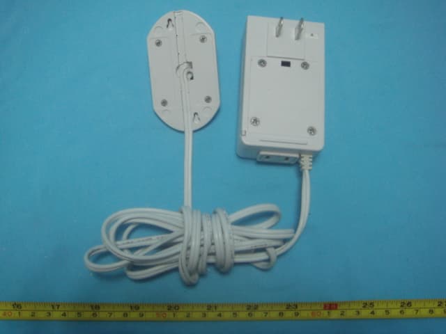
OU4XPC260
Mar 21, 2007LAMP DIMMER
Equipment Class
DSC - Part 15 Security/Remote Control Transmitter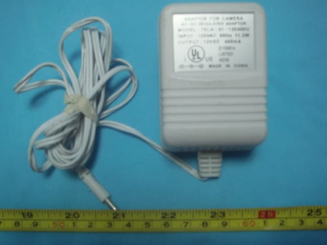
OU4XPC280
Mar 21, 2007GARAGE DOOR CONTROL
Equipment Class
DSC - Part 15 Security/Remote Control TransmitterOU4XG1000
Jul 12, 2006XANBOO REMOTE MONITORING AND ACCESS GATEWAY
Equipment Class
DSR - Part 15 Remote Control/Security Device Transceiver