OUR-9XTEND9XTEND OEM RF Module
MaxStream Inc.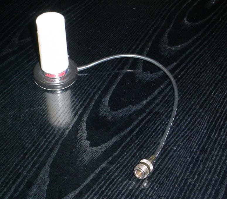
Click to zoom
Application Details
- Equipment Class
- DSS - Part 15 Spread Spectrum Transmitter
- Date of Grant
- Nov 14, 2004
- Application Purpose
- Original Equipment
- Date of Application
- Nov 14, 2004
- Equipment Note
- 9XTEND OEM RF Module
- Frequency Range
- 902.90000000 - 927.10000000
- Company
- MaxStream Inc.
- Country
- United States
Documents & Files
Document Text
Text extracted from the exhibit documents filed with the FCC. Open a document above to read the original.
Users Manual
XTend™ OEM RF Module XTend OEM RF Module RF Operation Advanced Programming Appendices Product Manual v1.0 For MaxStream OEM RF Module part numbers that begin with: XT09-R..., XT09-M... 1 Watt Transmit Power, 256-bit AES Encryption 355 South 520 West, Suite 180 Lindon, UT 84042 Phone: (801) 765-9885 Fax: (801) 765-9895 M100115 11.10.2004 [email protected] www.maxstream.net XTend™ OEM RF Module – Product Manual v1.0 © 2004 MaxStream, Inc. All rights reserved No part of the contents of this manual may be transmitted or reproduced in any form or by any means without the written permission of MaxStream, Inc. XTend™ is a trademark of MaxStream, Inc. Phone: (801) 765-9885 Live Chat: www.maxstream.net E-Mail: [email protected] © 2004 MaxStream, Inc. Confidential & Proprietary ii XTend™ OEM RF Module – Product Manual v1.0 Contents XTend™ OEM RF Module 4 Appendix A: Agency Certifications 42 Features 4 FCC Certification 42 Worldwide Acceptance 4 Labeling Requirements 42 FCC Notices 43 Specifications 5 FCC-Approved Antennas (900 MHz) 44 Pin Signals 6 IC (Industry Canada) Certification 46 Electrical Characteristics 7 Timing Specifications 7 Appendix B: Development Guide 47 Mechanical Drawings 8 XTend Development Kit Contents 47 RF Operation 9 Interfacing Hardware 47 MaxStream XTIB-R RS-232/485 Interface Board 48 Serial Communications 9 Adapters 50 UART-Interfaced Data Flow 9 Antennas 51 Serial Data 9 Interfacing Protocols 52 Flow Control 10 RS-232 Operation 52 Modes of Operation 11 RS-485 (2-wire) Operation 54 Idle Mode 11 RS-485 (4-wire) & RS-422 Operation 55 Transmit Mode 11 X-CTU Software 57 Receive Mode 13 Shutdown Mode 13 Appendix C: Additional Information 58 Sleep Mode 14 1-Year Warranty 58 Command Mode 15 Ordering Information 58 RF Communication Options 17 Contact MaxStream 59 Addressing Options 17 Streaming Mode 18 Acknowledged Mode 19 Multi-Transmit Mode 21 Advanced Programming 22 Programming the Module 22 AT Command Example 22 Binary Command Example 22 Command Descriptions (short) 23 Command Descriptions (long) 24 © 2004 MaxStream, Inc. Confidential & Proprietary iii XTend™ OEM RF Module – Product Manual v1.0 XTend™ OEM RF Module The XTend OEM RF Module is MaxStream’s longest range drop-in wireless solution. The module transfers a standard asynchronous serial data stream between two or more modules and sustains RF data rates up to 120,000 bps. Features Long Range 1 Watt Power Output (1 mW – 1 W, variable) Range (@ 9600 baud): • Indoor/Urban: up to 3000’ (900 m) • Outdoor line-of-sight: up to 14 miles (22 km) w/ dipole antenna • Outdoor line-of-sight: up to 40 miles (64 km) w/ high gain antenna Range (@ 115200 baud): • Indoor/Urban: up to 1500’ (450 m) • Outdoor line-of-sight: up to 7 miles (11 km) w/ dipole antenna • Outdoor line-of-sight: up to 20 miles (32 km) w/ high gain antenna Easy-to-Use 2.8 to 5.5 V power supply Continuous RF data stream up to 115.2 kbps No configuration required Advanced configurations available through standard AT Commands Transparent Operation (Wireless links replace serial wires) Portable (small form-factor easily designed into a wide range of data radio systems) Software-selectable I/O interfacing rates MODBUS, , , , (& more) I/O Support Support for multiple data formats (parity, start and stop bits, etc.) XII™ Interference Immunity Power-saving Shutdown & Sleep Modes Free & Unlimited Technical Support Receiver Sensitivity: -110 dBm (@ 9600 baud), –100 dBm (@ 115200 baud) Advanced Networking & Security True Peer-to-Peer (no “master” required), Point-to-Point, Point-to-Multipoint & Multidrop Retries and Acknowledgements 10 hopping channels, each with over 65,000 network addresses available FHSS (Frequency Hopping Spread Spectrum) 256-bit AES Encryption (Refer to KY Command [p30]) Worldwide Acceptance FCC Pending (USA) [Refer to Appendix A for FCC Requirements] Systems that contain XTend Modules inherit MaxStream’s FCC Certification IC (Industry Canada) Pending ISM (Industrial, Scientific & Medical) license-free 902-928 MHz frequency band Manufactured under ISO 9001:2000 registered standards © 2004 MaxStream, Inc. Confidential & Proprietary 4 XTend™ OEM RF Module – Product Manual v1.0 Specifications Table 1.1. XTend OEM RF Module XTend 900 MHz OEM RF Module Specifications Performance @ 10,000 bps RF Data Rate @ 120,000 bps RF Data Rate Transmit Power Output (software selectable using PL Command) 1 mW - 1 W (software selectable) 1 mW - 1 W (software selectable) Indoor/Urban Range Up to 3000’ (900 m) Up to 1500’ (450 m) Outdoor RF line-of-sight Range Up to 14 miles (22 km) w/ dipole antenna Up to 40 miles (64 km) w/ high-gain antenna Up to 7 miles (11 km) w/ dipole antenna Up to 20 miles (32 km) w/ high-gain antenna I/O Serial Data Rate (Baud) 1200 – 230400 bps (Software selectable) 1200 – 230400 bps (Software selectable) Sustained Throughput 115,200 bps 115,200 bps RF Data Rate (software selectable using BR Command) 10,000 bps 120,000 bps Receiver Sensitivity -110 dBm -100 dBm Receive Current 80 mA (@ 10000 bps) 80 mA (@ 120000 bps) Shutdown Mode Power Down < 1 μA < 1 μA Pin Sleep Power Down 147 μA 147 μA 16 sec cyclic sleep (SM=8) 0.8 mA 0.3 mA 8 sec cyclic sleep (SM=7) 1.4 mA 0.4 mA 4 sec cyclic sleep (SM=6) 2.6 mA 0.6 mA 2 sec cyclic sleep (SM=5) 4.8 mA 0.9 mA Idle Currents 1 sec cyclic sleep (SM=4) 8.7 mA 1.6 mA General Frequency 902-928 MHz Spread Spectrum FHSS (Frequency Hopping Spread Spectrum) Modulation FSK (Frequency Shift Keying) Supported Network Topologies Peer-to-Peer (“Master/Slave” relationship not required), Point-to-Point, Point-to-Multipoint & Multidrop Channel Capacity 10 hop sequences share 50 frequencies Encryption 256-bit AES Encryption – Refer to the KY Command [p30] to implement Physical Properties Module Board Size 1.44” x 2.38” x 0.20” (3.65 cm x 6.03 cm x 0.50 cm) Weight 0.64 oz (18 g) Connector 20-pin Operating Temperature -40 to 85º C (industrial) Antenna Connector Options RPSMA (Reverse-polarity SMA) or MMCX Impedance 50 …
Text truncated - open the document above for the full version.
External Photos
ANNEX 2 – EXTERNAL EUT PHOTOS MaxStream, Inc. 9XTEND, Model XT09 FCC ID: OUR-9XTEND IC: 4214A-9XTEND A2 - 1 EUT with RPSMA connector ANNEX 2 – EXTERNAL EUT PHOTOS MaxStream, Inc. 9XTEND, Model XT09 FCC ID: OUR-9XTEND IC: 4214A-9XTEND A2 - 2 EUT with RPSMA connector ANNEX 2 – EXTERNAL EUT PHOTOS MaxStream, Inc. 9XTEND, Model XT09 FCC ID: OUR-9XTEND IC: 4214A-9XTEND A2 - 3 EUT with MMCX connector ANNEX 2 – EXTERNAL EUT PHOTOS MaxStream, Inc. 9XTEND, Model XT09 FCC ID: OUR-9XTEND IC: 4214A-9XTEND A2 - 4 EUT with MMCX connector ANNEX 2 – EXTERNAL EUT PHOTOS MaxStream, Inc. 9XTEND, Model XT09 FCC ID: OUR-9XTEND IC: 4214A-9XTEND A2 - 5 Yagi Antenna (for 1 Watt power level or lower) - A09-Y8TM, 8.1dBi, 4 element Yagi antenna, RPTNC - ANNEX 2 – EXTERNAL EUT PHOTOS MaxStream, Inc. 9XTEND, Model XT09 FCC ID: OUR-9XTEND IC: 4214A-9XTEND A2 - 6 Yagi Antenna (for 1 Watt power level or lower) - A09-Y8TM, 8.1dBi, 4 element Yagi antenna, RPTNC - ANNEX 2 – EXTERNAL EUT PHOTOS MaxStream, Inc. 9XTEND, Model XT09 FCC ID: OUR-9XTEND IC: 4214A-9XTEND A2 - 7 Omni Directional Antenna (for 1 Watt power level or lower) - A09-F8TM, 8.1dBi Fiberglass Base Station antenna, RPTNC - ANNEX 2 – EXTERNAL EUT PHOTOS MaxStream, Inc. 9XTEND, Model XT09 FCC ID: OUR-9XTEND IC: 4214A-9XTEND A2 - 8 Omni Directional Antenna (for 1 Watt power level or lower) - A09-F8TM, 8.1dBi Fiberglass Base Station antenna, RPTNC - ANNEX 2 – EXTERNAL EUT PHOTOS MaxStream, Inc. 9XTEND, Model XT09 FCC ID: OUR-9XTEND IC: 4214A-9XTEND A2 - 9 Multipath Antenna (for 1 Watt power level or lower) - A09-D3PTM, 3 dBi omni directional permanent mount multi-path antenna, RPTNC - ANNEX 2 – EXTERNAL EUT PHOTOS MaxStream, Inc. 9XTEND, Model XT09 FCC ID: OUR-9XTEND IC: 4214A-9XTEND A2 - 10 Multipath Antenna (for 1 Watt power level or lower) - A09-D3PTM, 3 dBi omni directional permanent mount multi-path antenna, RPTNC - ANNEX 2 – EXTERNAL EUT PHOTOS MaxStream, Inc. 9XTEND, Model XT09 FCC ID: OUR-9XTEND IC: 4214A-9XTEND A2 - 11 Monopole Antenna (for 100 mW power level or lower) - A09-QRAMM, 3“ 2.1 dBi Quarter-wave wire antenna, MMCX - ANNEX 2 – EXTERNAL EUT PHOTOS MaxStream, Inc. 9XTEND, Model XT09 FCC ID: OUR-9XTEND IC: 4214A-9XTEND A2 - 12 Monopole Antenna (for 100 mW power level or lower) - A09-QRAMM, 3“ 2.1 dBi Quarter-wave wire antenna, MMCX - ANNEX 2 – EXTERNAL EUT PHOTOS MaxStream, Inc. 9XTEND, Model XT09 FCC ID: OUR-9XTEND IC: 4214A-9XTEND A2 - 13 Yagi Antenna (for 100 mW power level or lower) - A09-Y15TM, 15.1dBi gain 15 element Yagi antenna, RPTNC - ANNEX 2 – EXTERNAL EUT PHOTOS MaxStream, Inc. 9XTEND, Model XT09 FCC ID: OUR-9XTEND IC: 4214A-9XTEND A2 - 14 Yagi Antenna (for 100 mW power level or lower) - A09-Y15TM, 15.1dBi gain 15 element Yagi antenna, RPTNC -
ID Label/Location Info
XTend™ OEM RF Module – Product Manual v1.0 © 2004 MaxStream, Inc., Confidential and Proprietary 44 Appendix A: Agency Certifications FCC Certification The XTend OEM RF Module complies with Part 15 of the FCC Rules. In order to inherit MaxStream’s FCC Certification, compliance requires the following be stated on the device and within its operation manual: FCC ID: Pending This device complies with Part 15 of the FCC Rules. Operation is subject to the following two conditions: (1) this device may not cause harmful interference and (2) this device must accept any interference received, including interference that may cause undesired operation. OEM Labeling Requirements Label Warning WARNING The Original Equipment Manufacturer (OEM) must ensure that FCC labeling requirements are met. This includes a clearly visible label on the outside of the final product enclosure that displays the contents shown in the figure below. Figure 23. Required FCC Label for OEM products containing the XTend OEM RF Module Contains FCC ID: Pending The enclosed device complies with Part 15 of the FCC Rules. Operation is subject to the following two conditions: (1) this device may not cause harmful interference and (2) this device must accept any interference received, including interference that may cause undesired operation. XTend™ OEM RF Module – Product Manual v1.0 FCC Notices Adherence to the following is required: use with other products IMPORTANT: The XTend OEM RF Modules have been certified by the FCC for without any further certification (as per FCC section 2.1091). Changes or modifications not expressly approved by MaxStream could void the user’s authority to operate the equipment. IMPORTANT: OEMs must test their final product to comply with unintentional radiators (FCC section 15.107 and 15.109) before declaring compliance of their final product to Part 15 of the FCC Rules. IMPORTANT: The XTend OEM RF Modules have been certified for fixed base station and mobile applications. If modules will be used for portable applications, the device must undergo SAR testing. NOTE: This equipment has been tested and found to comply with the limits for a Class B digital devic pursuant to Part 15 of the FCC Rules. These limits are des e, igned to provide reasonable protection against harmful interference in a residential installation. This equipment generates, uses and can radiate radio frequency energy and, if not installed and used in accordance with the instructions, rference to radio communications. However, there is no guarantee that interference will not occur in a particular installation. If this equipment does cause harmful interference to radio or television reception, which can be determined by turning the equipment off and on, the user is encouraged to try to correct the interference by one or more of the following measures: ent or relocate the receiving antenna. • Increase the separation between the equipment and receiving module. • Connect the equipment into an outlet on a circuit different from that to which the d. • Consult the dealer or an experienced radio/TV technician for help. Antenna Warning may cause harmful inte • Reori receiving module is connecte WARNING: This device has been tested with Reverse Polarity SMA connectors with the antennas listed in Table 9 of Appendix A. When integrated into OEM products, fixed antennas require installation preventing end-users from replacing them with non-approved antennas. Antennas not listed in the tables must be tested to comply with FCC Section 15.203 (unique antenna connectors) and Section 15.247 (emissions). © 2004 MaxStream, Inc., Confidential and Proprietary 45 XTend™ OEM RF Module – Product Manual v1.0 FCC-Approved Antenna List (900 MHz) Table 9. Antennas approved for use with 9XTend (900 MHz) OEM RF Modules. Manufacturer Part Number Type Gain Application * * Yagi 6.2 dBi Fixed/Mobile ** * * Yagi 7.2 dBi Fixed/Mobile ** MaxStream A09-Y8 Yagi 8.2 dBi Fixed/Mobile ** * * Yagi 9.2 dBi Fixed/Mobile ** * * Yagi 10.2 dBi Fixed/Mobile ** MaxStream A09-Y11 Yagi 11.2 dBi Fixed/Mobile ** MaxStream A09-F2 Omni Direct. 2.2 dBi Fixed ** MaxStream A09-F5 Omni Direct. 5.2 dBi Fixed ** MaxStream A09-F8 Omni Direct. 8.2 dBi Fixed ** * * Omni Direct. 9.2 dBi Fixed ** * * Omni Direct. 7.2 dBi Fixed ** MaxStream A09-M7 Omni Direct. 7.2 dBi Fixed ** MaxStream A09-HASM-675 1/2 wave antenna 2.1 dBi Fixed/Mobile ** MaxStreambile ** A09-HAMM-P5I 1/2 wave antenna 2.1 dBi Fixed/Mo A09-HBMM-P5I 1/2 wave antenna 2.1 dBi Fixed/Mobile ** MaxStream MaxStream A09-QBMM-P5I 1/4 wave antenna 1.9 dBi Fixed/Mobile ** * FCC-approved antennas not inventoried by MaxStream – Contact MaxStream (801) 765-9885 for more information. ** Can be approve Over 100 additional anten “Mag Mount”, “Dome”, “MaxStream requests OEMs and users send specific information about an antenna they would like to use with the module and MaxStream will evaler its FCC filing. Contact MaxStream at (801) 765-9885. ixed Base Station and Mobile Applications MaxStream radio modemroved for use in fixed base station and mobile applications. When the antenna is mounted at least 20 cm (8 in) from nearby persons, the application is considered a mobile application. Portable Applications and SAR Testing When the antenna is mounted closer than 20 requires an additional test be performed on the final product. This test is called the Specific Absorption Rate (SAR) testing nd measures the emissions from the radio modem and how they affect the person. RF Exposure (This state d for portable applications if integrator gains approval through SAR testing nas have been tested and approved for use with MaxStream 900 MHz Radio Modems (including ulti-path” and “Panel” antennas). Because of the large number of approved antennas, M uate whether the antenna is covered und F s are pre-FCC app cm to nearby persons, then the application is considered “portable” and a ment must be included as a CAUTION statement in manuals for OEM products.) WARNING: For Po…
Text truncated - open the document above for the full version.
Internal Photos
ANNEX 3 – INTERNAL EUT PHOTOS MaxStream, Inc. 9XTEND, Model XT09 FCC ID: OUR-9XTEND IC: 4214A-9XTEND A3 - 1 ANNEX 3 – INTERNAL EUT PHOTOS MaxStream, Inc. 9XTEND, Model XT09 FCC ID: OUR-9XTEND IC: 4214A-9XTEND A3 - 2
Test Report
9XTEND Model No.: XT09 FCC ID: OUR-9XTEND Applicant: MaxStream, Inc. 355 South 520 West Suite 180 Lindon, UT 84042 USA In Accordance With Federal Communications Commission (FCC) Part 15, Subpart C, Section 15.247 Frequency Hopping Spread Spectrum (FHSS) Operating in 902 - 928 MHz Band UltraTech's File No.: MXS-040F15C247 This Test report is Issued under the Authority of Tri M. Luu, Professional Engineer, Vice President of Engineering UltraTech Group of Labs Date: November 1, 2004 Report Prepared by: Dan Huynh Issued Date: November 1, 2004 Tested by: Mr. Hung Trinh, EMI/RFI Technician Test Dates: Nov. 12 – Oct. 15, 2004 The results in this Test Report apply only to the sample(s) tested, and the sample tested is randomly selected. This report must not be used by the client to claim product endorsement by NVLAP or any agency of the US Government. UltraTech 3000 Bristol Circle, Oakville, Ontario, Canada, L6H 6G4 Tel.: (905) 829-1570 Fax.: (905) 829-8050 Website: www.ultratech-labs.com , Email: [email protected], Email: [email protected] 2 31040/SIT C-1376 46390-2049 200093-0 SL2-IN-E-1119R 00-034 FCC Part 15, Subpart C, Section 15.247 – FHSS Contents i 9XTEND, Model XT09 FCC ID: OUR-9XTEND ULTRATECH GROUP OF LABS File #: MXS-040F15C247 3000 Bristol Circle, Oakville, Ontario, Canada L6H 6G4 November 1, 2004 Tel. #: 905-829-1570, Fax. #: 905-829-8050, Email: [email protected] , Website: http://www.ultratech-labs.com All test results contained in this engineering test report are traceable to National Institute of Standards and Technology (NIST) TABLE OF CONTENTS EXHIBIT 1. SUBMITTAL CHECK LIST ........................................................................................................................................ 1 EXHIBIT 2. INTRODUCTION .......................................................................................................................................................... 2 2.1. SCOPE .......................................................................................................................................................................................... 2 2.2. RELATED SUBMITTAL(S)/GRANT(S)..................................................................................................................................... 2 2.3. NORMATIVE REFERENCES ..................................................................................................................................................... 2 EXHIBIT 3. PERFORMANCE ASSESSMENT ............................................................................................................................... 3 3.1. CLIENT INFORMATION ............................................................................................................................................................ 3 3.2. EQUIPMENT UNDER TEST (EUT) INFORMATION............................................................................................................... 3 3.3. EUT’S TECHNICAL SPECIFICATIONS.................................................................................................................................... 4 3.4. ASSOCIATED ANTENNA DESCRIPTIONS ............................................................................................................................. 4 3.5. LIST OF EUT’S PORTS............................................................................................................................................................... 5 3.6. ANCILLARY EQUIPMENT ........................................................................................................................................................ 5 EXHIBIT 4. EUT OPERATING CONDITIONS AND CONFIGURATIONS DURING TESTS................................................. 6 4.1. CLIMATE TEST CONDITIONS ................................................................................................................................................. 6 4.2. OPERATIONAL TEST CONDITIONS & ARRANGEMENT FOR TESTS............................................................................... 6 EXHIBIT 5. SUMMARY OF TEST RESULTS................................................................................................................................ 7 5.1. LOCATION OF TESTS................................................................................................................................................................ 7 5.2. APPLICABILITY & SUMMARY OF EMC EMISSION TEST RESULTS ................................................................................ 7 5.3. MODIFICATIONS INCORPORATED IN THE EUT FOR COMPLIANCE PURPOSES.......................................................... 7 EXHIBIT 6. MEASUREMENTS, EXAMINATIONS & TEST DATA FOR EMC EMISSIONS ................................................ 8 6.1. TEST PROCEDURES .................................................................................................................................................................. 8 6.2. MEASUREMENT UNCERTAINTIES ........................................................................................................................................ 8 6.3. MEASUREMENT EQUIPMENT USED ..................................................................................................................................... 8 6.4. ESSENTIAL/PRIMARY FUNCTIONS AS DECLARED BY THE MANUACTURER............................................................. 8 6.5. COMPLIANCE WITH FCC PART 15 – GENERAL TECHNICAL REQUIREMENTS ............................................................ 9 6.6. AC POWER LINE CONDUCTED EMISSIONS [47 CFR §15.107(a)] ..................................................................................... 11 6.7. PROVISIONS FOR FREQUENCY HOPPING SYSTEMS [§ 15.247(a)(1)]............................................................................. 14 6.8. PEAK OUTPUT POWER & EQUIVALENT ISOTROPIC RADIATED P…
Text truncated - open the document above for the full version.
Test Setup Photos
ANNEX 1 - TEST SETUP PHOTOS MaxStream, Inc. 9XTEND, Model XT09 FCC ID: OUR-9XTEND IC: 4214A-9XTEND A1 - 1 AC Power Line Conducted Emissions ANNEX 1 - TEST SETUP PHOTOS MaxStream, Inc. 9XTEND, Model XT09 FCC ID: OUR-9XTEND IC: 4214A-9XTEND A1 - 2 AC Power Line Conducted Emissions ANNEX 1 - TEST SETUP PHOTOS MaxStream, Inc. 9XTEND, Model XT09 FCC ID: OUR-9XTEND IC: 4214A-9XTEND A1 - 3 Radiated Emissions @ 3 Meters EUT with A09-Y8TM Yagi Antenna, 8.1 dBi Gain, 1 Watt Power Level ANNEX 1 - TEST SETUP PHOTOS MaxStream, Inc. 9XTEND, Model XT09 FCC ID: OUR-9XTEND IC: 4214A-9XTEND A1 - 4 Radiated Emissions @ 3 Meters EUT with A09-Y8TM Yagi Antenna, 8.1 dBi Gain, 1 Watt Power Level ANNEX 1 - TEST SETUP PHOTOS MaxStream, Inc. 9XTEND, Model XT09 FCC ID: OUR-9XTEND IC: 4214A-9XTEND A1 - 5 Radiated Emissions @ 3 Meters EUT with A09-F8NF Omni Directional Antenna, 8.1 dBi Gain, 1 Watt Power Level ANNEX 1 - TEST SETUP PHOTOS MaxStream, Inc. 9XTEND, Model XT09 FCC ID: OUR-9XTEND IC: 4214A-9XTEND A1 - 6 Radiated Emissions @ 3 Meters EUT with A09-F8NF Omni Directional Antenna, 8.1 dBi Gain, 1 Watt Power Level ANNEX 1 - TEST SETUP PHOTOS MaxStream, Inc. 9XTEND, Model XT09 FCC ID: OUR-9XTEND IC: 4214A-9XTEND A1 - 7 Radiated Emissions @ 3 Meters EUT with A09-D3PTM Multipath Antenna, 3 dBi Gain, 1 Watt Power Level ANNEX 1 - TEST SETUP PHOTOS MaxStream, Inc. 9XTEND, Model XT09 FCC ID: OUR-9XTEND IC: 4214A-9XTEND A1 - 8 Radiated Emissions @ 3 Meters EUT with A09-D3PTM Multipath Antenna, 3 dBi Gain, 1 Watt Power Level ANNEX 1 - TEST SETUP PHOTOS MaxStream, Inc. 9XTEND, Model XT09 FCC ID: OUR-9XTEND IC: 4214A-9XTEND A1 - 9 Radiated Emissions @ 3 Meters EUT with A09-QRAMM Monopole Antenna, 2.1 dBi Gain, 100 mW Power Level ANNEX 1 - TEST SETUP PHOTOS MaxStream, Inc. 9XTEND, Model XT09 FCC ID: OUR-9XTEND IC: 4214A-9XTEND A1 - 10 Radiated Emissions @ 3 Meters EUT with A09-QRAMM Monopole Antenna, 2.1 dBi Gain, 100 mW Power Level ANNEX 1 - TEST SETUP PHOTOS MaxStream, Inc. 9XTEND, Model XT09 FCC ID: OUR-9XTEND IC: 4214A-9XTEND A1 - 11 Radiated Emissions @ 3 Meters EUT with A09Y15TM Yagi Antenna, 15.1 dBi Gain, 100 mW Power Level ANNEX 1 - TEST SETUP PHOTOS MaxStream, Inc. 9XTEND, Model XT09 FCC ID: OUR-9XTEND IC: 4214A-9XTEND A1 - 12 Radiated Emissions @ 3 Meters EUT with A09Y15TM Yagi Antenna, 15.1 dBi Gain, 100 mW Power Level
Contact Information
Applicant
Paul Dahl(Hardware Manager)
Test Firm
UltraTech Engineering Labs Inc.Tri Luu
Technical Specifications
| # | Rule Parts | Frequency Range | Power Output |
|---|---|---|---|
| 2 | 15C | 902.9 MHz - 927.1 MHz | 1.00 mW |
Other Applications from MaxStream Inc.
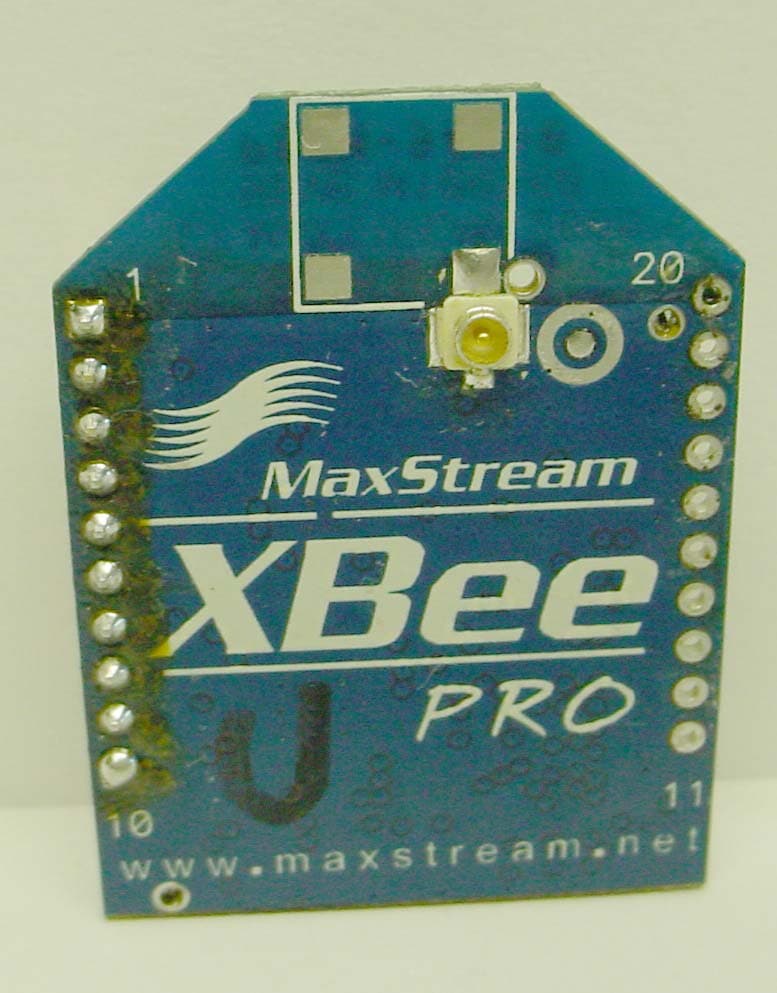
OUR-XBEEPRO
Nov 01, 2005XBEE-PRO OEM RF MODULE
Equipment Class
DTS - Digital Transmission System
OUR-9XCITE
Dec 16, 2003900 MHz Wireless OEM Module
Equipment Class
DTS - Digital Transmission System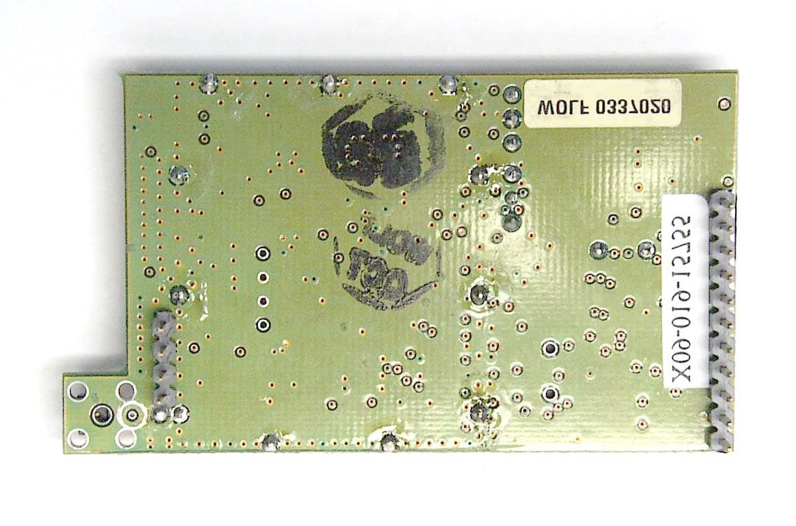
OUR9XSTREAM
Aug 05, 20029XSTREAM Wireless OEM Module
Equipment Class
DSS - Part 15 Spread Spectrum Transmitter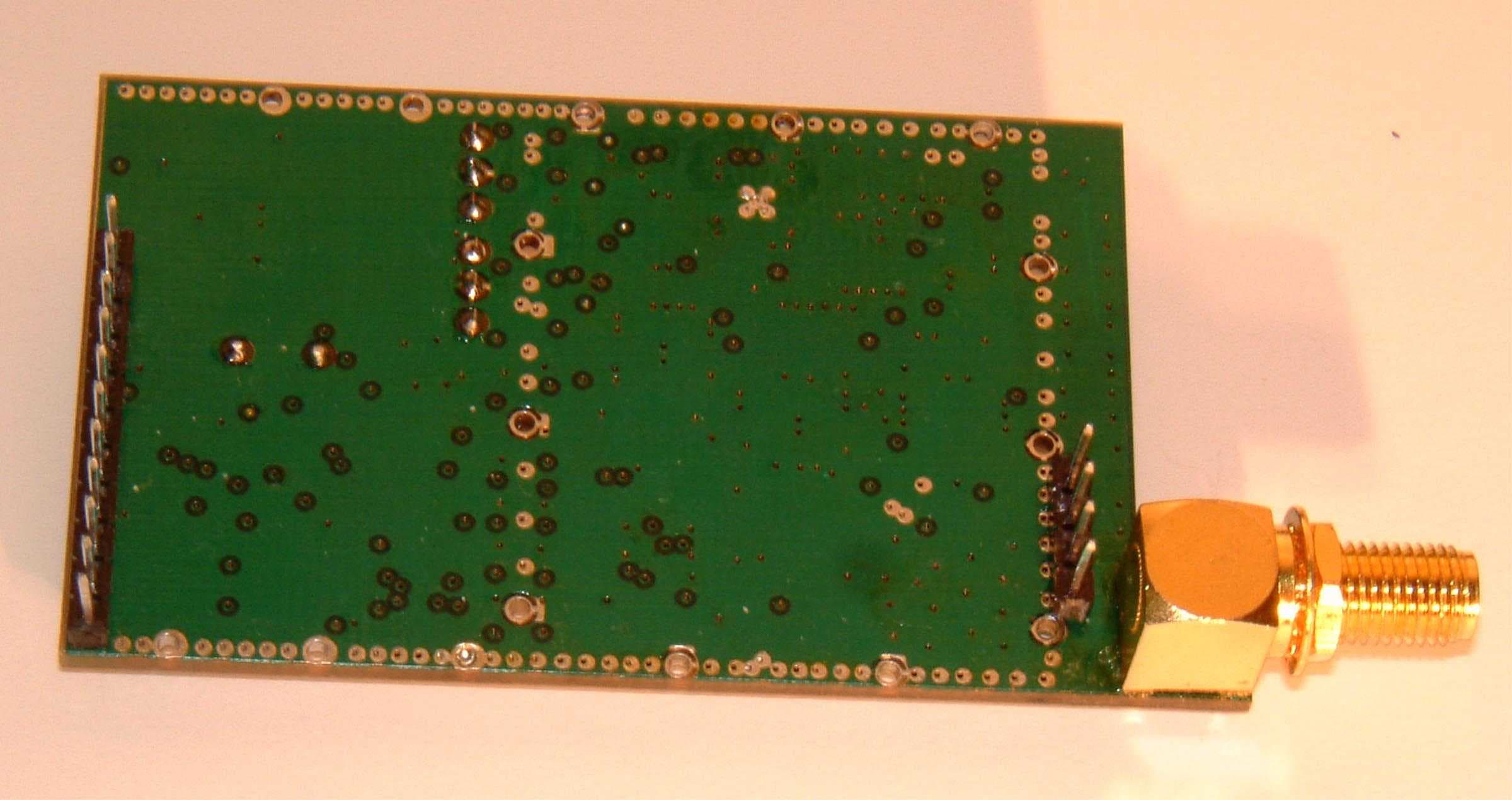
OUR-24XSTREAM
Feb 03, 200224XSTREAM
Equipment Class
DSS - Part 15 Spread Spectrum Transmitter
OUR9XTREAM
Jun 26, 2000DSS - Part 15 Spread Spectrum Transmitter
Equipment Class
DSS - Part 15 Spread Spectrum Transmitter