OUR9XTREAM
MaxStream Inc.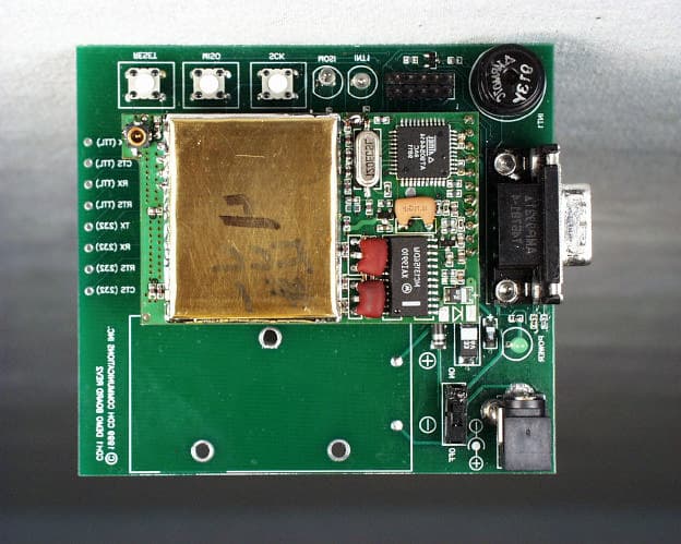
Click to zoom
Application Details
- Equipment Class
- DSS - Part 15 Spread Spectrum Transmitter
- Date of Grant
- Jun 26, 2000
- Application Purpose
- Original Equipment
- Date of Application
- Jan 03, 2000
- Frequency Range
- 910.50000000 - 917.70000000
- Company
- MaxStream Inc.
- Country
- United States
Documents & Files
Document Text
Text extracted from the exhibit documents filed with the FCC. Open a document above to read the original.
Users Manual
CDH Communications 9Xtream Frequency Hopping Data Radio CDH Communications 3471 N. 1730 W. Pleasant Grove, UT 84062 Phone: (801)796-5566 Fax: (801) 796-5525 http://www.cdhcommunications.com CDH Communications CDH Communications 3471 N. 1370 W. Pleasant Grove, UT 84062 (801)796-5566 9Xtreme Frequency Hopping Data Radio FCC Compliance Warning: Changes or modifications to the 9Xtreme Data Radio not expressly approved by CDH Communications, Inc. could void the user’s authority to operate this product. Note: This equipment has been tested and found to comply with the limits for a Class B digital device, pursuant to part 15 of the FCC Rules. These limits are designed to provide reasonable protection against harmful interference in a residential installation. This equipment generates, uses, and can radiate radio frequency energy and, if not installed and used in accordance with the instructions, may cause harmful interference to radio communications. However, there is no guarantee that interference will not occur in a particular installation. If this equipment does cause harmful interference to radio or television reception, which can be determined by turning the equipment off and on, the user is encouraged to try to correct the interference by one or more of the following measures: • Reorient or relocate the receiving antenna. • Increase the separation between the equipment and receiver. • Connect the equipment into an outlet on a circuit different from that to which the receiver is connected. • Consult the dealer or an experienced radio/TV technician for help. This device complies with part 15 of the FCC Rules. Operation is subject to the following two conditions: (1) This device may not cause harmful interference, and (2) This device must accept any interference received, including interference that may cause undesired operation. CDH Communications Introduction The CDH Communications 9Xtreme is a frequency hopping data transceiver radio designed for integration with other products. The 9Xtreme operates within the 900 MHz ISM Band under Part 15 of the FCC Rules and Regulations. The 9Xtreme allows OEMs to integrate the radio into their own systems. When installed using a CDH Communications approved antenna, the system integrator needs to make sure the 9Xtreme’s FCC label, or a copy of that FCC label, is clearly visible on the outside of the integrated product. Caution: If this radio is integrated into another product, the system integrator is responsible for complying with the external labeling requirements as directed in the FCC Rules and Regulations Part 15.19. The system integrator may only use antennas that have been tested and approved with this radio to maintain the FCC approval. If a system integrator uses a non-approved antenna they are responsible for obtaining their own FCC certification. The radio also requires +5V source voltage. Any voltage higher than 5.5V will damage the radio. Approved Antennas MfrModelFreqGainTypeConnectorDimensions Astron AXQ900 PTL 902-9282dBiOmniMMCX3” Astron AXH900 RP SMA R 902-9282dBiOmni Reverse Polarity SMA 6.5” CDH900CDAN902-9282dBiOmniIntegrated3” In order to comply with the FCC RF exposure requirements the Data Radio must be installed with the antennas listed above and a minimum separation distance of 20 cm must be maintained from the antenna to any near by persons. The Radio uses an asynchronous serial interface with a start bit, stop bit and eight (8) data bits at TTL levels for communicating with the host system. Using an RS232 driver chip (such as a Maxim MAX232) the Radio can communicate directly to a standard Serial Communications Port on a PC. See the section titled Demo Kit Instructions for a tutorial to help get started using the 9Xtreme Radio. 9Xtreme Features: • Frequency Hopping Spread Spectrum (FHSS) technology • Secure over the air data encryption • Resistant to noise and interference. • 130mW transmit power • 25 mile (40 Kilometer) effective range (line of sight) CDH Communications • Broadcast (promiscuous) networking protocol – data sent to the serial port on one radio will be presented out of the serial port on all other radios that are within range and have the same group code. Connections The Data Radio is connected to a host device using the 11 pin and the 4 pin berg headers. These connections provide the radio with the required DC power source (+5V) and allow the Data Radio to be programmed, configured and provide the I/O lines for the asynchronous line level (TTL) RS-232 connection. J1 PIN DESCRIPTIONS J1-1CTSClear to send flow control (output) J1-2INT1Interupt line to radio processor (input, not currently implemented) J1-3TXAsyncronous data output (data going from radio to user) J1-4RXAsyncronous data input (data going from user to radio) J1-5RTSReady to send flow control (input, not currently implemented) J1-6*RESETReset line to radio processor (pull low to reset radio processor) J1-7MOSISPI data in (input, not currently implemented) J1-8MISOSPI data out (output, not currently implemented) J1-9SCKSPI data clock (input/output, not currently implemented) J1-10Power+5 volts DC. (55mA in RX mode, 200mA in TX mode) J1-11Ground J2 PIN DESCRIPTIONS J2-1Ground J2-2Ground J2-3Ground J2-4Ground Antenna Connection Female MMCX CDH Communications Specifications Frequency Range:902 to 928 MHz ISM Band Radio Power Source:5 VDC 200mA Demo Kit Power Source:6-15 VDC 200mA Antenna Impedance:50 Ohms unbalanced Antenna Connection:MMCX female Operation Mode:Frequency Hopping Spread Spectrum Sensitivity:-111 dBm Selectivity:70 dB at pager and cellular frequencies FCC Compliance:Part 15 Transport Protocol:Transparent Data Interface:Asynchronous Serial TTL RF Data Rate:9600 bps Data Interface Rates:9600 or 19,200 bps Data Protocol:8 data bits, no parity, 1 stop bit, transparent (no protocol). Operating Temperatures: -40°C to 85°C, (-40°F to 185°F) Size:1.6 in. x 2.7 in. x .35 in. CDH Communications Using the 9Xtream Demo Kit Introduction: Use this dem…
Text truncated - open the document above for the full version.
Users Manual
CDH Communications 9Xtream Frequency Hopping Data Radio CDH Communications 3471 N. 1730 W. Pleasant Grove, UT 84062 Phone: (801)796-5566 Fax: (801) 796-5525 http://www.cdhcommunications.com CDH Communications CDH Communications 3471 N. 1370 W. Pleasant Grove, UT 84062 (801)796-5566 9Xtream Frequency Hopping Data Radio FCC Compliance Warning: Changes or modifications to the 9Xtream Data Radio not expressly approved by CDH Communications, Inc. could void the user’s authority to operate this product. Note: This equipment has been tested and found to comply with the limits for a Class B digital device, pursuant to part 15 of the FCC Rules. These limits are designed to provide reasonable protection against harmful interference in a residential installation. This equipment generates, uses, and can radiate radio frequency energy and, if not installed and used in accordance with the instructions, may cause harmful interference to radio communications. However, there is no guarantee that interference will not occur in a particular installation. If this equipment does cause harmful interference to radio or television reception, which can be determined by turning the equipment off and on, the user is encouraged to try to correct the interference by one or more of the following measures: • Reorient or relocate the receiving antenna. • Increase the separation between the equipment and receiver. • Connect the equipment into an outlet on a circuit different from that to which the receiver is connected. • Consult the dealer or an experienced radio/TV technician for help. This device complies with part 15 of the FCC Rules. Operation is subject to the following two conditions: (1) This device may not cause harmful interference, and (2) This device must accept any interference received, including interference that may cause undesired operation. CDH Communications Introduction The CDH Communications 9Xtream Radio is a frequency hopping data transceiver designed for integration with other products. The 9Xtream operates within the 900 MHz ISM Band under Part 15 of the FCC Rules and Regulations. Caution: If this radio is integrated into another product, the system integrator must make sure that the FCC label is visible from the outside of the final product, or that the external label provided with this device is placed on the outside of the final product. The system integrator may only use antennas that have been tested and approved with this radio to maintain the FCC approval. If a system integrator uses a non-approved antenna they are responsible for obtaining their own FCC certification. The radio also requires +5V source voltage. Any voltage higher than 5.5V will damage the radio. Approved Antennas Mfr Model Freq Gain Type Connector Dimensions Astron AXQ900 PTL 902-928 2dBi Omni MMCX 3” Astron AXH900 RP SMA R 902-928 2dBi Omni Reverse Polarity SMA 6.5” CDH 900CDAN 902-928 2dBi Omni Integrated 3” Caution: The 9XTREAM has been certified as a mobile device as per FCC Section 2.1091. In order to comply with the FCC RF exposure requirements the 9XTREAM must be installed with the antennas listed above and a minimum separation distance of 20 cm must be maintained from the antenna to any near by persons. If the OEM integrates the 9XTREAM into their final product, where the final product is classified as a portable device per FCC Section 2.1093 (less than 20 cm separation distance between the antenna to any near by persons). The OEM is responsible for obtaining a separate authorization on the final product. The Radio uses an asynchronous serial interface with a start bit, stop bit and eight (8) data bits at TTL levels for communicating with the host system. Using an RS232 driver chip (such as a Maxim MAX232) the Radio can communicate directly to a standard Serial Communications Port on a PC. See the section titled Demo Kit Instructions for a tutorial to get started using the 9Xtreme Radio. 9Xtreme Features: • Frequency Hopping Spread Spectrum (FHSS) technology • Secure over the air data encryption • Resistant to noise and interference. • 140mW transmit power • 20 mile (40 Kilometer) effective range (line of sight) • Broadcast (promiscuous) networking protocol – data sent to the serial port on one radio will be presented out of the serial port on all other radios that are within range and have the same group code. No two radios can transmit simultaneously, when one radio is transmitting, all others on the network will await a pause in transmissions. CDH Communications Connections The Data Radio is connected to a host device using the 11 pin and the 4 pin berg headers. These connections provide the radio with the required DC power source (+5V) and allow the Data Radio to be programmed, configured and provide the I/O lines for the asynchronous line level (TTL) RS-232 connection. J1 PIN DESCRIPTIONS J1-1 CTS Clear to send flow control (output) J1-2 INT1 Interupt line to radio processor (input, not currently implemented) J1-3 TX Asyncronous data output (data going from radio to user) J1-4 RX Asyncronous data input (data going from user to radio) J1-5 RTS Ready to send flow control (input, not currently implemented) J1-6 *RESET Reset line to radio processor (pull low to reset radio processor) J1-7 MOSI SPI data in (input, not currently implemented) J1-8 MISO SPI data out (output, not currently implemented) J1-9 SCK SPI data clock (input/output, not currently implemented) J1-10 Power +5 volts DC. (55mA in RX mode, 200mA in TX mode) J1-11 Ground J2 PIN DESCRIPTIONS J2-1 Ground J2-2 Ground J2-3 Ground J2-4 Ground Antenna Connection Female MMCX CDH Communications Specifications Frequency Range: 902 to 928 MHz ISM Band Radio Power Source: 5 VDC 200mA Demo Kit Power Source: 6-15 VDC 300mA Antenna Impedance: 50 Ohms unbalanced Antenna Connection: MMCX female Operation Mode: Frequency Hopping Spread Spectrum Sensitivity: -109 dBm Selectivity: 70 dB at pager and cellular frequencies FCC Compliance: Part 15 Transport Protocol: Tra…
Text truncated - open the document above for the full version.
Users Manual
9Xtream Frequency Hopping Data Radio CDH Communications 1206 S. 1680 W. Orem, UT 84058 Phone: (801) 765-9885 Fax: (801) 765-9895 http://www.cdhcommunications.com CDH Communications 1 CDH Communications 1206 S. 1680 W. Orem, UT 84058 Phone: (801) 765-9885 9Xtreme Frequency Hopping Data Radio FCC Compliance Warning: Changes or modifications to the 9Xtreme Data Radio not expressly approved by CDH Communications, Inc. could void the user’s authority to operate this product. Note: This equipment has been tested and found to comply with the limits for a Class B digital device, pursuant to part 15 of the FCC Rules. These limits are designed to provide reasonable protection against harmful interference in a residential installation. This equipment generates, uses, and can radiate radio frequency energy and, if not installed and used in accordance with the instructions, may cause harmful interference to radio communications. However, there is no guarantee that interference will not occur in a particular installation. If this equipment does cause harmful interference to radio or television reception, which can be determined by turning the equipment off and on, the user is encouraged to try to correct the interference by one or more of the following measures: • Reorient or relocate the receiving antenna. • Increase the separation between the equipment and receiver. • Connect the equipment into an outlet on a circuit different from that to which the receiver is connected. • Consult the dealer or an experienced radio/TV technician for help. This device complies with part 15 of the FCC Rules. Operation is subject to the following two conditions: (1) This device may not cause harmful interference, and (2) This device must accept any interference received, including interference that may cause undesired operation. CDH Communications 2 Introduction The 9XTREAM-192/96 radio is a 100-milliwatt frequency hopping wireless modem that communicates with other equipment using a standard 19200 or 9600 baud asynchronous serial data stream. The radio is half-duplex and can sustain close to a continuous data stream at the specified data rate. The 9XTREAM operates within the 900 MHz ISM Band under Part 15 of the FCC Rules and Regulations. Caution: If this radio is integrated into another product, the system integrator must make sure that the FCC label is visible from the outside of the final product, or that the external label provided with this device is placed on the outside of the final product. The system integrator may only use antennas that have been tested and approved with this radio to maintain the FCC approval. If a system integrator uses a non-approved antenna they are responsible for obtaining their own FCC certification. The radio also requires +5V source voltage. Any voltage higher than 5.5V will damage the radio. Approved Antennas Mfr Model Freq Gain Type Connector Dimensions Astron AXQ900 PTL 902-928 2dBi Omni MMCX 3” Astron AXH900 RP SMA R 902-928 2dBi Omni Reverse Polarity SMA 6.5” CDH 900CDAN 902-928 2dBi Omni Integrated 3” Caution: The 9XTREAM has been certified as a mobile device as per FCC Section 2.1091. In order to comply with the FCC RF exposure requirements the 9XTREAM must be installed with the antennas listed above and a minimum separation distance of 20 cm must be maintained from the antenna to any near by persons. If the OEM integrates the 9XTREAM into their final product, where the final product is classified as a portable device per FCC Section 2.1093 (less than 20 cm separation distance between the antenna to any near by persons). The OEM is responsible for obtaining a separate authorization on the final product. The Radio uses an asynchronous serial interface with a start bit, stop bit and eight (8) data bits at TTL levels for communicating with the host system. Using an RS232 driver chip (such as a Maxim MAX232) the Radio can communicate directly to a standard Serial Communications Port on a PC. See the section titled Demo Kit Instructions for a tutorial to help get started using the 9Xtreme Radio. 9Xtreme Features: • Frequency Hopping Spread Spectrum (FHSS) technology • Secure over the air data encryption • Resistant to noise and interference. • 100mW transmit power • Up to 25 mile (40 Kilometer) effective range (line of sight, 9600 baud) • Broadcast (promiscuous) networking protocol – data sent to the RX pin on one radio will be presented out of the TX pin of the serial port on all other radios that are within range and have the same network identifier code. CDH Communications 3 Connections The Data Radio is connected to a host device using the 11 pin and the 4 pin berg headers. These connections provide the radio with the required DC power source (+5V) and allow the Data Radio to be configured and provide the I/O lines for the asynchronous line level (TTL) RS-232 connection. J1 PIN DESCRIPTIONS J1-1 CTS Clear to send flow control (output) J1-2 INT1 Interrupt line to radio processor (input, not currently implemented) J1-3 TX Asynchronous data output (data going from radio to user) J1-4 RX Asynchronous data input (data going from user to radio) J1-5 RTS Ready to send flow control (input, not currently implemented) J1-6 *RESET Reset line to radio processor (assert low to reset radio processor) J1-7 MOSI SPI data in (input, not currently implemented) J1-8 MISO SPI data out (output, not currently implemented) J1-9 SCK SPI data clock (input/output, not currently implemented) J1-10 Power +5 volts DC. (55mA in RX mode, 200mA in TX mode) J1-11 Ground J2 PIN DESCRIPTIONS J2-1 Ground J2-2 Ground J2-3 Ground J2-4 Ground Antenna Connection Female MMCX CDH Communications 4 Operating States Scanning When the radio is neither transmitting nor receiving, it is continually scanning for valid transmissions. From the Scanning state the radio can either transmit, if data is presented on the serial port; or receive, if data is presented over the air. The radio will return to scanning when data is no l…
Text truncated - open the document above for the full version.
Cover Letter(s)
COMMUNICATION CERTIFICATION LABORATORYTEST REPORT: 73-7078 FCC ID: OUR9XTREAM Page 71 of 72 Exhibit 13 Exhibit 13: Cover Letters January 7, 2000 FEDERAL COMMUNICATIONS COMMISSION Equipment Authorization Division 7435 Oakland Mills Road Columbia, MD 21046 To Whom It May Concern: Enclosed is a FCC Part 15, Subpart C, Section 15.247 Certification application for the CDH Communications, Inc. Model 9XTREAM, FCC ID: OUR9XTREAM Please let me know if I can be of further assistance. Sincerely yours, COMMUNICATION CERTIFICATION LABORATORY Joseph W. Jackson V.P. Marketing COMMUNICATION CERTIFICATION LABORATORYTEST REPORT: 73-7078 FCC ID: OUR9XTREAM Page 72 of 72 Exhibit 13 Request for Confidentiality Letter
External Photos
COMMUNICATION CERTIFICATION LABORATORYTEST REPORT: 73-7078 FCC ID: OUR9XTREAM Page 5 of 72 Exhibit 3 Exhibit 3: Photographs of Overall Appearance Front View of the 9XTREAM and Interface Board COMMUNICATION CERTIFICATION LABORATORYTEST REPORT: 73-7078 FCC ID: OUR9XTREAM Page 6 of 72 Exhibit 3 Back View of the 9XTREAM and Interface Board COMMUNICATION CERTIFICATION LABORATORYTEST REPORT: 73-7078 FCC ID: OUR9XTREAM Page 7 of 72 Exhibit 3 Small Dipole Antenna COMMUNICATION CERTIFICATION LABORATORYTEST REPORT: 73-7078 FCC ID: OUR9XTREAM Page 8 of 72 Exhibit 3 Astron Model AXQ900 PTL Monopole Antenna COMMUNICATION CERTIFICATION LABORATORYTEST REPORT: 73-7078 FCC ID: OUR9XTREAM Page 9 of 72 Exhibit 3 Astron Model AXH900RP SMAR Dipole Antenna
ID Label/Location Info
COMMUNICATION CERTIFICATION LABORATORYTEST REPORT: 73-7078 FCC ID: OUR9XTREAM Page 1 of 72 Exhibit 1 Exhibit 1: FCC ID Label Equipment Identification Label In accordance with the requirements of Sections 15.19 (a), 2.925 and 2.926 of the FCC Rules, the following information will be permanently affixed to the CDH Communications, Inc. Model 9XTREAM as shown in the sketch on the following page. The 9XTREAM is to be certified as a module; therefore, the label shown on the following page will be provided with the 9XTREAM to be affixed on the outside of the host system which it is installed. Label to be placed on outside of host system COMMUNICATION CERTIFICATION LABORATORYTEST REPORT: 73-7078 FCC ID: OUR9XTREAM Page 2 of 72 Exhibit 1 RF Module Label and Label Placement COMMUNICATION CERTIFICATION LABORATORYTEST REPORT: 73-7078 FCC ID: OUR9XTREAM Page 3 of 72 Exhibit 1 The 9XTREAM can be sold with an interface board that provides a serial port for connection to a personal computer; therefore, in this configuration it is considered a computer peripheral and subject to the Declaration of Conformity requirements. Shown below is the Declaration of Conformity label that will be placed on the interface board. DoC Label and Label Placement (Interface Board)
Internal Photos
COMMUNICATION CERTIFICATION LABORATORYTEST REPORT: 73-7078 FCC ID: OUR9XTREAM Page 62 of 72 Exhibit 9 Exhibit 9: Internal Photographs Front View of the Interface Board COMMUNICATION CERTIFICATION LABORATORYTEST REPORT: 73-7078 FCC ID: OUR9XTREAM Page 63 of 72 Exhibit 9 Back View of the Interface Board COMMUNICATION CERTIFICATION LABORATORYTEST REPORT: 73-7078 FCC ID: OUR9XTREAM Page 64 of 72 Exhibit 9 Front View of the Radio Board (with RF Can Installed) COMMUNICATION CERTIFICATION LABORATORYTEST REPORT: 73-7078 FCC ID: OUR9XTREAM Page 65 of 72 Exhibit 9 Front View of the Radio Board (with RF Can Removed) COMMUNICATION CERTIFICATION LABORATORYTEST REPORT: 73-7078 FCC ID: OUR9XTREAM Page 66 of 72 Exhibit 9 Back View of the Radio Board
RF Exposure Info
COMMUNICATION CERTIFICATION LABORATORYTEST REPORT: 73-7078 FCC ID: OUR9XTREAM Page 68 of 72 Exhibit 11 Exhibit 11: RF Exposure/Environmental Evaluation The 9XTREAM can be installed with the three different types of antennas listed below: Approved Antennas MfrModelFreqGainTypeConnectorDimensions AstronAXQ900 PTL 902-9282dBiOmniMMCX3” AstronAXH900 RP SMA R 902-9282dBiOmniReverse Polarity SMA 6.5” CDH900CDAN902-9282dBiOmniIntegrated3” The 9XTREAM is sold to OEM’s for integration into their end products. The OEM’s are instructed in the user manual provided with each unit that the 9XTREAM is certified as a mobile device as per FCC Section 2.1091 and in order to comply with the RF exposure requirements the 9XTREAM must be installed with the antennas listed above and that a minimum 20-cm separation distance must always be maintained between the antenna and the user. If the OEM integrates the 9XTREAM into their final product, where the final product is classified as a portable device per FCC Section 2.1093 (less than 20 cm separation distance between the antenna to any near by persons). The OEM is responsible for obtaining a separate authorization on the final product. Therefore, the 9XTREAM complies with RF Exposure/Environmental Evaluation requirements. Enclosed below is a sample of the RF exposure statement that is contained in the user’s manual: Caution: The 9XTREAM has been certified as a mobile device as per FCC Section 2.1091. In order to comply with the FCC RF exposure requirements the 9XTREAM must be installed with the antennas listed above and a minimum separation distance of 20 cm must be maintained from the antenna to any near by persons. If the OEM integrates the 9XTREAM into their final product, where the final product is classified as a portable device per FCC Section 2.1093 (less than 20 cm separation distance between the antenna to any near by persons). The OEM is responsible for obtaining a separate authorization on the final product.
RF Exposure Info
Kwok: The user’s manual for the CDH Model 9XTREAM has been modified to include a warning statement regarding the minimum separation distance of 20 cm in order to comply with the RF exposure requirements. This new manual has been uploaded. Also enclosed below is your original question, for your reference. Re: FCC ID OUR9XTREAM Applicant: CDH Communications Inc. Correspondence Reference Number: 13728 731 Confirmation Number: EA96432 Date of Original E-Mail: 05/01/2000 Place your response in the RF exposure info folder of the electronic file. CDH, EA 96432: 1. Their response on 3/9/00 indicated they had included sample operating instructions and requirements for OEM integrators to provide end-users. Latest response on 4/4/00 indicates the sample instructions do not exist because there is no potential OEM customers at this time. This modular transmitter will be approved for mobile transmitting configurations with respect to 2.1091, the operating instructions for this transmitter to satisfy RF exposure requirements (MPE) should not be dependent on specific OEM products. Grantee should inform OEM integrators that they are required to include the specific end-user instructions as indicated by the grantee, for OEM products to satisfy RF exposure requirements. These end-user instructions should be located at an obvious of the final product manual and similar to the following - "IMPORTANT: This device operates with a modular transmitter that must satisfy FCC RF exposure compliance requirements for mobile transmitting devices. The antenna of this device (modular transmitter) must be installed and operated with a separation distance of 20 cm or more from persons to satisfy the RF exposure requirements. Operations that do not meet these requirements must be avoided." Please upload the above. Proposed Grant Condition - This modular transmitter is approved for integration into products operating according to requirements of 2.1091.
RF Exposure Info
9Xtream Frequency Hopping Data Radio CDH Communications 1206 S. 1680 W. Orem, UT 84058 Phone: (801) 765-9885 Fax: (801) 765-9895 http://www.cdhcommunications.com CDH Communications 1 CDH Communications 1206 S. 1680 W. Orem, UT 84058 Phone: (801) 765-9885 9Xtreme Frequency Hopping Data Radio FCC Compliance Warning: Changes or modifications to the 9Xtreme Data Radio not expressly approved by CDH Communications, Inc. could void the user’s authority to operate this product. Note: This equipment has been tested and found to comply with the limits for a Class B digital device, pursuant to part 15 of the FCC Rules. These limits are designed to provide reasonable protection against harmful interference in a residential installation. This equipment generates, uses, and can radiate radio frequency energy and, if not installed and used in accordance with the instructions, may cause harmful interference to radio communications. However, there is no guarantee that interference will not occur in a particular installation. If this equipment does cause harmful interference to radio or television reception, which can be determined by turning the equipment off and on, the user is encouraged to try to correct the interference by one or more of the following measures: • Reorient or relocate the receiving antenna. • Increase the separation between the equipment and receiver. • Connect the equipment into an outlet on a circuit different from that to which the receiver is connected. • Consult the dealer or an experienced radio/TV technician for help. This device complies with part 15 of the FCC Rules. Operation is subject to the following two conditions: (1) This device may not cause harmful interference, and (2) This device must accept any interference received, including interference that may cause undesired operation. CDH Communications 2 Introduction The 9XTREAM-192/96 radio is a 100-milliwatt frequency hopping wireless modem that communicates with other equipment using a standard 19200 or 9600 baud asynchronous serial data stream. The radio is half-duplex and can sustain a continuous data stream at the specified data rate. The 9XTREAM operates within the 900 MHz ISM Band under Part 15 of the FCC Rules and Regulations. IMPORTANT: The 9XTREAM radio has been certified by the FCC as a module for integration into OEM products without further certification being necessary (as per FCC section 2.1091.) The OEM must satisfy the following requirements in order to comply with FCC regulations: 1) The system integrator must ensure that the external label provided with this device is placed on the outside of the final product. 2) In order to comply with the FCC RF exposure requirements, the 9XTREAM may be used only with Approved Antennas that have been tested with this radio and a minimum separation distance of 20 cm must be maintained from the antenna to any near by persons. The OEM must also include a statement in the final product manual, informing users of the requirement to maintain 20 cm separation from the antenna to any near by persons. If the OEM integrates the 9XTREAM into their final product, where the final product utilizes a non-approved antenna or is classified as a portable device per FCC Section 2.1093 (less than 20 cm separation distance between the antenna to any near by persons,) the OEM is responsible for obtaining a separate authorization on the final product. 3) The 9XTREAM radio requires a regulated 5-volt, 200mA supply for operation. Any voltage higher than 5.5 volts will damage the radio. Approved Antennas Mfr Model Freq Gain Type Connector Dimensions Astron AXQ900 PTL 902-928 2dBi Omni MMCX 3” Astron AXH900 RP SMA R 902-928 2dBi Omni Reverse Polarity SMA 6.5” CDH 900CDAN 902-928 2dBi Omni Integrated 3” External Label CDH Communications 3 The Radio uses an asynchronous serial interface with a start bit, stop bit and eight (8) data bits at TTL levels for communicating with the host system. Using an RS232 driver chip (such as a Maxim MAX232) the Radio can communicate directly to a standard Serial Communications Port on a PC. See the section titled Demo Kit Instructions for a tutorial to help get started using the 9Xtreme Radio. 9Xtreme Features: • Frequency Hopping Spread Spectrum (FHSS) technology • Secure over the air data encryption • Resistant to noise and interference. • 100mW transmit power • Up to 25 mile (40 Kilometer) effective range (line of sight, 9600 baud) • Broadcast (promiscuous) networking protocol – data sent to the RX pin on one radio will be presented out of the TX pin of the serial port on all other radios that are with…
Text truncated - open the document above for the full version.
Contact Information
Applicant
Paul Dahl(Hardware Manager)
Technical Contact
Communication Certification LaboratoryRoger J Midgley
[email protected](801) 972-6146
1940 W. Alexander Street · Salt Lake City, Utah · United States
Test Firm
Communication Certification Lab.Scott Earl
Technical Specifications
| # | Rule Parts | Frequency Range | Power Output |
|---|---|---|---|
| 1 | 15C | 910.5 MHz - 917.7 MHz | 141.00 mW |
Other Applications from MaxStream Inc.
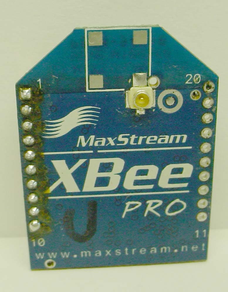
OUR-XBEEPRO
Nov 01, 2005XBEE-PRO OEM RF MODULE
Equipment Class
DTS - Digital Transmission System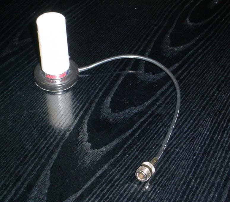
OUR-9XTEND
Nov 14, 20049XTEND OEM RF Module
Equipment Class
DSS - Part 15 Spread Spectrum Transmitter
OUR-9XCITE
Dec 16, 2003900 MHz Wireless OEM Module
Equipment Class
DTS - Digital Transmission System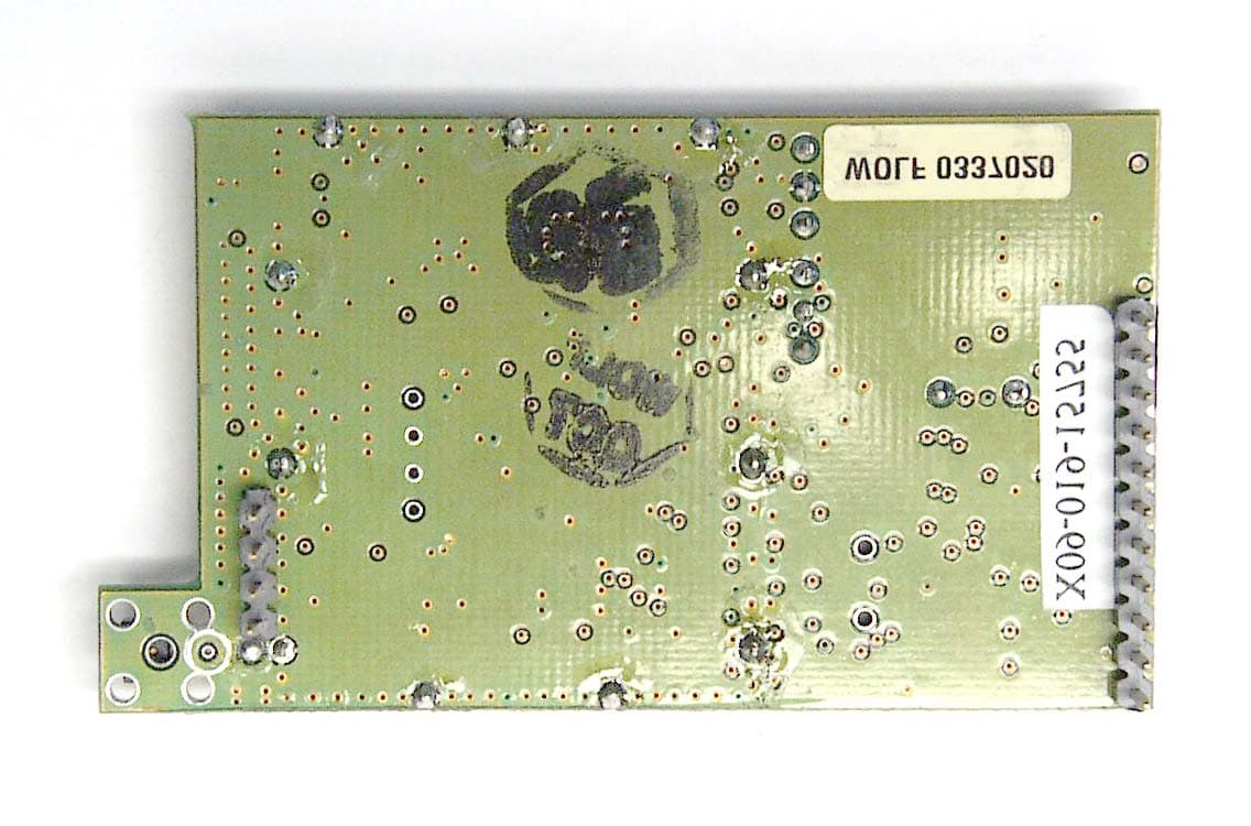
OUR9XSTREAM
Aug 05, 20029XSTREAM Wireless OEM Module
Equipment Class
DSS - Part 15 Spread Spectrum Transmitter
OUR-24XSTREAM
Feb 03, 200224XSTREAM
Equipment Class
DSS - Part 15 Spread Spectrum Transmitter