OV5-PF80452JDLINK Machine Messenger
Deere & Company dba John Deere Intelligent Solutions Group
Click to zoom
Application Details
- Equipment Class
- TNB - Licensed Non-Broadcast Station Transmitter
- Date of Grant
- Apr 23, 2002
- Application Purpose
- Original Equipment
- Date of Application
- Apr 23, 2002
- Equipment Note
- JDLINK Machine Messenger
- Frequency Range
- 824.00000000 - 849.00000000
- Country
- United States
Documents & Files
Document Text
Text extracted from the exhibit documents filed with the FCC. Open a document above to read the original.
Users Manual
JDLINKMachine Messenger INSTALLATION INSTRUCTIONS JDLINK Machine Messenger PC20103 09JAN02 (ENGLISH) 8020, 9020 John Deere Ag Management Solutions PC20103 (09JAN02) COPYRIGHT2001 DEERE & COMPANY Moline, Illinois All rights reserved A John Deere ILLUSTRUCTION Manual PC20103-19-09JAN02 P R O O F P R O O F Installation Instructions DX,ALERT –19–29SEP98–1/1 Recognize Safety Information T81389 –UN–07DEC88 This is a safety-alert symbol. When you see this symbol on your machine or in this manual, be alert to the potential for personal injury. Follow recommended precautions and safe operating practices. OUO6091,0001435 –19–20AUG01–1/1 JDLINK Wiring Harness Reference PC6783 –UN–19DEC01 PC6782 –UN–19DEC01 A—Socket Connector To Controller B—CAN Bus Terminator Connector C—Ground wire D—CCD Bus Connector E—CAN Bus Terminator Connector F—Unswitched And Switch Power Wires G—SCV Panel Connector H—10 Amp Fuses (09JAN02)1Installation Instructions 010902 PN=3 P R O O F P R O O F Installation Instructions OUO6091,0001433 –19–14AUG01–1/27 Install JDLINKMachine Messenger IMPORTANT: Avoid damage to electrical system of tractor when installing JDLINK wiring harness. Disconnect battery ground. NOTE: After installing JDLINK Machine Messenger and before reassembling cab roof, login to JDLINK website at www.jdlink.com, go to Dealer Menu/Setup New Device wizard and follow online procedures. These procedures will allow JDLINK communication controller’s serial number to be verified and tractor’s serial number to be entered for proper system operation. Reference of JDLINK Machine Messenger’s Technical Manual is required for this instruction. 1. Shut off engine, set parking brake and remove key. JDLINK is a trademark of Deere & Company Continued on next page (09JAN02)2Installation Instructions 010902 PN=4 P R O O F P R O O F Installation Instructions OUO6091,0001433 –19–14AUG01–2/27 PC6928 –UN–28NOV01 PC6929 –UN–28NOV01 PC6931 –UN–29NOV01 PC6930 –UN–28NOV01 A—TORX Screws B—Plastic Rivets C—Cap Screw D—Screws E—Console Cover NOTE: If tractor is equipped with JDLINK wiring harness go to step 11. 2. Remove TORX screws (A). 3. Remove plastic rivets (B). 4. Remove cap screw (C). NOTE: To access console screws (D), remove fuse panel cover. 5. Remove screws (D) and console cover (E). TORX is a trademark of Camcar/Textron (09JAN02)3Installation Instructions 010902 PN=5 P R O O F P R O O F Continued on next page Installation Instructions OUO6091,0001433 –19–14AUG01–3/27 PC6764 –UN–14AUG01 A—Shroud Screws B—Post Shroud 6. Remove right rear shroud screws (A) and shroud (B). OUO6091,0001433 –19–14AUG01–4/27 PC6934 –UN–28NOV01 A—Screw B—Light C—Trim Screws D—Trim NOTE: Remove headliner enough to route wiring harness down right-rear corner post. 7. Remove screw (A), light (B), trim screws (C) and headliner trim (D). OUO6091,0001433 –19–14AUG01–5/27 PC6933 –UN–28NOV01 A—Rear Window Molding 8. Remove right rear window molding (A). OUO6091,0001433 –19–14AUG01–6/27 PC6766 –UN–28NOV01 A—Screw B—Panel Spacer C—SCV Panel 9. Remove screw (A), panel spacer (B) and SCV setup panel (C). (09JAN02)4Installation Instructions 010902 PN=6 P R O O F P R O O F Continued on next page Installation Instructions OUO6091,0001433 –19–14AUG01–7/27 PC6767 –UN–19DEC01 A—CAN Bus Terminator NOTE: CAN bus terminator will be reinstalled on roof of cab in a following step. 10. Disconnect and remove CAN bus terminator (A). OUO6091,0001433 –19–14AUG01–8/27 PC6762 –UN–14AUG01 A—Cap Screws B—Mirror 11. Remove flange cap screws (A) and mirror (B). 12. Disconnect and remove STARFIREreceiver, if equipped. NOTE: Refer to machine Technical Manual for removal of rear cab lights and radio antenna. 13. Remove rear cab lights and disconnect radio antenna. STARFIRE is a trademark of Deere & Company OUO6091,0001433 –19–14AUG01–9/27 PC6763 –UN–14AUG01 A—Cap Screws (16 used) B—Cap Screws (2 used) C—Cab Roof NOTE: Cab roof is awkward to handle, use suitable lifting device or two technicians. 14. Remove cap screws (A and B), washers and cab roof (C). Continued on next page (09JAN02)5Installation Instructions 010902 PN=7 P R O O F P R O O F Installation Instructions OUO6091,0001433 –19–14AUG01–10/27 PC6781 –UN–20AUG01 PC6771 –UN–20AUG01 A—Coax B—Coax C—Antenna Assembly D—Cap Screws 15. Connect coax cables (A and B) to antenna assembly (C). IMPORTANT: Improperly installed antenna and receiver may interfere with the operation of machine’s electronic system and possibly subject operator to higher than recommended radio frequency emission levels. 16. Attach antenna assembly to right rear-window hinge using existing cap screws (D). OUO6091,0001433 –19–14AUG01–11/27 PC6938 –UN–29NOV01 Reference Of 8020 A—Coax Cable B—Antenna Assembly C—Controller NOTE: For all machines, route coax cables on right side of cab. 17. Route coax cables (A) on right side of tractor cab from antenna assembly (B) to controller (C). Continued on next page (09JAN02)6Installation Instructions 010902 PN=8 P R O O F P R O O F Installation Instructions OUO6091,0001433 –19–14AUG01–12/27 PC6768 –UN–14AUG01 PC6769 –UN–16AUG01 PC6760 –UN–10AUG01 Template (Reference Only) A—Template B—Hole Guides NOTE: Use pullout templates (included with this instruction) to locate and drill holes at left front section of cab. Templates below are for reference only. If tractor is equipped with JDLINK wiring harness, skip to step 21. 18. Install templates (A) and tape corners of templates to brackets. Locate and mark four holes (B) for drilling. 19. Remove templates. 20. Drill four 8 mm (5/16 in) holes (B). (09JAN02)7Installation Instructions 010902 PN=9 P R O O F P R O O F Continued on next page Installation Instructions OUO6091,0001433 –19–14AUG01–13/27 PC6773 –UN–28NOV01 21. Attach coax cables (A) to controller (B). 22. Connect JDLINK wiring harness connector (C) to controller and tighten cap screw (D). NOTE: Record controller’s 13 digit serial number for a following step. 23. Install terminator (E) and retain with tie straps. OUO6…
Text truncated - open the document above for the full version.
Block Diagram
Communication Controller Block Diagram Pull Plug Frequency Input Conditioning Digital Outputs Analog Input Scaling Digital Input Cinch Connector (581-01-30-001) Auxiliary Connections (for CI) CI Wireless Link CVDM-2000 SAFC167 (16 MHz) GPS Antenna Connector Cellular Antenna Connector RS-232 Interface Chip MAX232E Voltage Regulator DUART ST16C2552 (1.8432 MHz) Flash Memory Application Code Flash Memory Flight Recorder RAM Application Code RAM Flight Recorder EEPROM CAN Interface chip PCA82C251D CCD Interface Chip DCP68HC68S1 Ignition Real-Time Clock (32.768 kHz) Low Voltage Detect I/O
External Photos
JDLink front / side view JDLink back/side view JDLink connector detail JDLink top JDLink with antennas and harnessing JDLink cell and GPS antennas with mounting bracket
ID Label/Location Info
FCC Label Location FCC Label Detail
Internal Photos
JDLink with top half of enclosure removed Communications Interface (Modem & GPS) PCB assembly with mounting plate Communications Interface PCB assembly (top) Communications Interface PCB with RF Shield removed (top) Communications Interface PCB assembly (bottom) Communications Interface PCB with RF shield removed (bottom) GPS module (top) GPS module (bottom) GPS module with RF shield removed (top) GPS module with RF shield removed (bottom) Machine Interface PCB in enclosure with Communications Interface PCB removed Machine Interface PCB (top) Machine Interface PCB (bottom) DeereTrax with top half of enclosure removed Communications Interface (Modem & GPS) PCB assembly with mounting plate Communications Interface PCB assembly (top) Communications Interface PCB with RF Shield removed (top) Communications Interface PCB assembly (bottom) Communications Interface PCB with RF shield removed (bottom) GPS module (top) GPS module (bottom) GPS module with RF shield removed (top) GPS module with RF shield removed (bottom) Machine Interface PCB in enclosure with Communications Interface PCB removed Machine Interface PCB (top) Machine Interface PCB (bottom) DeereTrax with top half of enclosure removed, showing Communications Interface PCB – view #1 DeereTrax with top half of enclosure removed, showing Communications Interface PCB – view #2 Bottom view of Communications Interface PCB mounting plate Machine Interface PCB (top) Machine Interface PCB (bottom)
Internal Photos
DeereTrax with top half of enclosure removed JDLink with top half of enclosure removed Communications Interface (Modem & GPS) PCB assembly with mounting plate Communications Interface PCB assembly (top) Communications Interface PCB with RF shields removed (top) Communications Interface PCB assembly (bottom) Communications Interface PCB with RF shield removed (bottom) GPS module (top) GPS module (bottom) GPS module with RF shield removed (top) GPS module with RF shield removed (bottom) Machine Interface PCB in enclosure with Communications Interface PCB removed Machine Interface PCB (top) Machine Interface PCB (bottom) Communications Interface (Modem & GPS) PCB assembly with mounting plate Communications Interface PCB assembly (top) Communications Interface PCB with RF shields removed (top) Communications Interface PCB assembly (bottom) Communications Interface PCB with RF shield removed (bottom) GPS module (top) GPS module (bottom) GPS module with RF shield removed (top) GPS module with RF shield removed (bottom) Machine Interface PCB in enclosure with Communications Interface PCB removed Machine Interface PCB (top) Machine Interface PCB (bottom)
Operational Description
JDLINK OPERATIONAL DESCRIPTION DEERE & COMPANY Confidential and ProprietaryPAGE 1 OF 4 JDLink Communications Controller Operational Description Phoenix International Corporation A John Deere Company JDLINK OPERATIONAL DESCRIPTION DEERE & COMPANY Confidential and ProprietaryPAGE 2 OF 4 1. Introduction The John Deere JDLink product is a stand-alone device that can be installed on various types of John Deere agricultural equipment. JDLink consists of a Communications Controller in an aluminum enclosure, an installation harness, GPS and cell phone antennas, and an antenna mounting bracket. The unit runs off of vehicle power (alternator / battery). JDLink provides the operator/owner with a way to remotely monitor machine status. This is accomplished by the Communications Controller monitoring CAN (Controller Area Network), CCD (Chrysler Collision Detection), and / or RS- 232 serial busses on the equipment. The Communications Controller also has various digital and analog inputs that can be configured for specific tasks. The Communications Controller gathers the following types of vehicle information: ∑ Location information via GPS ∑ Vehicle engine hours ∑ Three types of machine alerts (up to 499 total alerts) ∑ “Red” or Stop Engine alerts, which can be configured to generate an immediate call-in if the user desires, ∑ “Yellow” or Caution alerts, which are alerts that do not require immediate action, ∑ “Signal” alerts, which are specific to the JDLink Communications Controller unit. This information is sent back to a centralized server (called the Communications Server) via a cell phone modem. The user can then access this information via the World Wide Web using a web browser. The user also configures the Communications Controller using the same web interface – the Communications Controller has no operating controls on the unit. The Communications Server can also initiate a call to the Communications Controller. This is done for two reasons - retrieving the current vehicle status and updating configuration information. 2. Communications Controller Architecture The Communications Controller consists of two main components, the Communications Interface and the Machine Interface. The Communications Interface is an off-the-shelf AMPS (Advanced Mobile Phone System) cellular modem operating at 824 - 849 MHz, and an integrated GPS (Global Positioning System) receiver. It is responsible for initiating and receiving calls from the Communications Server and obtaining GPS position information. The Machine Interface is responsible for gathering information from the vehicle via CAN, CCD, RS-232, and/or discrete inputs, providing regulated power to the Communications Controller, and packaging all data appropriately for over-the-air transmission. The Machine Interface and the Communications Interface communicate via an RS-232 serial interface. A block diagram of the Communications Controller is shown below. COMMUNICATIONS CONTROLLER CELLULAR ANTENNA GPS ANTENNA PLUG PULL INPUT ANALOG INPUTS COMMUNICATIONS INTERFACE MACHINE INTERFACE RS232 INTERFACE CAN BUS CCD BUS MACHINE IGNITION MACHINE BATTERY OPTO-ISOLATED INPUT JDLINK OPERATIONAL DESCRIPTION DEERE & COMPANY Confidential and ProprietaryPAGE 3 OF 4 In addition to performing all wireless communications, the Communications Interface has the capability of monitoring two additional inputs, one dedicated to vehicle ignition and a generic opto-isolated input. The user can configure the Communications Controller to take specific actions based on the state of these inputs. Note that connection of the opto- isolated input to an external device is optional and does not apply to all installations. The Machine Interface has three inputs in addition to buss monitoring and power regulation / distribution. Two inputs are generic analog inputs. The user can configure the Communications Controller to take specific actions based on the state of these inputs. The third input is a dedicated Plug-Pull input that can be used to initiate a call to the Communications Server. Note that connection of the analog inputs and the Plug-Pull input is optional and does not apply to all installations. The Machine Interface also has a Real Time Clock (RTC) that is used to time-stamp bus information and for call-in scheduling. 3. Call-In Scheduling The call-in schedule for the Communications Controller can be configured via the World Wide Web interface. Call-ins can be scheduled with a minimum interval between calls of one hour, and a maximum interval between calls of one week. The maximum transmission time per connection is 3 hours. Call-ins can occur independent of the operational state of the vehicle (vehicle ignition on or off). If there is no data to report, the Communications Controller will skip call-ins until there is new data. In the event that the Communications Controller is unable to contact the Communications Server, the Communications Controller will try to contact the Communications Server based on the retry logic shown below: If the initial call-in is unsuccessful then: ∑ 2 nd Attempt will be made 56 seconds after 1 st attempt fails ∑ 3 rd Attempt will be made 6 minutes after 2 nd attempt fails ∑ 4 th Attempt will be made 56 seconds after 3 rd attempt fails ∑ 5 th Attempt will be made 6 minutes after 4 th attempt fails ∑ 6 th Attempt will be made 56 seconds after 5 th attempt fails ? – denotes undetermined amount of time for call attempt to fail The Communications Controller can also be forced into a Hold mode in which no call-ins are generated. 4. Power Management The Communications Controller has four power management modes: Full Power, Ears On, Power-Save, and Power Off. The Communications Controller is in Full Power mode when the vehicle ignition is on. In this mode, the Machine Interface is fully operational and the Communications Interface is ready to receive calls from the Communications Server. In Ears On mode, the Machine Interface is in a low power state, but the …
Text truncated - open the document above for the full version.
Parts List/Tune Up Info
Printed On: 02-19-02 Phoenix International Corporation - Fargo PAGE 1 Effective Date: 02-19-02 Indented Bill of Material (PICBOM) 90-128005 JD AG SIGNAL COMM CTRLR Item Part Number.... Quantity. Hold Rev UOM Description.............. Manufacturer's P/N...................... EFF DATE 2 36-133307-001 1.0000 Q 01 EA GVC, PROG'D WIRELESS LINK 11-29-01 36 52-133308-001 REF A EA DECAL JD LINK ASSEMBLY 01-09-02 38 52-133591-001 REF B EA DECAL, FCC COMPLI JD LINK 01-28-02 41 52-133632-001 REF A EA DECAL, SOFTWARE REVISIONS 01-28-02 40 53-121634 1.0000 EA DECAL P/N LABEL MATERIAL 01-28-02 37 53-133490-001 1.0000 A EA DECAL 2.75 X 1.75 TT733 01-09-02 39 53-133631-001 1.0000 A EA DECAL, 2.00 X 1.75 TT702 01-28-02 7 70-118772 0.0083 GL CHEM COAT DOW 3-1753 PAIL DOW*3-1753 (BLADDER PACK) 11-29-01 8 75-126094 1.0000 EA PAC BAG 10X15.5 ULINE*S-532 11-29-01 9 800-0264 2.0000 EA RAIL, GVC-0001 11-29-01 10 800-0265 1.0000 EA PLATE W/ INSERTS, GVC-1 11-29-01 14 81-117970 8.0000 EA STFPNTN06U320SZ006 12-06-01 15 81-117971 4.0000 EA STFPNTN10U320SZ016 11-29-01 16 81-117976 4.0000 EA STFPNTN04T200SY008 ADMSNB*81-117976 11-29-01 18 812-0040 4.0000 EA PHMS, PHIL, 4-40 X .50 MCMAST*90272A110 02-12-02 20 812-0073 4.0000 EA PHMS, PHIL, 8-32 X .625 MCMAST*90272A196 01-28-02 22 819-0022 4.0000 EA SCREW, 6/32X1/2 FH THDFMG ROSE*0608RPF 01-28-02 27 83-110710 4.0000 EA WFL---N040125SZ032-00312 01-09-02 25 83-133011-001 4.0000 A EA W FL---N080171L-065-00625 11-29-01 29 840-0115 4.0000 EA SPCR, ALUM RND 3/8" #8 MCMAST*92510A305 01-28-02 30 840-0116 4.0000 EA SPCR, SPECIAL FOR GVC 11-29-01 6 881-0010 4.0000 EA GROMMET, OD=.750 ID=.245 EAR*G-601-V-2325# 01-28-02 32 91-133396 REF EA SFW 10119 P R1.0 CI CFG 12-11-01 1_1_14_20011105.CVD 33 91-133398 REF EA SFW 10119 P R1.0 CI CVDM 12-11-01 CVDM_01_00_00-19-JAN-00.BIN 34 91-133399 REF EA SFW 10119 P R1.0 CI FCP 12-11-01 FCP_01_02_05-25-APRIL-01.MOT 35 91-133400 REF EA SFW 10119 P R1.0 CI SID 12-11-01 1_7_00_20011010.TXT Printed On: 02-19-02 Phoenix International Corporation - Fargo PAGE 2 Effective Date: 02-19-02 Indented Bill of Material (PICBOM) 90-128005 JD AG SIGNAL COMM CTRLR Item Part Number.... Quantity. Hold Rev UOM Description.............. Manufacturer's P/N...................... EFF DATE 12 93-133506-001 1.0000 Q A EA OSC SER MA 61-119416 01-09-02 1 .61-119416C 1.0000 EA ENCL C 241X179X38 MM A - 01-14-02 31 95-119405 1.0000 EA ASSY BLANK WEDGE BOX 11-29-01 2 .61-117908C 1.0000 EA ENCL C 241X179X38 MM A - 03-11-99 BLANK 7 .70-126719 0.0092 LB CHEM RTVS LOCTITE 5910 LOCTIT*21747 06-19-01 1 95-128007 1.0000 EA PCB ASSY COMM CTRLR W01 11-26-01 1 .10-117710 2.0000 EA RES S 1001 R100 01 MCF DALE*CRCW08051001F# 11-17-00 R103,125 2 .10-117714 6.0000 EA RES S 4751 R100 01 MCF DALE*CRCW08054751F# 11-17-00 R16,86,97,100,101,181 4 .10-117716 30.0000 EA RES S 1002 R100 01 MCF DALE*CRCW08051002F# 12-06-01 R8,11,14,39,66,67,78-81,87,91,94,95,102, 105,123,127,130,140-144,147,151-154,162 5 .10-117719 15.0000 EA RES S 2002 R100 01 MCF DALE*CRCW08052002F# 11-17-00 R15,65,70,92,96,168-173,182-185 6 .10-117723 11.0000 EA RES S 1003 R100 01 MCF DALE*CRCW08051003F# 11-17-00 R32,84,85,89,90,163-167,175 7 .10-117998 5.0000 EA RES S 4752 R100 01 MCF DALE*CRCW08054752F# 11-17-00 R13,148,159,174,177 8 .10-118955 2.0000 EA RES S 1743 R100 01 MCF DALE*CRCW08051743F# 11-17-00 R64,69 9 .10-119390 2.0000 EA RES S 1200 R125 05 MCF DALE*CRCW1206121J# 11-17-00 R27,28 10 .10-119686 9.0000 EA RES S 7501 R100 01 MCF DALE*CRCW08057501F# 11-17-00 R106,112,113,118,120,160,178-180 49 .10-120066 2.0000 EA RES S 3012 R100 01 MCF DALE*CRCW08053012F# 06-13-01 R75,77 Printed On: 02-19-02 Phoenix International Corporation - Fargo PAGE 3 Effective Date: 02-19-02 Indented Bill of Material (PICBOM) 90-128005 JD AG SIGNAL COMM CTRLR Item Part Number.... Quantity. Hold Rev UOM Description.............. Manufacturer's P/N...................... EFF DATE 11 .10-121028 2.0000 EA RES S 1501 R500 05 MCF DALE*CRCW2010152J# 11-17-00 R1,5 12 .10-121133 9.0000 EA RES S 2211 R100 01 MCF DALE*CRCW08052211F# 11-17-00 R30,35,40,46,49,55,187-189 48 .10-124804 2.0000 EA RES S 3920 R100 01 MCF DALE*CRCW08053920F# 11-29-01 R158,186 13 .10-128040 2.0000 EA RES S 0560 R500 05 MCF DALE*CRCW2010560J# 11-17-00 R18,22 14 .10-128573 4.0000 EA RES S 4423 R100 01 MCF DALE*CRCW08054423F# 11-17-00 R63,68,88,93 50 .15-117725 2.0000 EA CAP S 0220 050 05 MLC COG MUR*GRM40-COG220J050# 06-13-01 C16,17 15 .15-117727 4.0000 A EA CAP S 1001 050 10 MLC X7R KEMET*CO805C102K5RAC# 11-17-00 C2,48,59,60 16 .15-117730 22.0000 EA CAP S 1002 050 10 MLC X7R MUR*GRM40-X7R103K050# 11-17-00 C6,9,28,38,52,54,61,68,71,73,74,80,81, 83,90,92,97,100,116,147,166,167 17 .15-118186 3.0000 EA CAP S 3301 050 10 MLC X7R MUR*GRM40X7R332K050# 11-17-00 C20,67,113 18 .15-119164 8.0000 EA CAP S 1004 016 10 TAN N SPRAG*293D105X9016A2T 11-17-00 C5,47,50,55,119,153,154,157 19 .15-120212 36.0000 EA CAP S 1003 050 10 MLC X7R KEMET*C0805C104K5RAC# 11-17-00 C11,27,30,49,57,58,65,69,76,77,84,94, 106-108,120-124,126,130,131,136-142,144, 148-151,168 20 .15-121014 1.0000 EA CAP S 2205 016 20 TAN N KEMET*T491C226M016AS 11-17-00 C21 21 .15-122327 1.0000 EA CAP S 1002 100 10 MLC X7R KEMET*C1206C103K1RAC# 11-17-00 C75 22 .15-122836 1.0000 EA CAP S 1004 016 10 MLC X7R PHIL*12062R105K7#0 11-28-00 C31 62 .15-124441 1.0000 EA CAP S 1006 016 20 TAN AVX*TPSE107M016#0100 06-14-01 Printed On: 02-19-02 Phoenix International Corporation - Fargo PAGE 4 Effective Date: 02-19-02 Indented Bill of Material (PICBOM) 90-128005 JD AG SIGNAL COMM CTRLR Item Part Number.... Quantity. Hold Rev UOM Description.............. Manufacturer's P/N...................... EFF DATE C146 51 .15-125479 1.0000 EA CAP S 2206 050 20 ELE NON NIC*NACZ221M50V10X10.5# 06-13-01 C145 59 .17-130253 1.0000 EA IND S 0150 CCRAFT*DO5022P-154# 06-13-01 L1 52 .20-114423 2.0000 EA TRAN S NPN MMBTA06L MOT*MMBTA06LT1 06-13-01 Q15,16 23 .20-117402 1.0000 EA TRAN S NFT 2N7002LTI MOT*2N7002L# 11-17-00 Q13 53 .21-117411 2.0000 EA VAR S 086 042 0R8 LF*V4…
Text truncated - open the document above for the full version.
Schematics
CONFIGURATION OPTIONS DO5022P-154- 17-130253 L1 Comm1_RXD Comm1_TXD GND 4.3V ALT W+ IGNITIONswitch Comm2_TXD Comm2_RXD HS_AUD_OUT HS_AUD_IN ISO_B+ ISO_B- HANDSET_PWR Comm2_RXD Comm2_TXD HS_AUD_IN CAN_1 CAN_2 J1708_1 J1708_2 Aux_Batt+ Thermistor_In Spare Analog_5 Thermistor_Out OC_Output_1 CCD_1 CCD_2 Vehicle_Batt+ Analog_6 OC_Output_0 HS_AUD_OUT Analog_6 Analog_5 Aux_Batt- OC_Output_0 Vehicle_Batt+ Aux_Batt- Aux_Batt+ OC_Output_1 ALT W+ Thermistor_Out ISO_B- ISO_B+ J1708_1CAN_1 CCD_1 CCD_2 CAN_2J1708_2 HANDSET_PWR uPWR IGNpwr uPWR IGNITIONswitch IGNpwr Comm1_RXD Comm1_TXD Thermistor_In ALT W+ J1 G1 A1 F1 B1 A3 G3 G2 A2 B2 B3 F2 E3 D2 C1 D1 C2 F3 C3 D3 K1 K2 E1 H2 E2 H1 H3 J1 J2 J3 E12 E13 E14 E15 E10 E16 E9 E38 E39 E31 E32 E11-6 E11-5 E11-7 Vehicle_Batt- HANDSET_GND 470K R26 K3 1.2K-1/2W-5%- R14 1.2K-1/2W-5%- R13 1.2K-1/2W-5%- R12 1.2K-1/2W-5%- R11 1.2K-1/2W-5%- R10 1.2K-1/2W-5%- R9 OMIT 1/2W R56 OMIT R55 1/2W OMIT 1/2W R24 OMIT 1/2W R25 MLL4742 Z3 12V MLL4742 Z6 12V MLL4742 Z2 12V MLL4742 Z5 12V MTD3055EL- Q5 1/2W R43 1K 1/2W 750 R42 E11-1 MTD3055EL- Q4 R37 1K 1/2W R36 750 1/2W E11-2 OMIT Q3 Q2 BSS123L OMIT R7 30K 1/2W R3 E11-3 HANDSET_GND E40 OMIT R8 PTC_.5A_SMT PTC3 PTC_.5A_SMT PTC4 1.00K-1/10W-1%- R45 S-80745AN-D9-T- U3 C8 OMIT C7 OMIT RFD8P05SM Q1 RLR4004- D3 D2 RLR4004- RLR4004- D5 RLR4004- D4 10V C47 22uF E20 E21 E18 E36 Vehicle_Batt- E37 OMIT R6 470K-1/10W-5%- R28 R57 470K-1/10W-5%- 4.3V RS_20K_1/2W R21 RS_20K_1/2W R20 RS_20K_1/2W R54 RS_20K_1/2W R53 GND=GND VCC=uPWR AT90LS2343 1 2 3 5 6 7 U2 1.00K-1/10W-1%- R47 1.00K-1/10W-1%- R62 1.00K-1/10W-1%- R48 E25 100ohms R31 R58 100ohms 470K R27 47K-1/10W-5%- R4 MLL4742 Z7 12V 12V Z11 MLL4742 MLL4742 Z1 12V PZTA42- Q6 0 ohm R46 6.2K 1/4W R49 Q7 LM317LBD- OMIT RLR4004- D6 OMIT OMIT C48 22uF 10V OMIT R52 1% 649 1% 215 OMIT R51 Z10 MLL5233 6V 1 J2 J2 2 J2 3 J2 4 J2 8 J2 7 J2 6 J2 5 1uF-16V C10 1uF-16V C15 1uF-16V C12 1uF-16V C14 1uF-16V C13 1uF-16V C6 RS_20K_1/2W R63 680pF C2 50V 680pF C1 50V 1 2 3 4 56 89 10 11 1213 14 GND=GND VCC=4.3V 7 MAX232EEWE- U1 RS_300K_1206 R1 1.00K-1/10W-1%- R65 .01UF-100V-08- C19 C20 .01UF-100V-08- C3 .01UF-100V-08- C24 .01UF-100V-08- .01UF-100V-08- C32 OMIT .01UF-100V-08- C39 OMIT .01UF-100V-08- C31 OMIT .01UF-100V-08- C30 OMIT OMIT C28 .01UF-100V-08- C11 .01UF-100V-08- OMIT C29 .01UF-100V-08- .01UF-100V-08- C43 .01UF-100V-08- C44 C49 .01UF-100V-08- C41 .01UF-100V-08- C35 .01UF-100V-08- C38 .01UF-100V-08- C34 .01UF-100V-08- .01UF-100V-08- C46 C45 .01UF-100V-08- .01UF-100V-08- C37 C36 .01UF-100V-08- C42 .01UF-100V-08- C26 .01UF-100V-08- C17 .01UF-100V-08- C16 .01UF-100V-08- C21 .01UF-100V-08- C22 .01UF-100V-08- C23 .01UF-100V-08- C18 .01UF-100V-08- H=8ND; V=4LA BSS123L Q10 Q11 RFD8P05SM Z14 MLL4742 12V C52 .01UF-100V-08- .01UF-100V-08- C51 C53 .01UF-100V-08- R73 47K-1/10W-5%- 1.00K-1/10W-1%- R68 D10 RLR4004- D8 RLR4004- Z8 39V ZMM5259B- ZMM5259B- 39V Z9 65 U4 GND=GND VCC=uPWR 1/6-74HC14AD- 1011 U4 GND=GND VCC=uPWR 1/6-74HC14AD- 43 U4 GND=GND VCC=uPWR 1/6-74HC14AD- 89 U4 GND=GND VCC=uPWR 1/6-74HC14AD- 1213 U4 GND=GND VCC=uPWR 1/6-74HC14AD- 21 U4 GND=GND VCC=uPWR 1/6-74HC14AD- R69 1.00K-1/10W-1%- R77 1.00M-1/10W-1%- C59 OMITOMIT C57 .01UF-100V-08- by-pass cap C58 C55 OMIT C56 OMIT E100 D7 RLR4004- 47K-1/10W-5%- R5 E11-8 47K-1/10W-5%- R50 R16 47K-1/10W-5%- 47K-1/10W-5%- R64 47K-1/10W-5%- R75 1 Q8 OMIT BSS123L Q9 OMIT BSS123L OMIT 470K-1/10W-5%- R66 OMIT 1uF-16V C50 OMIT 12V Z13 MLL4742 D9 RLR4004- OMIT OMIT .01UF-100V-08- C54 Z15 OMIT MLL4742 12V RS_20K_1/2W OMIT R70 OMIT RS_20K_1/2W R72 X1 CSTC2.00MG- OMIT X2 OMIT 47K-1/10W-5%- R76 RS_20K_1/2W OMIT R71 10K-1/8W-5%- R44 47K-1/10W-5%- R74 10K-1/8W-5%- R67 10K-1/8W-5%- R61 MLL5231A-5.1V- Z12 D11 OMIT Z4 OMIT RS_20K_1/2W R59 RS_20K_1/2W R29 R78 680-1/10W-5%- E11-4 RLR4004- D12 E43 Comm1_GND 4 Cinch 30-Way 581-01-30-001 ENGINE RUNNING I/O Open Collector Outputs RS232 Level Shifter Spare Opto AUXILLARY BATTERY Handset Connections 1 002-0417 EGVC Vehicle Interface (not implemented) (not implemented) (not implemented) (not implemented) (not implemented) (not implemented) 1-7-00B. Smith 1 1/7/00 DIAGNOSTIC CHECK IN WL: I/O 6 NOT USED WL: I/O 5 HIGH RPM WL: I/O 7 EOP INPUT WL: I/O 4 IGN Switch + WL: ISOA_POS (I/O 9) GND WL: GND IGN Switch - WL: ISOA_Neg Latch On Signal WL: I/O 2 Handset Power Control Signal WL: Voltage Source Positive 12V Handset Power WL: Aux Batt + Latch On Power WL: Asset Power Handset Ground WL: Gnd Handset Audio In WL: AUD_IN Handset RXD WL: RXD Handset Audio Out WL: AUD_OUT Handset TXD WL: TXD Spare Opto Negative WL: ISO-B Negative Spare Opto Positive WL: ISO-B Positive (I/O 8) Comm 1 TXD WL: TXD Comm 1 RXD WL: RXD Comm 1 Vcc WL: Voltage Source Positive 4.3V Comm 1 Gnd WL: Gnd Aux_Batt+ WL: Battery Positive Aux_Batt- WL: Battery Negative Thermistor In WL: Thermistor Thermistor Out WL: Thermistor OC Out 1 WL: I/O 1 OC Out 0 WL: I/O 0 EngRunSig WL: I/O 3 Enlarged Wire Holes
Test Report
TÜV PRODUCT SERVICE 10040 Mesa Rim Road San Diego, CA 92121-2912 Phone 858 546 3999 FAX 858 546 0364 Report No. SC200610-06 Page 1 of 9 Rev.No 1.0 EMC - TEST REPORT UNITED STATES STANDARD 47 CFR PART 15, SUBPART B* Test Report File No. : SC200610-06 Date of Issue: 12 February 2002 Model / Serial No. : PF80452 / 100007 Product Type : JDLink Applicant : PHOENIX INTERNATIONAL CORPORATION Manufacturer : PHOENIX INTERNATIONAL CORPORATION License holder : PHOENIX INTERNATIONAL CORPORATION Address : 1441 44th Street Northwest : Fargo, ND 58102 Test Result : n Positive o Negative Test Project Number Reference(s) : SC200610-06 Total pages - Test Report : 24 (*) Conducted Emissions not tested. EUT is DC powered. NOTE: All test equipment used during testing is calibrated and traceable to NIST. TÜV Product Service reports apply only to the specific sample tested under stated test conditions. It is the manufacturer’s responsibility to assure the continued compliance of production units of this model. TÜV Product Service, Inc. shall have no liability for any deductions, inferences or generalizations drawn by the client or others from TÜV Product Service, Inc. issued reports. This report is the confidential property of the client. As a mutual protection to our clients, the public and ourselves, extracts from the test report shall not be reproduced except in full without our written approval. This report shall not be used by the client to claim product endorsement by NVLAP or any agency of the US government. TÜV Product Service, Inc. and its professional staff hold government and professional organization certifications and are members of AAMI, ACIL, AEA, ANSI, IEEE, NVLAP, and VCCI TÜV PRODUCT SERVICE 10040 Mesa Rim Road San Diego, CA 92121-2912 Phone 858 546 3999 FAX 858 546 0364 Report No. SC200610-06 Page 2 of 9 Rev.No 1.0 DIRECTORY Test Report Pages Test Report 1 - 9 Directory 2 Test Regulations 3 General Remarks and Summary 9 Equipment Radiated Emissions 6 Technical Documentation Test Data Sheets and Test Setup Drawing(s) TD1 Appendices Appendix A - Test Setups (Photographs) A1 Appendix B - Product Information Form(s) B1 Appendix C - Change History C1 Appendix D - Supplemental Information D1 TÜV PRODUCT SERVICE 10040 Mesa Rim Road San Diego, CA 92121-2912 Phone 858 546 3999 FAX 858 546 0364 Report No. SC200610-06 Page 3 of 9 Rev.No 1.0 TEST REGULATIONS: The tests were performed according to the following regulations: o - EN 50081-1 / 1991 o - EN 55011 / 1998 o - Group 1 o - Group 2 o - Class A o - Class B o - EN 55013 / 1990 o - EN 55014 / 1993 o - Household appliances and similar o - Portable tools o - Semiconductor devices o - EN 55022 / 1987 o - Class A o - Class B o - EN 55022 / 1998 o - Class A o - Class B o - VCCI o - Class A ITE o - Class B ITE n - 47 CFR Part 15, Subpart B* o - 107(b) o - 107(a) o - 107(e) o - Class A o - Class B o - 109(b) n - 109(a) o - 109(g) o - Class A o - Class B o - AS/NZS 3548: 1995 o - Class A o - Class B o - CISPR 11 (1997) o - Group 1 o - Group 2 o - Class A o - Class B o - CISPR 22 (1997) o - Class A o - Class B (*) Conducted Emissions not tested. EUT is DC powered. TÜV PRODUCT SERVICE 10040 Mesa Rim Road San Diego, CA 92121-2912 Phone 858 546 3999 FAX 858 546 0364 Report No. SC200610-06 Page 4 of 9 Rev.No 1.0 Environmental Conditions In The Laboratory: Actual Temperature : 26 °C Relative Humidity : 24 % Atmospheric Pressure : 100.0 kPa Power Supply Utilized: Power supply system : 12 VDC Symbol Definitions: n - Applicable o - Not Applicable TÜV PRODUCT SERVICE 10040 Mesa Rim Road San Diego, CA 92121-2912 Phone 858 546 3999 FAX 858 546 0364 Report No. SC200610-06 Page 5 of 9 Rev.No 1.0 …
Text truncated - open the document above for the full version.
Contact Information
Applicant
Lane Arthur(Vice President, Embedded Solutions)
Test Firm
TUV AmericaJames Owen
Technical Specifications
| # | Rule Parts | Frequency Range | Power Output | Emission | Tolerance |
|---|---|---|---|---|---|
| 1 | 22.901(d) | 824 MHz - 849 MHz | 565.00 mW | 7K40F1D | 2.5000000000 ppm |
Other Applications from Deere & Company dba John Deere Intelligent Solutions Group

OV5-PH85240000
Jun 11, 2026Radar Sensor
Equipment Class
FDS - Part 15 Field Disturbance Sensor
OV5-MA4R
Jun 01, 2022Telematics Modem
Equipment Class
DTS - Digital Transmission System
OV5-WDSB
Aug 03, 2020Wireless Data Server
Equipment Class
DTS - Digital Transmission System
OV5-RTK450
Apr 21, 2020RTK Radio
Equipment Class
TNB - Licensed Non-Broadcast Station Transmitter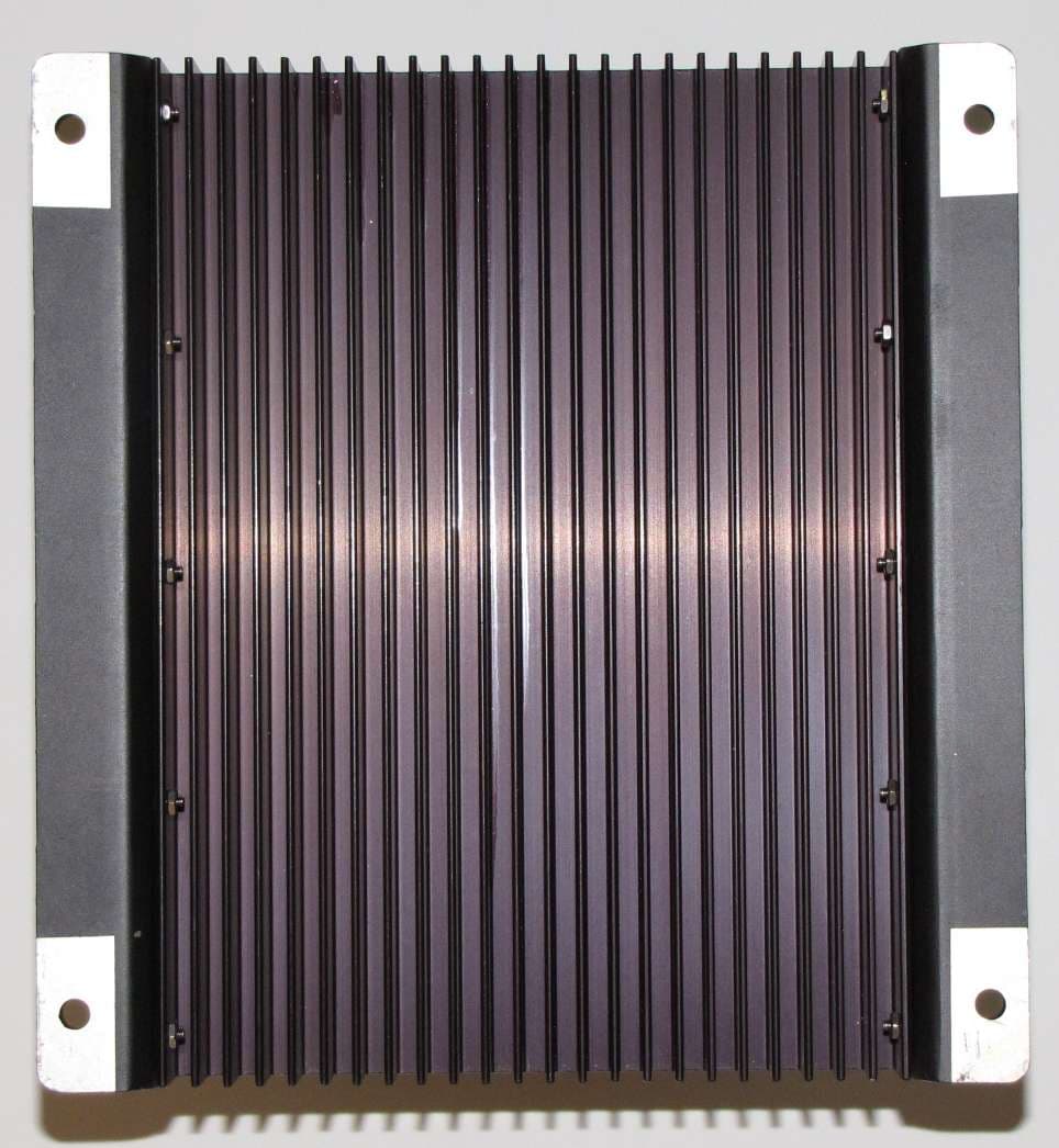
OV5PCSRAMP450A
Jun 28, 2010UHF 450 - 470 MHz RTK Amplifier
Equipment Class
AMP - Amplifier