OV5-PH85240000Radar Sensor
Deere & Company dba John Deere Intelligent Solutions Group
Click to zoom
Application Details
- Equipment Class
- FDS - Part 15 Field Disturbance Sensor
- Date of Grant
- Jun 11, 2026
- Application Purpose
- Original Equipment
- Equipment Note
- Radar Sensor
- Frequency Range
- 24127.00000000 - 24127.00000000
- Country
- United States
Documents & Files
Document Text
Text extracted from the exhibit documents filed with the FCC. Open a document above to read the original.
Users Manual
Company Use Radar Sensor User Information Radar Sensor, NA – PH85241632 Radar Sensor, C&F – PH85241196 Company Use Recognize Safety Information This is a safety-alert symbol. When you see this symbol on your machine or in this manual, be alert to the potential for personal injury. Follow recommended precautions and safe operating practices. Understand Signal Words DANGER; The signal word DANGER indicates a hazardous situation which, if not avoided, will result in death or serious injury. WARNING; The signal word WARNING indicates a hazardous situation which, if not avoided, could result in death or serious injury. CAUTION; The signal word CAUTION indicates a hazardous situation which, if not avoided, could result in minor or moderate injury. CAUTION may also be used to alert against unsafe practices associated with events which could lead to personal injury. A signal word—DANGER, WARNING, or CAUTION—is used with the safety-alert symbol. DANGER identifies the most serious hazards. DANGER or WARNING safety signs are located near specific hazards. General precautions are listed on CAUTION safety signs. CAUTION also calls attention to safety messages in this manual. Follow Safety Instructions Carefully read all safety messages in this instruction. Read the product operators manual for operating instructions and safety messages. Do not let anyone operate without instruction. (A copy of the operator’s manual may also be available from the Service ADVISOR™ application.) Replace Safety Signs Replace missing or damaged safety signs. See the machine operator’s manual for correct safety sign placement. Company Use Practice Safe Maintenance Understand service procedure before doing work. Keep area clean and dry. Never lubricate, service, or adjust machine while it is moving. Keep hands, feet, and clothing away from power-driven parts. Disengage all power and operate controls to relieve pressure. Lower equipment to the ground. Stop the engine. Remove the key. Allow machine to cool. Securely support any machine elements that must be raised for service work. Keep all parts in good condition and properly installed. Fix damage immediately. Replace worn or broken parts. Remove any buildup of grease, oil, or debris. On self-propelled equipment, disconnect battery ground cable (-) before making adjustments on electrical systems or welding on machine. On towed implements, disconnect wiring harnesses from tractor before servicing electrical system components or welding on machine. Falling while cleaning or working at height can cause serious injury. Use a ladder or platform to easily reach each location. Use sturdy and secure footholds and handholds. Use Steps and Handholds Correctly Prevent falls by facing the machine when getting on and off. Maintain 3-point contact with steps, handholds, and handrails. Use extra care when mud, snow, or moisture present slippery conditions. Keep steps clean and free of grease or oil. Never jump when exiting machine. Never mount or dismount a moving machine. Handle Electronic Components and Brackets Safely Falling while installing or removing electronic components mounted on equipment can cause serious injury. Use a ladder or platform to easily reach each mounting location. Use sturdy and secure footholds and handholds. Do not install or remove components in wet or icy conditions. If installing or servicing a RTK base station on a tower or other tall structure, use a certified climber. If installing or servicing a global positioning receiver mast used on an implement, use proper lifting techniques and wear proper protective equipment. The mast is heavy and can be awkward to handle. Two people are required when mounting locations are not accessible from the ground or from a service platform. Company Use Electrical System — General Instructions on Safety CAUTION: Before working on the electrical system, always disconnect battery ground cable (-). NOTE: Refer also to the Technical Manual before installing, removing or adjusting components. Use Technical Manuals When performing the work described in this instruction, use relevant Technical Manuals for additional service instruction. Carefully read and comply with safety messages and cautions presented throughout the text. Both diagnostic and repair technical manuals are concise guides for specific equipment. They are on-the-job instructions containing vital information to diagnose, analyze, test, and repair the equipment. Use Proper Tools Use tools appropriate to the work. Makeshift tools and procedures can create safety hazards. Use power tools only to loosen threaded parts and fasteners. For loosening and tightening hardware, use the correct size tools. DO NOT use U.S. measurement tools on metric fasteners. Avoid bodily injury caused by slipping wrenches. Use only service parts meeting John Deere specifications. Company Use Hardware Figure 1 – Radar Sensor Company Use Product Label Identify Date Code Radar Sensor Use the Date code (A) on the product label to identify the date of manufacture (DOM) A – Date Code Product Label Example A Company Use How to Use 1. Secure the Radar Sensor in a Deere designated location. The sensor will be secured with 8mm Cap Screw(s) using the provide hole(s) in the case. Figure 2 - Example of Mounting Point 2. Plug in the power/CAN harness into Radar Sensor. The Radar Sensor uses Delphi Metri-Pack 150 series (10-pin) connection. Figure 3 - Example of Harness Connector 3. The sensor end of the power/CAN harness shall connect to the CAN Bus on the John Deere Tractor. 4. Once the radar sensor is connected, the Display (Gen 4/Gen 5) can be powered on and reviewed for setup success Company Use Regulatory Statements United States – FCC Information This device must be operated as supplied by John Deere Ag Management Solutions. Any changes or modifications made to this device without the express written approval of John Deere Ag Management Solutions may void the user’s authority to operate this device. Th…
Text truncated - open the document above for the full version.
Attestation Statements
Rev 1/26/2023 Confidential with no Personal Information John Deere ISG-Urbandale 9505 NorthPark Dr, Urbandale, IA 50131 U.S.A Phone: 515-253-6921 E-mail: [email protected] Lane Arthur Vice President, Precision Technologies To: Federal Communications Commission Authorization and Evaluation Division 7435 Oakland Mills Road Columbia, MD 21046 USA Date: May 14, 2026 Ref: Attestation Statements Part 2.911(d)(7) Filing FCC ID: OV5-PH85240000 Deere & Company (“the applicant”) certifies that, as of the date of the filing of the application, Deere & Company, is our designated U.S. agent for the service of process for the above-referenced FCC ID. Deere & Company agrees to maintain an agent for no less than one year after the grantee has terminated all marketing and importation or the conclusion of any Commission-related proceeding involving the equipment. Deere & Company accepts, as of the date of the filing of the application, the obligation of the designated U.S. agent for service of process for the above-referenced FCC ID. Designated U.S. Agent Information: Name: Deere & Company Address: One Deere Place, Moline, IL, 61265 Contact Person: Lane Arthur Tel.: 515-253-6921 Email: [email protected] FRN: 0017417122 Sincerely, [Insert applicant name] Deere & Company (Applicant printed name) Mr. Lane Arthur (Applicant signature)
Attestation Statements
Confidential with no Personal Information Date: May 13, 2026 To: Federal Communications Commission Authorization and Evaluation Division 7435 Oakland Mills Road Columbia, MD 21046 USA Ref: Attestation Statements Part 2.911(d)(5)(i) and Part 2.911(d)(5)(ii) Filing Re. KDB 986446 D01 FCC ID: OV5-PH85240000 Dear Sir or Madam, Deere & Company (“the applicant”) certifies that the equipment for which authorization is sought is not “covered” equipment prohibited from receiving an equipment authorization under section 2.903 of the FCC rules. We also certify that, as of the application filing date, the applicant is not identified on the Covered List as an entity producing “covered” equipment. We further attest that the equipment for which authorization is sought does not contain, nor will it ever contain, integrated Kaspersky cybersecurity and/or anti-virus software produced by Kaspersky Lab Inc. or any of its successors and assignees. If you have any questions, please contact us. Sincerely, Paulo Ramos Manufacturer name: Deere & Company One John Deere Place, Moline, IL, USA 61265 [email protected] +55 19 9963 01800
Cover Letter(s)
John Deere ISG-Urbandale 9505 NorthPark Dr, Urbandale, IA 50131 U.S.A Phone: 515-253-6921 E-mail: [email protected] Lane Arthur Vice President, Precision Technologies March 18, 2026 TUV SUD America Inc. 10 Centennial Drive Peabody, MA 01960, USA Dear Sir or Madam, We, Deere & Company, hereby authorize Anes Dahmane of TUV SUD America, 5945 Cabot Parkway, Suite 100, Alpharetta GA 30005, to act as our agent in all matters relating to applications for equipment authorization, including the signing of all documents relating to these matters. Yours sincerely, Name: Lane Arthur Title: Vice President, Precision Technologies
Cover Letter(s)
- May 13, 2026 Federal Communications Commission Equipment Authorization Branch 7435 Oakland Mills Road Columbia, MD 21046 Confidentiality Request FCC ID: OV5-PH85240000 Pursuant to Sections 0.457(d)(1)(ii) and 0.459 of the Commission’s Rules, Deere & Company hereby requests permanent confidential treatment of information accompanying this application as outlined below: Schematics Bill of Materials/Parts List Block Diagrams Theory of Operation The above materials contain trade secrets and proprietary information not customarily released to the public. The public disclosure of these matters might be harmful to the Applicant and provide unjustified benefits to its competitors. The Applicant understands that pursuant to Rule 0.457(d)(1)(ii), disclosure of this Application and all accompanying materials will not be made before the date of the Grant for this Application. Yours sincerely, Name: Paulo Ramos Title: Sr. Product Safety Standards Engineer Paulo Ramos Manufacturer name: Deere & Company Sr. Product Safety Standards Engineer [email protected] +55 19 9963 01800
External Photos
Figure 1: Top View Figure 2: Side 1 View Figure 3: Side 2 View Figure 4: Side 3 View Figure 5: Side 4 View Figure 6: Bottom View
External Photos
Figure 1: Top View Figure 2: Side 1 View Figure 3: Side 2 View Figure 4: Side 3 View Figure 5: Side 4 View Figure 6: Bottom View
ID Label/Location Info
Figure 1: Sample Label and Location Figure 2: Sample HVIN Label and Location Figure 3: Sample HVIN Label and Location
Internal Photos
Figure 1: PH85241632 PCB Top Figure 2: PH85241632 PCB Bottom Figure 3: PH85241196 PCB Top Figure 4: PH85241196 PCB Bottom
RF Exposure Info
TÜV SÜD AMERICA INC 10040 Mesa Rim Road San Diego, CA 92121-2912 Phone: 858 678 1400 FAX: 858 546 0364 May 06, 2026 TUV SUD America CB 10 Centennial Drive FL2 Peabody, MA 01960 Attention: Director of Certification RE: Analysis of RF Exposure for Portable and Mobile use per KDB 447498 D01 Mobile Portable RF Exposure v06 and RSS-102 Issue 6 December 2023. FCC ID: OV5-PH85240000 IC: 11137A-PH85240000 Model: PH85241196 1. Limits: Limits for General Population/Uncontrolled Exposure (Title 47 Subpart J §2.1091 and KDB 447498 D01 referring to limits under §1.1310) Frequency Range (MHz) Electric Field Strength (E) (V/m) Magnetic Field Strength (H) (A/m) Power Density (S) (mW/cm 2 ) Averaging Time (minutes) 0.3 - 1.34 614 1.63 *(100) 30 1.34 - 30 824/f 2.19/f *(180/f 2 ) 30 30 - 300 27.5 0.073 0.2 30 300 - 1500 - - f/1500 30 1500 - 100,000 - - 1.0 30 f = frequency in MHz *Plane-wave equivalent power density Limits for Devices Used by the General Public (Uncontrolled Environment (RSS-102 Issue 6 December 2023) Frequency Range (MHz) Electric Field Strength (V/m rms) Magnetic Field (A/m rms) Power Density (W/m 2 ) Reference Period (minutes) 0.003 - 10 21 83 90 - Instantaneous* 0.1 - 10 - 0.73/f - 6** 1.1 - 10 87/f 0.5 - - 6** 10 - 20 27.46 0.0728 2 6 20 - 48 -58.07/f 0.25 0.1540/f 0.25 8.944/f 0.5 6 48 - 300 22.06 0.05852 1.291 6 300 - 6000 3.142 f 0.3417 0.008335 f .0.3417 0.02619 f 0.6834 6 6000 - 15000 61.4 0.163 10 6 15000 - 150000 61.4 0.163 10 616000/f 1.2 150000 - 300000 0.158f 0.5 4.21 x 10 .-4 f 0.5 6.67 x 10 .-5 f 616000/f 1.2 f is frequency in MHz *Based on nerve stimulation (NS) ** Based on specific absorption rate (SAR) TÜV SÜD AMERICA INC 10040 Mesa Rim Road San Diego, CA 92121-2912 Phone: 858 678 1400 FAX: 858 546 0364 2. Mobile MPE Calculation Summary using a 20cm separation distance: Mode (Worst Case) Radiated Field Strength (dBμV/m) Peak Power E.I.R.P (dBm) Power Density (mW/cm 2 ) 24 GHz Band Radar Frequency 122.04 26.81 0.09544 3. Mobile MPE Calculation using a 20cm separation distance: Using Power Density formula: S= PG 4πR 2 where: S = power density P = power input to the antenna G = power gain of the antenna in the direction of interest relative to isotropic R = distance to the center of radiation of the antenna Maximum peak output power at antenna input terminal: 26.81 (dBm) Maximum peak output power at antenna input terminal: 479.73 (mW) Antenna gain(typical): 0 (dBi) Maximum antenna gain: 1 (numeric) Prediction distance: 20 (cm) Source Based Time Average Duty Cycle: 100 (%) Prediction frequency: 24.135 (GHz) FCC MPE limit for uncontrolled exposure at prediction frequency: 1.000 (mW/cm 2 ) ISED MPE limit for uncontrolled exposure at prediction frequency: 10.0 (W/m 2 ) Power density at prediction frequency: 0.09544 (mW/cm 2 ) Power density at prediction frequency: 0.954 (W/m 2 ) FCC Margin of Compliance: -10.20 (dB) ISED Margin of Compliance: -50.20 (dB) Sincerely, Ferdie S. Custodio Name Authorized Signatory Title: Senior EMC Test Engineer /Wireless Team Lead
RF Exposure Info
TÜV SÜD AMERICA INC 10040 Mesa Rim Road San Diego, CA 92121-2912 Phone: 858 678 1400 FAX: 858 546 0364 May 06, 2026 TUV SUD America CB 10 Centennial Drive FL2 Peabody, MA 01960 Attention: Director of Certification RE: Analysis of RF Exposure for Portable and Mobile use per KDB 447498 D01 Mobile Portable RF Exposure v06 and RSS-102 Issue 6 December 2023. FCC ID: OV5-PH85240000 IC: 11137A-PH85240000 Model: PH85241632 1. Limits: Limits for General Population/Uncontrolled Exposure (Title 47 Subpart J §2.1091 and KDB 447498 D01 referring to limits under §1.1310) Frequency Range (MHz) Electric Field Strength (E) (V/m) Magnetic Field Strength (H) (A/m) Power Density (S) (mW/cm 2 ) Averaging Time (minutes) 0.3 - 1.34 614 1.63 *(100) 30 1.34 - 30 824/f 2.19/f *(180/f 2 ) 30 30 - 300 27.5 0.073 0.2 30 300 - 1500 - - f/1500 30 1500 - 100,000 - - 1.0 30 f = frequency in MHz *Plane-wave equivalent power density Limits for Devices Used by the General Public (Uncontrolled Environment (RSS-102 Issue 6 December 2023). Frequency Range (MHz) Electric Field Strength (V/m rms) Magnetic Field (A/m rms) Power Density (W/m 2 ) Reference Period (minutes) 0.003 - 10 21 83 90 - Instantaneous* 0.1 - 10 - 0.73/f - 6** 1.1 - 10 87/f 0.5 - - 6** 10 - 20 27.46 0.0728 2 6 20 - 48 -58.07/f 0.25 0.1540/f 0.25 8.944/f 0.5 6 48 - 300 22.06 0.05852 1.291 6 300 - 6000 3.142 f 0.3417 0.008335 f .0.3417 0.02619 f 0.6834 6 6000 - 15000 61.4 0.163 10 6 15000 - 150000 61.4 0.163 10 616000/f 1.2 150000 - 300000 0.158f 0.5 4.21 x 10 .-4 f 0.5 6.67 x 10 .-5 f 616000/f 1.2 f is frequency in MHz *Based on nerve stimulation (NS) ** Based on specific absorption rate (SAR) TÜV SÜD AMERICA INC 10040 Mesa Rim Road San Diego, CA 92121-2912 Phone: 858 678 1400 FAX: 858 546 0364 2. Mobile MPE Calculation Summary using a 20cm separation distance: Mode (Worst Case) Radiated Field Strength (dBμV/m) Peak Power E.I.R.P (dBm) Power Density (mW/cm 2 ) 24 GHz Band Radar Frequency 121.96 26.73 0.09370 3. Mobile MPE Calculation using a 20cm separation distance: Using Power Density formula: S= PG 4πR 2 where: S = power density P = power input to the antenna G = power gain of the antenna in the direction of interest relative to isotropic R = distance to the center of radiation of the antenna Maximum peak output power at antenna input terminal: 26.73 (dBm) Maximum peak output power at antenna input terminal: 470.98 (mW) Antenna gain(typical): 0 (dBi) Maximum antenna gain: 1 (numeric) Prediction distance: 20 (cm) Source Based Time Average Duty Cycle: 100 (%) Prediction frequency: 24.127 (GHz) FCC MPE limit for uncontrolled exposure at prediction frequency: 1.000 (mW/cm 2 ) ISED MPE limit for uncontrolled exposure at prediction frequency: 10.000 (W/m 2 ) Power density at prediction frequency: 0.09370 (mW/cm 2 ) Power density at prediction frequency: 0.937 (W/m 2 ) FCC Margin of Compliance: -10.28 (dB) ISED Margin of Compliance: -50.28 (dB) Sincerely, Ferdie S. Custodio Name Authorized Signatory Title: Senior EMC Test Engineer /Wireless Team Lead
Test Report
TÜV SÜD America, Inc. 10040 Mesa Rim Road San Diego, CA 92121-2912 TÜV SÜD America, Inc. Rancho Bernardo Facility 16936 Via Del Campo San Diego, CA 92127 Phone: 858 678 1400 www.tuv-sud-america.com TÜV SÜD RESPONSIBLE FOR NAME DATE SIGNATURE Authorized Signatory Ferdinand S. Custodio 05/01/26 Signatures in this approval box have checked this document in line with the requirements of TÜV SÜD document control rules. EXECUTIVE SUMMARY A sample of this product was tested and found to be in compliance with FCC Part 15 Subpart C §15.245 and ISED RSS-210 Issue 11 June 2024. Radio Testing of the John Deere Intelligent Solution Group Sensor, Eagle Radar Model: PH85241196 In accordance with FCC Part 15 Subpart C §15.245 and ISED RSS-210 Issue 11 June 2024 Prepared for: John Deere Intelligent Solution Group 9505 Northpark Dr. Urbandale, Iowa 50131 USA COMMERCIAL-IN-CONFIDENCE Date: May 2026 Document Number: 72171241B Issue 01 | Version Number: 01 A2LA Cert. No. 2955.13 DISCLAIMER AND COPYRIGHT This report has been prepared by TÜV SÜD America with all reasonable skill and care. The document is confidential to the potential Client and TÜV SÜD America. No part of this document may be reproduced without the prior written approval of TÜV SÜD America. ACCREDITATION Our A2LA Accreditation does not cover opinions and interpretations and any expressed are outside the scope of our A2LA Accreditation. FCC ID: OV5-PH85240000 IC: 11137A-PH85240000 Report No. 72171241B COMMERCIAL-IN-CONFIDENCE Page 2 of 41 REPORT ON TEST REPORT NUMBER TEST REPORT DATE Radio Testing of the John Deere Intelligent Solution Group Sensor, Eagle Radar Model PH85241196 72171241B May 2026 PREPARED FOR John Deere Intelligent Solution Group 9505 Northpark Dr. Urbandale, Iowa 50131 USA CONTACT PERSON Jessica Berberich Sr. Standards Engineer [email protected] (515) 253-6337 PREPARED BY Joe Salvador Name Authorized Signatory Title: Wireless/RF Test Engineer APPROVED BY Ferdinand S. Custodio Name Authorized Signatory Title: Senior EMC Test Engineer / Wireless Team Lead DATED 05/01/26 FCC ID: OV5-PH85240000 IC: 11137A-PH85240000 Report No. 72171241B COMMERCIAL-IN-CONFIDENCE Page 3 of 41 Revision History 72171241B John Deere Intelligent Solution Group Sensor, Eagle Radar Model PH85241196 DATE OLD REVISION NEW REVISION REASON PAGES AFFECTED APPROVED BY 05/01/26 Initial Release Ferdinand Custodio FCC ID: OV5-PH85240000 IC: 11137A-PH85240000 Report No. 72171241B COMMERCIAL-IN-CONFIDENCE Page 4 of 41 CONTENTS REPORT SUMMARY ................................................................................................................ 5 1.1 Introduction ................................................................................................................................ 6 1.2 Brief Summary Of Results ......................................................................................................... 7 1.3 Product Information ................................................................................................................... 8 1.4 EUT Test Configuration ............................................................................................................. 8 1.5 Deviations From The Standard ................................................................................................ 10 1.6 Modification Record ................................................................................................................. 10 1.7 Test Methodology .................................................................................................................... 10 1.8 Test Facility Location ............................................................................................................... 10 1.9 Test Facility Registration ......................................................................................................... 10 TEST DETAILS ....................................................................................................................... 12 2.1 RF Power Output ..................................................................................................................... 13 2.2 Spurious Emissions ................................................................................................................. 16 2.3 99% Emission Bandwidth ........................................................................................................ 28 TEST EQUIPMENT USED ...................................................................................................... 30 3.2 Measurement Uncertainty ........................................................................................................ 33 DIAGRAM OF TEST SETUP................................................................................................... 36 4.1 Test Setup Diagram ................................................................................................................. 37 ACCREDITATION, DISCLAIMERS AND COPYRIGHT .......................................................... 40 5.1 Accreditation, Disclaimers and Copyright................................................................................. 41 FCC ID: OV5-PH85240000 IC: 11137A-PH85240000 Report No. 72171241B COMMERCIAL-IN-CONFIDENCE Page 5 of 41 SECTION 1 REPORT SUMMARY Radio Testing of the John Deere Intelligent Solution Group Sensor, Eagle Radar PH85241196 FCC ID: OV5-PH85240000 IC: 11137A-PH85240000 Report No. 72171241B COMMERCIAL-IN-CONFIDENCE Page 6 of 41 1.1 INTRODUCTION The information contained in this report is intended to show verification of the John Deere Intelligent Solution Group Sensor, Eagle Radar PH85241196 to the requirements of FCC Part 15 Subpart C §15.245 and ISED RSS-210 Issue 11 June 2024. Objective To perform Radio Testing to determine the Equipment Under Test's (EUT’s) compliance with the test specification, for the series of tests carried out. Manufacturer John Deere Intelligent Solution Group…
Text truncated - open the document above for the full version.
Test Report
TÜV SÜD America, Inc. 10040 Mesa Rim Road San Diego, CA 92121-2912 TÜV SÜD America, Inc. Rancho Bernardo Facility 16936 Via Del Campo San Diego, CA 92127 Phone: 858 678 1400 www.tuv-sud-america.com TÜV SÜD RESPONSIBLE FOR NAME DATE SIGNATURE Authorized Signatory Ferdinand S. Custodio 05/01/26 Signatures in this approval box have checked this document in line with the requirements of TÜV SÜD document control rules. EXECUTIVE SUMMARY A sample of this product was tested and found to be in compliance with FCC Part 15 Subpart C §15.245 and ISED RSS-210 Issue 11 June 2024. Radio Testing of the John Deere Intelligent Solution Group Sensor, Eagle Radar Model: PH85241632 In accordance with FCC Part 15 Subpart C §15.245 and ISED RSS-210 Issue 11 June 2024 Prepared for: John Deere Intelligent Solution Group 9505 Northpark Dr. Urbandale, Iowa 50131 USA COMMERCIAL-IN-CONFIDENCE Date: May 2026 Document Number: 72171241B Issue 01 | Version Number: 01 A2LA Cert. No. 2955.13 DISCLAIMER AND COPYRIGHT This report has been prepared by TÜV SÜD America with all reasonable skill and care. The document is confidential to the potential Client and TÜV SÜD America. No part of this document may be reproduced without the prior written approval of TÜV SÜD America. ACCREDITATION Our A2LA Accreditation does not cover opinions and interpretations and any expressed are outside the scope of our A2LA Accreditation. FCC ID: OV5-PH85240000 IC: 11137A-PH85240000 Report No. 72171241B COMMERCIAL-IN-CONFIDENCE Page 2 of 40 REPORT ON TEST REPORT NUMBER TEST REPORT DATE Radio Testing of the John Deere Intelligent Solution Group Sensor, Eagle Radar Model PH85241632 72171241B May 2026 PREPARED FOR John Deere Intelligent Solution Group 9505 Northpark Dr. Urbandale, Iowa 50131 USA CONTACT PERSON Jessica Berberich Sr. Standards Engineer [email protected] (515) 253-6337 PREPARED BY Joe Salvador Name Authorized Signatory Title: Wireless/RF Test Engineer APPROVED BY Ferdinand S. Custodio Name Authorized Signatory Title: Senior EMC Test Engineer / Wireless Team Lead DATED 05/01/26 FCC ID: OV5-PH85240000 IC: 11137A-PH85240000 Report No. 72171241B COMMERCIAL-IN-CONFIDENCE Page 3 of 40 Revision History 72171241B John Deere Intelligent Solution Group Sensor, Eagle Radar PH85241632 DATE OLD REVISION NEW REVISION REASON PAGES AFFECTED APPROVED BY 05/01/26 Initial Release Ferdinand Custodio FCC ID: OV5-PH85240000 IC: 11137A-PH85240000 Report No. 72171241B COMMERCIAL-IN-CONFIDENCE Page 4 of 40 CONTENTS REPORT SUMMARY ................................................................................................................ 5 1.1 Introduction ................................................................................................................................ 6 1.2 Brief Summary Of Results ......................................................................................................... 7 1.3 Product Information ................................................................................................................... 8 1.4 EUT Test Configuration ............................................................................................................. 8 1.5 Deviations From The Standard ................................................................................................ 10 1.6 Modification Record ................................................................................................................. 10 1.7 Test Methodology .................................................................................................................... 10 1.8 Test Facility Location ............................................................................................................... 10 1.9 Test Facility Registration ......................................................................................................... 10 TEST DETAILS ....................................................................................................................... 12 2.1 RF Power Output ..................................................................................................................... 13 2.2 Spurious Emissions ................................................................................................................. 16 2.3 99% Emission Bandwidth ........................................................................................................ 27 TEST EQUIPMENT USED ...................................................................................................... 29 3.2 Measurement Uncertainty ........................................................................................................ 32 DIAGRAM OF TEST SETUP................................................................................................... 35 4.1 Test Setup Diagram ................................................................................................................. 36 ACCREDITATION, DISCLAIMERS AND COPYRIGHT .......................................................... 39 5.1 Accreditation, Disclaimers and Copyright................................................................................. 40 FCC ID: OV5-PH85240000 IC: 11137A-PH85240000 Report No. 72171241B COMMERCIAL-IN-CONFIDENCE Page 5 of 40 SECTION 1 REPORT SUMMARY Radio Testing of the John Deere Intelligent Solution Group Sensor, Eagle Radar PH85241632 FCC ID: OV5-PH85240000 IC: 11137A-PH85240000 Report No. 72171241B COMMERCIAL-IN-CONFIDENCE Page 6 of 40 1.1 INTRODUCTION The information contained in this report is intended to show verification of the John Deere Intelligent Solution Group Sensor, Eagle Radar PH85241632 to the requirements of FCC Part 15 Subpart C §15.245 and ISED RSS-210 Issue 11 June 2024. Objective To perform Radio Testing to determine the Equipment Under Test's (EUT’s) compliance with the test specification, for the series of tests carried out. Manufacturer John Deere Intelligent Solution Group EUT S…
Text truncated - open the document above for the full version.
Test Setup Photos
FCC ID: OV5-PH85240000 IC: 11137A-PH85240000 Radiated Emissions Test Setup (below 30MHz) *Margin observed at this range is >40dB, the use of an alternative Test Site is justified. Radiated Emissions Test Setup (30MHz to 1GHz) Radiated Emissions Test Setup (1GHz to 18GHz) Radiated Emissions Test Setup (18GHz to 26GHz) Radiated Emissions Test Setup (26GHz to 40GHz) Radiated Emissions Test Setup (above 40GHz)
Contact Information
Applicant
Lane Arthur(Vice President, Embedded Solutions)
[email protected]Fax: 515-331-4705
Technical Contact
Deere & CompanyLane Arthur
One John Deere Place · Moline, Illinois, 61265 · United States
Test Firm
TUV SUD America Inc.Mac Elliott
[email protected]Fax: 978 977 0182
Technical Specifications
| # | Rule Parts | Frequency Range | Power Output |
|---|---|---|---|
| 1 | 15.245 | 24.13 GHz - 24.13 GHz | 471.00 mW |
| 2 | 15.245 | 24.13 GHz - 24.13 GHz | 480.00 mW |
Other Applications from Deere & Company dba John Deere Intelligent Solutions Group

OV5-MA4R
Jun 01, 2022Telematics Modem
Equipment Class
DTS - Digital Transmission System
OV5-WDSB
Aug 03, 2020Wireless Data Server
Equipment Class
DTS - Digital Transmission System
OV5-RTK450
Apr 21, 2020RTK Radio
Equipment Class
TNB - Licensed Non-Broadcast Station Transmitter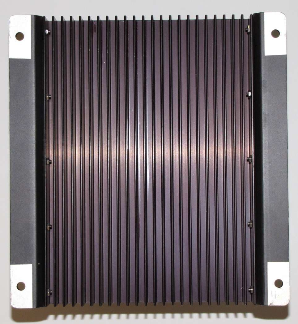
OV5PCSRAMP450A
Jun 28, 2010UHF 450 - 470 MHz RTK Amplifier
Equipment Class
AMP - Amplifier
OV5-PF80452
Apr 23, 2002JDLINK Machine Messenger
Equipment Class
TNB - Licensed Non-Broadcast Station Transmitter