OW5BST1901external radio frequency power amplifier (erfpa)
Mobile Communications Technologies Inc.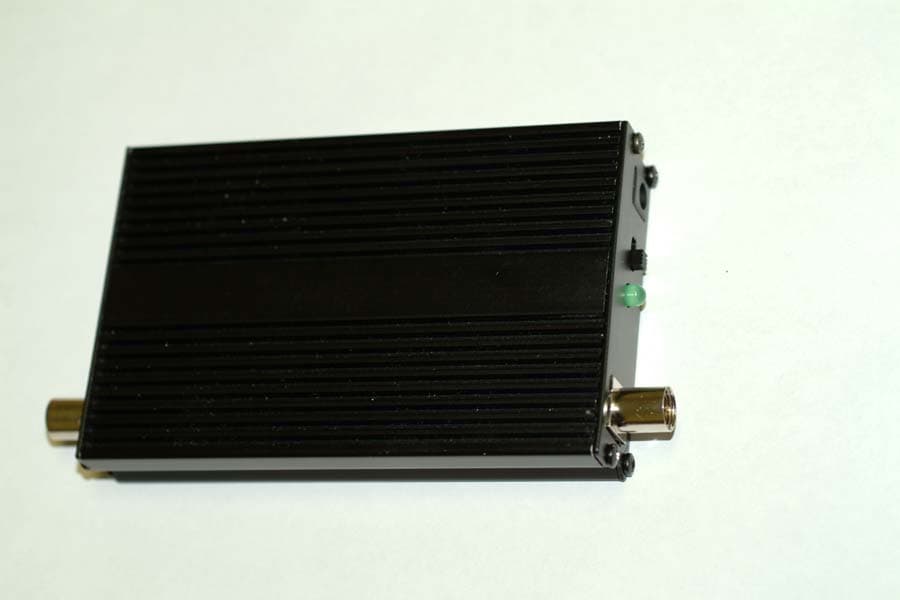
Click to zoom
Application Details
- Equipment Class
- AMP - Amplifier
- Date of Grant
- May 09, 2004
- Application Purpose
- Original Equipment
- Date of Application
- May 09, 2004
- Equipment Note
- external radio frequency power amplifier (erfpa)
- Frequency Range
- 1851.25000000 - 1908.75000000
- Country
- Canada
Documents & Files
Document Text
Text extracted from the exhibit documents filed with the FCC. Open a document above to read the original.
Cover Letter(s)
360 Industrial Pkwy South Unit#1&2 Aurora, Ont. Canada L4G 3V7 Phone:(905)726-3444 Fax:(905)726-4233 Email [email protected] April 23/04. Timco Engineering 849 NW State Road 45 Newberry, Florida 32669 888.472.2424 F 352.472.2030 To Whom It May Concern: The following information is to be held confidential pursuant of 47 CFR Part 0 §0.459 and Section 552(b)(4) of the Freedom of Information Act, because the information provided contains trade secrets and is proprietary. If made public, the information might be used to the disadvantage of the applicant in the market place. • Schematics • Block Diagram • Parts List • Operational Description Sincerely, Tom Vagenas Director
Cover Letter(s)
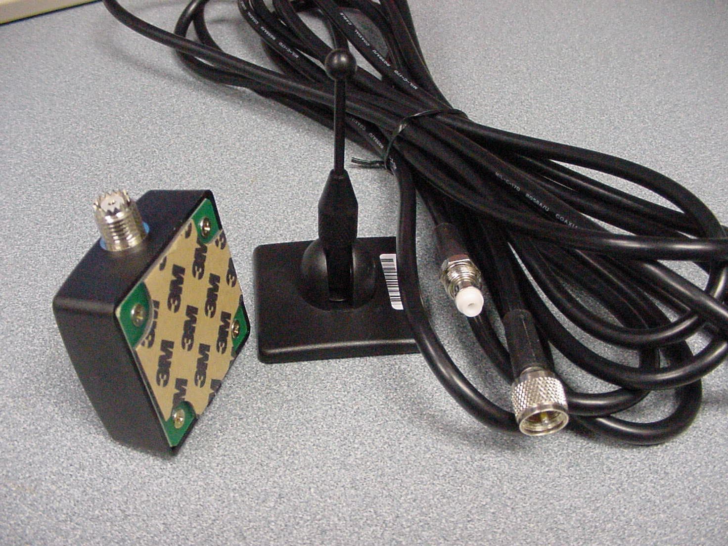
Reply to OET RT #12545 1/ Please describe and/or demonstrate compliance with 24.232(b) 2W EIRP. The device is comprised of an external radio frequency power amplifier with a maximum output power of 2W in the PCS band, a coaxial cable RG58 of at least 15 feet with a loss of at least 4dB at 1.9GHz, and antennas with a gain of less than 3dBi. This device does not exceed the maximum 2W EIRP of Part 24.232(b) according to the data and accessories marketed with this amplifier. The maximum antenna gain and cable loss chosen for the calculations overestimate the maximum EIRP, as found for such applications. Typical antenna, of the type listed in the user’s manual, 15” dual band magnet or glass mount, do not exceed a gain of 3dBi. They would yield a 3 dBi gain if mounted with a perfect ground. However, they are used in applications where the measurement should be made in free space in the case of glass mount and with an imperfect ground plane for magnet mount. The actual rating for such antenna installed on the roof of a vehicle or a window is lower than 3dBi. 2/ The grant note and RF exposure exhibit were revised.
RF Exposure Info
RF exposure exhibit FCC RF Exposure Requirements General information: FCCID: OW5BST1900 Modulation: CDMA Device category: Mobile / Part 2.1091 Environment: General Population/Uncontrolled Exposure Mobile devices that operate in the Personal Communication Service authorized under subpart H of part 22 and subpart E of part 24 are subject to routine environmental evaluation for RF exposure prior to equipment authorization or use if they operate at frequencies of 1.5 GHz or below and their effective radiated power (ERP) is 1.5 watts (2.46WEIRP) or more, or if they operate at frequencies above 1.5 GHz and their ERP is 3 watts (4.92WEIRP) or more. Otherwise, compliance with the power density limits of 1.1310 is required. Mobile devices under part 24.232(b) must not exceed 2W EIRP. Antenna: The manufacturer specifies antennas to be used with this device as documented in the user’s manual. This device has provisions for operation in a vehicle. Configuration Antenna p/n Type Max. Gain (dBi) Passenger car - Dual band omni 3 Operating configuration and exposure conditions: The conducted output power is 33dBm = 2 Watt The maximum antenna gain and cable loss chosen for the calculations overestimate the maximum EIRP, as found for such applications. Typical antenna, of the type listed in the user’s manual, 15” dual band magnet or glass mount, do not exceed a gain of 3dBi. They would yield a 3 dBi gain if mounted with a perfect ground. However, they are used in applications where the measurement should be made in free space in the case of glass mount and with an imperfect ground plane for 7/1/2004 Page 1 of 2 FCCID: RFJCB-127 magnet mount. The actual rating for such antenna installed on the roof of a vehicle or a window is lower than 3dBi. Vehicle Operation: The maximum antenna gain used for the calculation is 3dBi. A coaxial cable of the type RG174/58 has a loss of at least 3dB/4.5dB at 1880MHz for a length of 10\15feet. For such configuration the maximum EIRP is less than 2Watt. MPE Calculation: The minimum separation distance is calculated as follows: The limit for general population/uncontrolled exposure environment is 1mW/cm2 above 1500MHz. Channel Frequency: 1880MHz Max. Antenna Gain (dBi) / Minimum Cable Loss (dB) Power Density at 20 cm distance 3dBi / 3dB - - Freq (MHz) Power EIRP (W) Duty Cycle (%) (mW/cm 2 ) (mW/cm 2 ) (mW/cm 2 ) - - 100 (CDMA) - - - 1880 2 100 (CDMA) 0.4 - - Conclusion: The device complies with the MPE requirements by providing a safe separation distance of 20 cm between the antenna, including any radiating structure, and any persons when normally operated . 7/1/2004 Page 2 of 2 FCCID: RFJCB-127
Test Report
TIMCO ENGINEERING INC. 849 NW State Road 45 Newberry, Florida 32669 http://www.timcoengr.com 888.472.2424 F 352.472.2030 email: [email protected] APPLICANT: Mobile Communications Technologies Inc. FCC Test Report Product Name: CDMA1900 SN: 75984 EXTERNAL RADIO FREQUENCY POWER AMPLIFIER (ERFPA) FCC ID: OW5BST1901 Applicant: Mobile Communications Technologies Inc. 360 Industrial Parkway South Unit 1 Aurora Ontario L4G 3V7 Canada Date Receipt: MARCH 29, 2004 Date Tested: APRIL 23, 2004 PLEASE NOTE: THE ATTACHED REPORT SHALL NOT BE REPRODUCED EXCEPT IN FULL WITHOUT THE WRITTEN APPROVAL OF TIMCO ENGINEERING, INC. FCC ID: OW5BST1901 REPORT #: M\Mobile_Comm_OW5\427AUT4\427AUT4TestReport.doc COVER SHEET TIMCO ENGINEERING INC. 849 NW State Road 45 Newberry, Florida 32669 http://www.timcoengr.com 888.472.2424 F 352.472.2030 email: [email protected] APPLICANT: Mobile Communications Technologies Inc. TABLE OF CONTENTS LIST TEST REPORT: PAGE 1............COMPLIANCE STATEMENT PAGE 2............GENERAL INFORMATION & TECHNICAL DESCRIPTION PAGE 3............TECHNICAL DESCRIPTION CONTINUED RF POWER OUTPUT PAGE 4-6..........CARRIER POWER CDMA2000 / CDMA1 PAGE 7-9..........OCCUPIED BANDWIDTH CDMA2000 / CMDA1 PAGE 10-11........INPUT/OUTPUT MODULATED AMPLITUDE COMPARISON CDMA2000 PAGE 12-13........INPUT/OUTPUT MODULATED AMPLITUDE COMPARISON CDMA1 PAGE 14-16........OUT OF BAND EMISSIONS & BANDEDGE COMPLIANCE CDMA2000 PAGE 17-19........OUT OF BAND EMISSIONS & BANDEDGE COMPLIANCE CDMA1 PAGE 20-24........SPURIOUS EMISSIONS AT ANTENNA TERMINALS CDMA2000 PAGE 25-29........SPURIOUS EMISSIONS AT ANTENNA TERMAINALS CDMA1 PAGE 30...........METHOD OF MEASURING SPURIOUS EMISSIONS AT ANTENNA TERMINALS PAGE 31...........FIELD STRENGTH OF SPURIOUS EMISSIONS METHOD OF MEASURING RADIATED SPURIOUS EMISSIONS PAGE 32-35........EQUIPMENT LIST EXHIBITS CONTAINING: CONFIDENTIALITY LETTER BLOCK DIAGRAM SCHEMATIC PARTS LIST USERS MANUAL LABEL SAMPLE LABEL LOCATION EXTERNAL PHOTOGRAPHS INTERNAL PHOTOGRAPHS TUNING PROCEDURE OPERATIONAL DESCRIPTION TEST SET UP PHOTOGRAPH RF EXPOSURE STATEMENT FCC ID: OW5BST1901 REPORT #: M\Mobile_Comm_OW5\427AUT4\427AUT4TestReport.doc TABLE OF CONTENTS TIMCO ENGINEERING INC. 849 NW State Road 45 Newberry, Florida 32669 http://www.timcoengr.com 888.472.2424 F 352.472.2030 email: [email protected] APPLICANT: Mobile Communications Technologies Inc. COMPLIANCE STATEMENT: This equipment has been tested in accordance with the standards identified in this test report. To the best of my knowledge and belief, these tests were performed using the measurement procedures described in this report and demonstrate that the equipment complies with the appropriate standards. No modifications were made to the equipment during testing in order to demonstrate compliance with these standards. I attest that the necessary measurements were made, under my supervision, at TIMCO ENGINEERING, INC. located at 849 N.W. State Road 45, Newberry, Florida 32669. Authorized Signatory Name: Bruno C. Clavier Signature: Date: 05/03/04 Test engineer name: Joe Scoglio Signature: Date: 04/27/04 FCC ID: OW5BST1901 REPORT #: M\Mobile_Comm_OW5\427AUT4\427AUT4TestReport.doc Page 1 of 35 TIMCO ENGINEERING INC. 849 NW State Road 45 Newberry, Florida 32669 http://www.timcoengr.com 888.472.2424 F 352.472.2030 email: [email protected] APPLICANT: Mobile Communications Technologies Inc. GENERAL INFORMATION REQUIRED FOR TYPE ACCEPTANCE 2.1033(c)(1)(2) Mobile Communications Technologies Inc. will manufacture the FCCID: OW5BST1901 EXTERNAL RF POWER AMPLIFIER in quantity, for use under FCC RULES PART 24. Mobile Communications Technologies Inc. 360 Industrial Parkway South Unit 1 Aurora, Ontario L4G 3V7 Canada 2.1033(c) TECHNICAL DESCRIPTION 2.1033(c)(3) Instruction book. A draft copy of the instruction manual is included in the exhibits. 2.1033(c) (4) Type of Emission: CDMA1900 was tested for two standards IS95 (2G) and CDMA2000 (3G). Reverse Link modulated signal was applied to the input "Phone" port of CDMA1900 1M25F9W (CDMA IS-95, CDMA1X, CDMA2000) 99 % Power bandwidth = 1.25 MHz Bn = 1.25 MHz Type of Emission: F9W (CDMA) 2.1033(c)(5) Frequency Range: 1850-1910 MHz 2.1033(c)(6) There are no user power controls. 2.1033(c)(7) Maximum input power rating +24 dBm (250 mW) RF POWER TO THE INPUT "PHONE" PORT OF DUT Maximum rated conducted output power is 2 Watt (33dBm) at the DUT output connector(antenna side) The device cannot operate in saturation because CDMA handsets which are attached to this device have a max ouput power of 24dbm. The DUT is directly connected to the handset by means of a cable which has 1.2dB loss. When CDMA handsets are at max output power of 24dBm the device remains linear within the CDMA standard for IS95, CDMA1X, CDMA2000 and WCDMA. 2.1033(c)(8) DC Voltages and Current into Final Amplifier: POWER INPUT: FINAL AMPLIFIER ONLY INPUT POWER – HIGH: (12V)(0.6A) = 7.2Watts FCC ID: OW5BST1901 REPORT #: M\Mobile_Comm_OW5\427AUT4\427AUT4TestReport.doc Page 2 of 35 TIMCO ENGINEERING INC. 849 NW State Road 45 Newberry, Florida 32669 http://www.timcoengr.com 888.472.2424 F 352.472.2030 email: [email protected] APPLICANT: Mobile Communications Technologies Inc. 2.1033(c)(9) Tune-up procedure. The tune-up procedure is included in the exhibits. 2.1033(c)(10) Complete Circuit Diagrams: The circuit diagram and block diagram are included in the exhibits. Description of all circuitry and devices provided for determining and stabilizing frequency is included in the exhibits. 2.1033(c)(11) A photograph or drawing of the equipment identification label is shown in the exhibits. 2.1033(c)(12) Photographs of the equipment of sufficient clarity to reveal equipment construction and layout and label location are shown in the exhibits. 2.1033(c)(13) For equipment employing digital modulation, a detail description of the modulation technique: N/A as this device is an amplifier 2.1033(c)(14) The data required for 2.1046 through 2.1057 is submitted below. 2.1046(a) …
Text truncated - open the document above for the full version.
Contact Information
Applicant
Tom Vagenas(Director Of Operations)
Test Firm
Timco Engineering, Inc.S Sanders
Technical Specifications
| # | Rule Parts | Frequency Range | Power Output | Emission | Tolerance |
|---|---|---|---|---|---|
| 1 | 24 | 1.85 GHz - 1.91 GHz | 2 W | F9W | Amp |
Other Applications from Mobile Communications Technologies Inc.
OW5BST850
Sep 21, 2003GSM/GPRS/TDMA/EDGE Cellular Band Amplifier
Equipment Class
AMP - Amplifier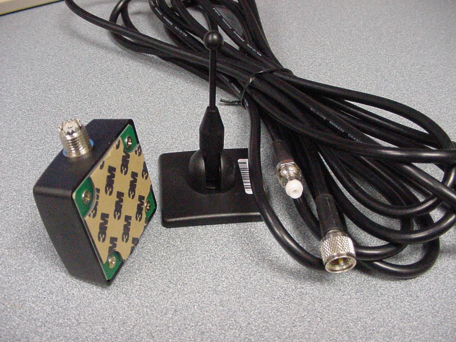
OW5BST1900
Jul 23, 2003GSM/GPRS PCS Band Amplifier
Equipment Class
AMP - Amplifier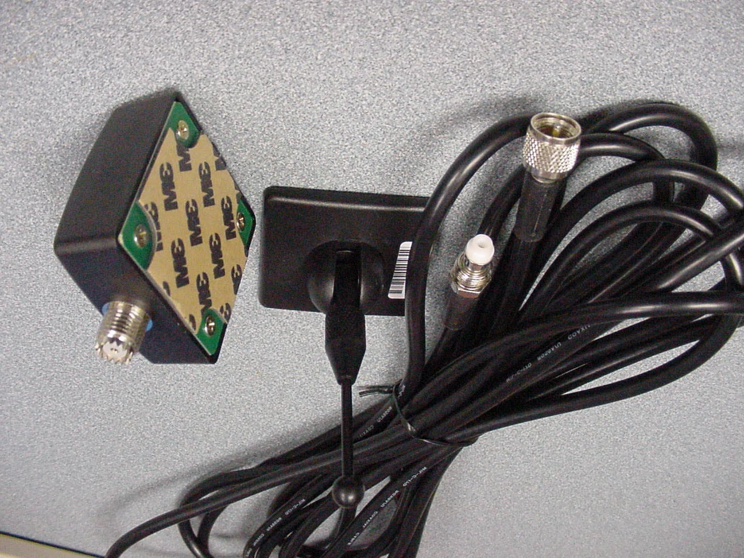
OW5BST801
Nov 20, 2002IDEN Booster/Amplifier (
Equipment Class
AMP - Amplifier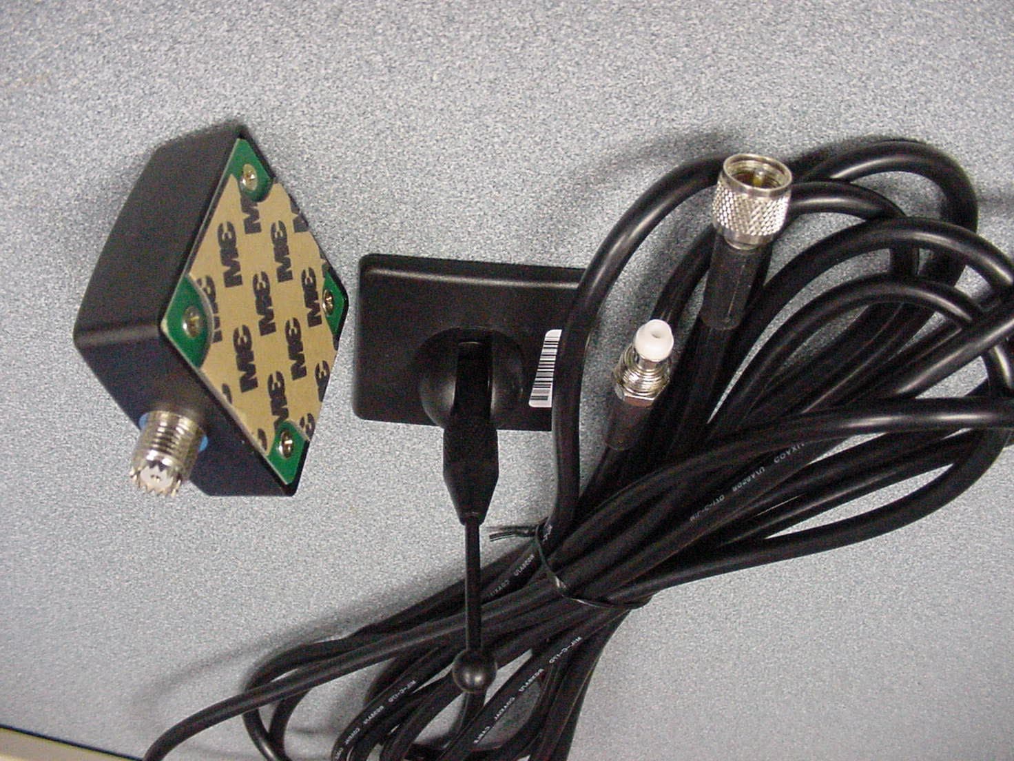
OW5BST800
Nov 13, 2002Mobile Cellular Band Subscriber Station Amplifier
Equipment Class
AMP - Amplifier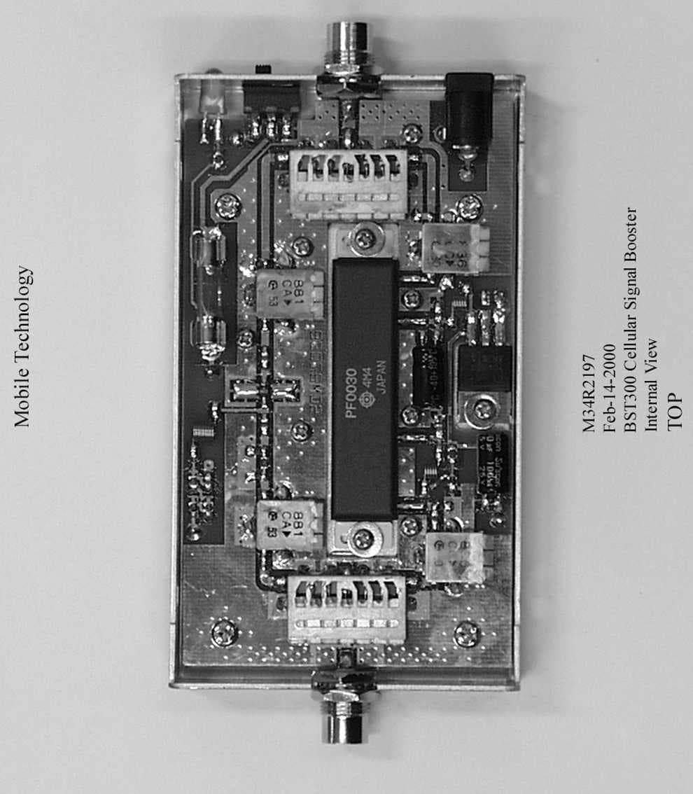
OW5BST300
Jun 27, 2001Mobile T.D.M.A Cellular Booster
Equipment Class
AMP - Amplifier