OW5BST800Mobile Cellular Band Subscriber Station Amplifier
Mobile Communications Technologies Inc.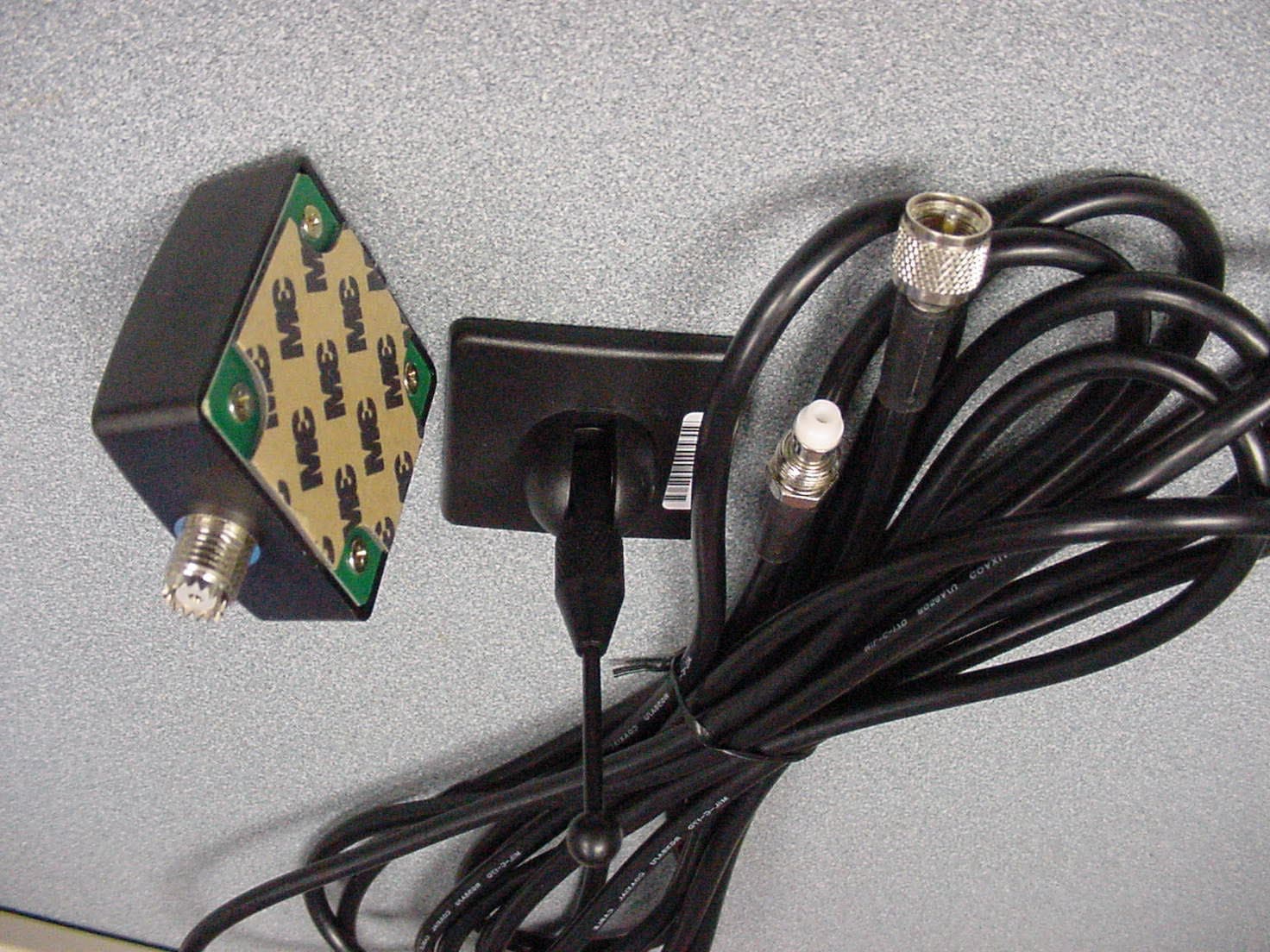
Click to zoom
Application Details
- Equipment Class
- AMP - Amplifier
- Date of Grant
- Nov 13, 2002
- Application Purpose
- Original Equipment
- Date of Application
- Nov 13, 2002
- Equipment Note
- Mobile Cellular Band Subscriber Station Amplifier
- Frequency Range
- 824.00000000 - 849.00000000
- Country
- Canada
Documents & Files
Document Text
Text extracted from the exhibit documents filed with the FCC. Open a document above to read the original.
Users Manual
User Instruction Manual Model BST800 Maximum Power Dual Band Glass Mount 15” Antenna AC/DC Power Supply (Optional)Allows Use of Booster In Home Or Office Adapter Cables (Order Separately) Specifications: Model:BST800 Frequency Range (Mhz) Antenna Gain Only Uplink 824-849 1850-1910 Downlink 869-894 1930-1990 Output Power max 3 Watt N/A Gain Antenna Gain Only Uplink +13dB 6dB max Downlink +13dB 6dB max DC Input Power Stand By DC 12V/0.2A Max In Use DC12V/1.6A Max RFConnector MCT-Male Weight 535g Dimensions 222 x 82 x 25mm Mobile Communication Technologies Inc. Contact Us On The Internet At www.smoothtalker.com SmoothTalker SmoothTalker MCT Dual Band Mag Mount Antenna Maximum Power Dual Band Glass Mag Antenna (Optional) Dual Band Glass Mount 4” Antenna Cellular Booster Amplifier CDMA IS95*CDMA1X*CDMA2000 WCDMA GSM with EDGE GPRS User Instructions Typical Car Installation Cellular Phone Hands Free In-car Kit Antenna Car Kit Ant Out Cellular Antenna Adapter Car Booster Car Antenna Car Booster Instructions: 1 ) Instructions for m **This device should be installed with the antenna supplied. It is required that the antenna is mounted is a suitable location which is a minimum distance of 20cm(8 inches)away from the user or nearby persons in order to comply with FCC rules concerning MPE (Maximum Permissible Exposure) safety limits** Magnetic Mount: Place centered, only on vehicle roof or 8 inches(20cm) away from any vehicle occupant or nearby persons. Glass mount: The antenna base should be placed on the front or rear windshield and centered as close to the vehicle roof as possible. It should be positioned to provide a minimum distance of 8 inches (20 cm) from any of the vehicle occupants or nearby persons. Run the co-ax cable along the head liner or along the floor under the carpet and bring up to the position of the booster. Connect co-ax cable to side of booster marked “Antenna”. Trunk mount: When mounting on trunk the antenna should be placed in the center of the trunk closest to the rear windshield of the vehicle. 3) Connect the 100cm cable from cell phone to side of booster marked “Signal Adapter”. When using with Cell Phone:connect cell phone adapter cable from cell phone to 100cm cable. When using with Car Kit: connect Car Kit antenna out, to 100cm cable. ) Place the Booster in a suitable location under the dashboard and plug in power cord to cigarette lighter socket of vehicle. 2ounting antenna to vehicle: It should be positioned to provide a minimum distance of 8 inches (20 cm) from any of the vehicle occupants or nearby persons. 4) Tighten all connections securely and move the switch located at the side of the booster to the “on” position. A green light will indicate that the unit is now ready for use. PLEASE NOTE: It is normal for the booster to be quite warm while the phone is in use. NOTE: This equipment has been tested and found to comply with the limits for a Class AB digital devices, pursuant to Part 22 of the FCC Rules. These limits are designed to provide reasonable protection against harmful interference in a residential installation. This equipment generates, uses, and can radiate radio frequency energy and, if not installed and used in accordance with the instruction manual, may cause harmful interference to radio communications. However, there is no guarantee that interference will not occur in a particular installation. If this equipment does cause harmful interference to radio or television reception, which can be determined by turning the equipment off and on, the user is encouraged to try to correct the interference by one of more of the following measures: Reorient or relocate the receiving antenna · Increase the separation between the equipment and receiver · Connect the equipment into an outlet on a circuit different from that to which the receiver is connected. · Consult the dealer or an experienced radio/TV technician for help. "Changes or modifications not expressly approved by MCT, Inc., the party responsible for compliance, could void the user's authority to operate the equipment." www.smoothtalker.com Must be centered on Roof , Windsheild or Trunk Antenna
Cover Letter(s)
American Telecommunications Certification Body Inc. 6731 Whittier Ave, McLean, VA 22101 November 12, 2002 RE: Mobile Communications Technologies, Inc. FCC ID: OW5BST800 I have a few comments on this Application. 1.) The device in question is a Part 22 AMPS band mobile Cellphone booster. Since most Part 22 800MHz band Cellular products utilize an analog AMPS-FM mode when roaming, it would be prudent to show how this device will operate under AMPS-FM conditions. Please include AMPS-FM data in the test report. Response : This does not apply as this device is for use with CDMA1 IS 95, CDMA1X, CDMA2000, WCDMA, and GSM with EDGE GPRS systems only. 2.) Maximum power for an 800MHz AMPS-FM product is usually ~600mW, while the minimum conducted power for a CDMA phone is typically -56dBm. Please provide a graph of input vs. output power from at minimum -56dBm to +28dBm input power. Please show where the 3dB compression point will occur. My concern is that excessive noise power in the system will limit or interfere with other users. Response : This does not apply as this device is for use with CDMA1 IS 95, CDMA1X, CDMA2000, WCDMA, and GSM with EDGE GPRS systems only. 3.) Please provide more detailed installation instructions so both bystanders and passengers will be limited in their RF Exposure by trunk, roof, and glass mount antennas. Response : Please refer to the revised installation instructions in the User Manual uploaded with this response. 4.) Labeling in manual is incorrect. Since this device is larger than the palm of the hand, the statement of 15.19(a)(1) should be shown on the exterior of the device. It should not appear in the manual. Response : The 15.19(a)(1) statement is not mandatory for this device however the client requests that this statement remain in the manual due to the growing number of automobiles with televisions. 5.) Information to user as specified in 15.21 is missing. Response : This statement has been added to the revised user manual that was uploaded with this response. 6.) Tune up procedures are missing. Response : Per the manufacturer, there is no tune up procedure for this device. 7.) Please provide power output readings for both input and output occupied bandwidth signals. Is channel power peak, average or something else? Response : Please refer to Section 6 of the revised test report, specifically Plots 6-2, 6-4 and 6-6, for the input and output levels and amplification. The channel power is peak, and is stated in the test report. 8.) Is Agilent communication analyzer listed in equipment list? If so indicate model, serial and calibration date. Response : A communication analyzer was not utilized for testing; a spectrum analyzer and a signal generator capable of measuring current-generation cellular modulation types were utilized, and these are included in the equipment list. 9.) Please show work in MPE Estimation located in RF Exposure Exhibit. Response : Please refer to the revised RF Exposure Exhibit uploaded with this response. William H. Graff President and Examining Engineer mailto: [email protected] The items indicated above must be submitted before processing can continue on the above referenced application. Failure to provide the requested information may result in application termination. Correspondence should be considered part of the permanent submission and may be viewed from the Internet after a Grant of Equipment Authorization is issued. Please do not respond to this correspondence using the email reply button. In order for your response to be processed expeditiously, you must submit your documents through the AmericanTCB.com website. Also, please note that partial responses increase processing time and should not be submitted. Any questions about the content of this correspondence should be directed to the sender.
Cover Letter(s)
American Telecommunications Certification Body Inc. 6731 Whittier Ave, McLean, VA 22101 November 14, 2002 RE: Mobile Communications Technologies, Inc. FCC ID: OW5BST800 I have additional comments on this Application. 1.) Your response to my request for information (1.) and (2.) in the November 12 application comments is unsatisfactory. This device appears to be designed for the “generic” 835MHz AMPS band Cellular market. It is not reasonable to assume that AMPS-FM will not be present, especially in fringe conditions where digital service has not yet been built out. My requests still stand. Response : Please see the plots uploaded with this response. 2.) Diagrams supplied for installation must be more explicit. Only the roof mount is addressed. Additional detail is required to assure MPE compliance for trunk and glass mount. Response : Please refer to the revised Installation Instructions uploaded with this response. 3.) Item (4.) from the November 12 comments – agreed. 4.) Tune-up procedure is a basic requirement of any device used in the Licensed services per Part 2 of the Rules. Please provide an appropriate exhibit. Response : Please refer to the Tune Up Procedure letter uploaded with this response. 5.) With regard to the RF Exposure Report, the maximum antenna gain listed is a 2.6dBi dual coil wire antenna. This does not match the antenna gain used in the calculations. Please resolve. Response : The calculation performed is a linear calculation. The 2.6dBi is 1.8 linear. William H. Graff President and Examining Engineer mailto: [email protected] The items indicated above must be submitted before processing can continue on the above referenced application. Failure to provide the requested information may result in application termination. Correspondence should be considered part of the permanent submission and may be viewed from the Internet after a Grant of Equipment Authorization is issued. Please do not respond to this correspondence using the email reply button. In order for your response to be processed expeditiously, you must submit your documents through the AmericanTCB.com website. Also, please note that partial responses increase processing time and should not be submitted. Any questions about the content of this correspondence should be directed to the sender.
Cover Letter(s)
Rhein Tech Laboratories Mobile Communication Technologies, Inc. 360 Herndon Parkway 3W Mobile Amplifier Suite 1400 FCC: Part 22 & Industry Canada RSS-119 Herndon, VA 20170 FCC ID: OW5BST800 http://www.rheintech.com RTL WO: 2002166 Page 97 of 120 APPENDIX A: AGENCY AUTHORIZATION LETTER Please refer to the following page. MCT- - , .;:' f ~ -~.. CoIrun~,cIon TtCllltOlogiellnc, ~.. J6O Jnd.-rJaJ PkWJ ~ Unlc#1U AA.-ola, 0"'. can"- UG JV7 Phone:/9D5/7Z6.J444 F..:f90517Z6~~ EM'" [email protected] September 18102. American TCB. I"c. 8731 Whittier Avenue Suite C1 10 McLean, VA 22101 Re Agent Authorization To Whom It May Concern: Tom Vagenas hereby authorizes Rhein Tech LabOratories, Inc (RTL), 360 Herndon Parkw~y. Suite 1400, Herndon, VA 20170 to act as agent. APPLICANT ANTI-DRUG ABUSE CERTIFICATION: In signing this letter, Applicant cer1ifles thst. in the case of an individual applicant, he or she is not subject to ~ denial of federal benefits, that includes FCC benefits. pursuant to Section 5301 of the Anti-Drug Abuse Act of 1988. 21 U.S.C. 853(1), or, in the case of a I'lon-individual applicant. No party to the application IS subject to a denial of federal benefits that includes FCC benefits. pursuant to that section, For the definition of a .party. for these purposes, see 47 CFR 1.2002(b). Sincerely TO~' Director
Cover Letter(s)
Rhein Tech Laboratories Mobile Communication Technologies, Inc. 360 Herndon Parkway 3W Mobile Amplifier Suite 1400 FCC: Part 22 & Industry Canada RSS-119 Herndon, VA 20170 FCC ID: OW5BST800 http://www.rheintech.com RTL WO: 2002166 Page 98 of 120 APPENDIX B: CONFIDENTIALITY REQUEST Please refer to the following page. MCT-- Iw.. Lilit Mobil, Comntunlcatlon Technologies Inc. ~, 360 Ind~a' Pkwr Soultl Unlt.,&Z Aurw8. Ont. c...Q L4G 3V7 Pftone:/90S1726.S444 "..:I'9OSJ7a6~S3 Emtlil mct(cyglobal~crvc.nct September 26/02 American TCe, Inc 6731 Whittier Avenue Suite C110 McLean, VA 22101 To Whom It May Concern The following information is to be held confidential pursuant of 47 CFR Part 0 §O.459 and Section 552(bX4) of the Freedom of Information Act, because the information provided contains trade secrets and is proprietary If made public, the information might be used to the disadvantage of the applicant in the mal1<et place. . Schematics . Block Diagram . Parts List Sincerely, ~ 6~c~~nas
Cover Letter(s)
360 Industrial Pkwy South Unit#1&2 Aurora, Ont. Canada L4G 3V7 Phone: (905) 726-3444 Fax: (905) 726-4233 Email [email protected] Nov. 14, 2002 ATCB 6731 Whittier Ave. McLean, VA22101 Reference: FCC ID: OW5BST800 Dear Sirs, In response to your request regarding tune up procedures for the devices bearing the above mentioned FCC type approval numbers. Please be informed that tuning of this device is done at the manufacturer’s premises. End users must return the device to MCT Inc. for tuning. Sincerely, Tom Vagenas MCT, Inc.
Cover Letter(s)
To: Tom Vagenas From: Andy Leimer [email protected] FCC Equipment Authorization Branch Re: FCC ID: OW5BST800 Applicant: Mobile Communications Technologies Inc. Correspondence Reference Number: 8361 731 Confirmation Number: TC405444 Date of Original Email: 05/28/2003 Subject: Power 1) The highest power measured on the sample was approximately 3 dB less (30.8 dBm, 1.2 Watts) than that measured in the test report (3 Watts). Do you have any explanation? FYI: The device is power limiting. This is what we were requested to check. Applicant Response : We are not sure what kind of test was performed by the FCC (radiated or conducted) and at which frequency, the following may information may help: 1) The 3 watt ratings in the test report were the conducted tests (DUT directly connected to test instruments). 2) When ERP tests were conducted with certain antenna/coax cable combinations the ERP was as low as 30.3 dBm. Regards Tom Vagenas Mobile Communications Technologies, Inc.
External Photos
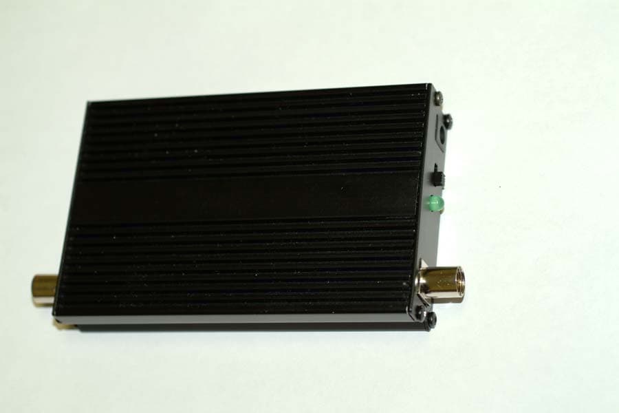
Rhein Tech Laboratories Mobile Communication Technologies, Inc. 360 Herndon Parkway 3W Mobile Amplifier Suite 1400 FCC: Part 22 & Industry Canada RSS-119 Herndon, VA 20170 FCC ID: OW5BST800 http://www.rheintech.com RTL WO: 2002166 Page 108 of 120 APPENDIX J: EXTERNAL PHOTOGRAPHS PHOTOGRAPH 4: EUT TOP VIEW Rhein Tech Laboratories Mobile Communication Technologies, Inc. 360 Herndon Parkway 3W Mobile Amplifier Suite 1400 FCC: Part 22 & Industry Canada RSS-119 Herndon, VA 20170 FCC ID: OW5BST800 http://www.rheintech.com RTL WO: 2002166 Page 109 of 120 PHOTOGRAPH 5: EUT BOTTOM VIEW Rhein Tech Laboratories Mobile Communication Technologies, Inc. 360 Herndon Parkway 3W Mobile Amplifier Suite 1400 FCC: Part 22 & Industry Canada RSS-119 Herndon, VA 20170 FCC ID: OW5BST800 http://www.rheintech.com RTL WO: 2002166 Page 110 of 120 PHOTOGRAPH 6: EUT OUTPUT SIDE Rhein Tech Laboratories Mobile Communication Technologies, Inc. 360 Herndon Parkway 3W Mobile Amplifier Suite 1400 FCC: Part 22 & Industry Canada RSS-119 Herndon, VA 20170 FCC ID: OW5BST800 http://www.rheintech.com RTL WO: 2002166 Page 111 of 120 PHOTOGRAPH 7: EUT SIDE VIEW Rhein Tech Laboratories Mobile Communication Technologies, Inc. 360 Herndon Parkway 3W Mobile Amplifier Suite 1400 FCC: Part 22 & Industry Canada RSS-119 Herndon, VA 20170 FCC ID: OW5BST800 http://www.rheintech.com RTL WO: 2002166 Page 112 of 120 PHOTOGRAPH 8: EUT SIDE VIEW Rhein Tech Laboratories Mobile Communication Technologies, Inc. 360 Herndon Parkway 3W Mobile Amplifier Suite 1400 FCC: Part 22 & Industry Canada RSS-119 Herndon, VA 20170 FCC ID: OW5BST800 http://www.rheintech.com RTL WO: 2002166 Page 113 of 120 PHOTOGRAPH 9: EUT END VIEW Rhein Tech Laboratories Mobile Communication Technologies, Inc. 360 Herndon Parkway 3W Mobile Amplifier Suite 1400 FCC: Part 22 & Industry Canada RSS-119 Herndon, VA 20170 FCC ID: OW5BST800 http://www.rheintech.com RTL WO: 2002166 Page 114 of 120 PHOTOGRAPH 10: MAGNETIC MOUNT ANTENNA WITH CONNECTOR Rhein Tech Laboratories Mobile Communication Technologies, Inc. 360 Herndon Parkway 3W Mobile Amplifier Suite 1400 FCC: Part 22 & Industry Canada RSS-119 Herndon, VA 20170 FCC ID: OW5BST800 http://www.rheintech.com RTL WO: 2002166 Page 115 of 120 PHOTOGRAPH 11: 0DB GLASS MOUNT ANTENNA WITH CABLES AND CONNECTORS
ID Label/Location Info
Rhein Tech Laboratories Mobile Communication Technologies, Inc. 360 Herndon Parkway 3W Mobile Amplifier Suite 1400 FCC: Part 22 & Industry Canada RSS-119 Herndon, VA 20170 FCC ID: OW5BST800 http://www.rheintech.com RTL WO: 2002166 Page 99 of 120 APPENDIX C: LABEL AND LOCATION INFORMATION PHOTOGRAPH 1: LABEL LOCATION ON EUT BOTTOM Please refer to the following page for a sample label. FCC ID LABEL HERE Maximum power Contact us at: www.smoothtalker.com Model BST800 Frequency:TX 824-849MHz Output Power:Max 3 watt Structure: Full Duplex Full Duplex Gain: TX Max 13dB RX Max13dB RX 869-894MHz Variable Gain R.F. Booster S/N#XXX123 FCC ID: OW5BST800 Smoothtalker Canada: XXXXXXXXXX TM BandPCS Antenna Gain Only
Internal Photos
Rhein Tech Laboratories Mobile Communication Technologies, Inc. 360 Herndon Parkway 3W Mobile Amplifier Suite 1400 FCC: Part 22 & Industry Canada RSS-119 Herndon, VA 20170 FCC ID: OW5BST800 http://www.rheintech.com RTL WO: 2002166 Page 116 of 120 APPENDIX K: INTERNAL PHOTOGRAPHS PHOTOGRAPH 12: TOP OF INTERNAL PCB MOUNTED TO HEAT SINK Rhein Tech Laboratories Mobile Communication Technologies, Inc. 360 Herndon Parkway 3W Mobile Amplifier Suite 1400 FCC: Part 22 & Industry Canada RSS-119 Herndon, VA 20170 FCC ID: OW5BST800 http://www.rheintech.com RTL WO: 2002166 Page 117 of 120 PHOTOGRAPH 13: PCB FRONT VIEW Rhein Tech Laboratories Mobile Communication Technologies, Inc. 360 Herndon Parkway 3W Mobile Amplifier Suite 1400 FCC: Part 22 & Industry Canada RSS-119 Herndon, VA 20170 FCC ID: OW5BST800 http://www.rheintech.com RTL WO: 2002166 Page 118 of 120 PHOTOGRAPH 14: PCB REAR VIEW
RF Exposure Info
Rhein Tech Laboratories Mobile Communication Technologies, Inc. 360 Herndon Parkway 3W Mobile Amplifier Suite 1400 FCC: Part 22 & Industry Canada RSS-118 Herndon, VA 20170 FCC ID: OW5BST800 http://www.rheintech.com RTL WO: 2002166 Page 102 of 120 APPENDIX F: MAXIMUM PERMISSIBLE EXPOSURE FCC RULES AND REGULATIONS PART 1.1307, 1.1310, 2.1091, 2.1093: RF EXPOSURE COMPLIANCE 1. GENERAL INFORMATION: • FCCID: OW5BST800 • Environment: General Population/Uncontrolled Exposure • Device category: Mobile per Part 2.1093 2. OPERATING CONFIGURATIONS AND TEST CONDITIONS: 2.1 ANTENNA TYPE(S): Antenna Type Gain (dBi) M OBILE C OMMUNICATIONS T ECHNOLOGIES , I NC . F LEXIBLE D UAL C OIL WIRE 2.6 M OBILE C OMMUNICATIONS T ECHNOLOGIES , I NC M AGNETIC M OUNT 1/8 WAVE WIRE 1.0 M OBILE C OMMUNICATIONS T ECHNOLOGIES , I NC G LASS M OUNT 1/8 WAVE WIRE 0.2 3. OPERATING CONDITIONS: The BST800 Amplifier is a automobile cellular band amplifier for uplink frequencies 824-849 MHz; the peak conducted and peak radiated (ERP) output power does not exceed 3 W. 4. TEST SIGNAL, TIME-AVERAGING, MAX. MEASURED OUTPUT POWER: Modulation Type/Modes: CDMA1, CDMA2000, WCDMA, and GSM with Edge and GPRS Frequency Range Frequency Tolerance (ppm) Emission Designator 824-849 MHz N/A AMP Output Power (Watt/dBm) High (Watt) High (dBm) Time averaging (__% Duty Cycle) Conducted 3.0 34.8 N/A Rhein Tech Laboratories Mobile Communication Technologies, Inc. 360 Herndon Parkway 3W Mobile Amplifier Suite 1400 FCC: Part 22 & Industry Canada RSS-118 Herndon, VA 20170 FCC ID: OW5BST800 http://www.rheintech.com RTL WO: 2002166 Page 103 of 120 From FCC 1.1310 Table 1A, the maximum permissible RF exposure for an uncontrolled environment is f/1500 mW/cm 2 = 0.55 –0.57 mW/cm 2 . The Electric field generated for a 0.57mW/cm 2 exposure (S) is calculated as follows: S = E 2 /Z where : S = Power density E = Electric field Z = Impedance. ZSE⋅= 0.57 mW/cm 2 = 5.7 W/m 2 The impedance of free space is 377 ohms, where E and H fields are perpendicular. Thus: 3777.5⋅=E = 46.4 V/m which is equivalent to 0.57mW/cm 2 Using the relationship between Electric field E, Power in watts P, and distance in meters d, the corresponding Antenna numeric gain G and the transmitter output power: d GP mVE ×× = 30 )/( Power density: 9.2148 )/( 2 2 E cmmWP d = MPE Calculation: The maximum distance from the antenna at which MPE is met or exceeded is calculated from the equation relating field strength E in V/m, transmit power P in Watts, transmit antenna numeric gain G, and separation distance in meters above, and solving for d below: E GP d ×× = 30 4.46 8.1288.130 18.0 ×× =m The limit for general population/uncontrolled exposure environment from 300 to 1500MHz is f/1500 2 /cmmW . SEPARATION DISTANCE: Highest Antenna Gain = 1.8 Power B (Watt) = 1.288 Separation Distance (in) (m) 7.1 0.18 Notes: B = Measured ERP
Test Report
Engineering and Testing for EMC and Safety Compliance 360 Herndon Parkway, Suite 1400 Herndon, VA 20170 Phone: 703-689-0368; Fax: 703-689-2056; Metro: 703-471-6441 CERTIFICATION APPLICATION REPORT FCC PART 22 CERTIFICATION & INDUSTRY CANADA RSS-118 CERTIFICATION Test Lab: Rhein Tech Laboratories, Inc. Phone: 703-689-0368 360 Herndon Parkway Fax: 703-689-2056 Suite 1400 Web Site: www.rheintech.com Herndon, VA 20170 E-Mail: [email protected] Applicant Information: Mobile Communications Technologies Inc. (MCT, Inc.) Contact: John Vagas Phone: 905-726-3444 ext. 202 360 Industrial Pkwy South Fax: 905-726-4233 Unit 1 Aurora, Ontario L4G 3V7 Canada E-Mail: [email protected] FCC ID: OW5BST800 GRANTEE FRN NUMBER: 0007702509 PLAT FORM: N/A RTL WORK ORDER NUMBER: 2002166 MODEL(S): BST800 RTL QUOTE NUMBER: QRTL02-555 DATE OF TEST REPORT: November 13, 2002 American National Standard Institute: ANSI C63.4: Methods of Measurement of Radio-Noise Emissions from Low-Voltage Electrical and Electronic Equipment in the Range of 9 kHz to 40 GHz ANSI/TIA/EIA603- 1992 Land Mobile FM or PM Communications Equipment Measurement and Performance Standards ANSI/TIA/EIA 603-1-1998 Addendum to ANSI/TIA/EIA 603-1992 TIA/EIA /IS-98-A Recommended Minimum Performance standards for Dual-Mode Wideband Spectrum Cellular Mobile Stations FCC Classification: AMP - Amplifier FCC Rule Part(s): Part 22: Public Mobile Services Industry Canada Standard: RSS-118: Land and Subscriber Stations: Voice, Data and Tone Modulated, Angle Modulation Radiotelephone Transmitters and Receivers Operating in the Cellular Mobile Bands 824-489 MHz and 869-894 MHz Digital Interface Information Digital Interface was found to be compliant Receiver Information Receiver was found to be compliant Frequency Range (MHz) Output Power (W) Frequency Tolerance Emission Designator 824-849 3 N/A AMP We, the undersigned, hereby declare that the equipment tested and referenced in this report conforms to the identified standard(s) as described in this test report. No modifications were made to the equipment during testing in order to achieve compliance with these standards. Furthermore, there was no deviation from, additions to, or exclusions from the FCC Part 2, FCC Part 22, Industry Canada RSS-118, and ANSI C63.4. Signature: Date: November 13, 2002 Typed/Printed Name: Desmond A. Fraser Position: President No part of this report may be reproduced without the full written approval of Rhein Tech Laboratories, Inc. Rhein Tech Laboratories Mobile Communication Technologies, Inc. 360 Herndon Parkway 3W Mobile Amplifier Suite 1400 FCC: Part 22 & Industry Canada RSS-118 Herndon, VA 20170 FCC ID: OW5BST800 http://www.rheintech.com RTL WO: 2002166 Page 2 of 120 TABLE OF CONTENTS 1 GENERAL INFORMATION ............................................................................................................................... 7 1.1 TEST FACILITY .............................................................................................................................................. 7 1.2 RELATED SUBMITTAL(S)/GRANT(S) ........................................................................................................ 7 2 TESTED SYSTEM DETAILS.............................................................................................................................. 8 2.1 JUSTIFICATION.............................................................................................................................................. 8 2.2 COMPONENTS................................................................................................................................................ 8 2.3 CONFIGURATION OF TESTED SYSTEM.................................................................................................... 8 3 FCC PART 2.1033(C)(8); DC VOLTAGES AND CURRENTS ....................................................................... 9 4 FCC RULES AND REGULATIONS PART 2.1046 (A): RF POWER OUTPUT: CONDUCTED.............. 10 4.1 TEST PROCEDURE....................................................................................................................................... 10 4.2 TEST DATA ................................................................................................................................................... 10 4.3 TEST EQUIPMENT ....................................................................................................................................... 25 5 FCC RULES AND REGULATIONS PART 2.1046 (A); RF POWER OUTPUT: RADIATED ERP PER PART 22.913 ................................................................................................................................................................ 26 5.1 TEST PROCEDURE....................................................................................................................................... 26 5.2 TEST DATA ................................................................................................................................................... 26 5.3 TEST EQUIPMENT ....................................................................................................................................... 27 6 FCC RULES AND REGULATIONS PART 2.1049 (C) (1): OCCUPIED BANDWIDTH ........................... 28 6.1 TEST PROCEDURE....................................................................................................................................... 28 6.2 TEST DATA ................................................................................................................................................... 28 6.3 TEST EQUIPMENT ....................................................................................................................................... 35 7 FCC RULES AND REGULATIONS PART 2.1051: SPURIOUS EMISSIONS AT ANTENNA TERMINALS .............................................................................................…
Text truncated - open the document above for the full version.
Test Setup Photos
Rhein Tech Laboratories Mobile Communication Technologies, Inc. 360 Herndon Parkway 3W Mobile Amplifier Suite 1400 FCC: Part 22 & Industry Canada RSS-119 Herndon, VA 20170 FCC ID: OW5BST800 http://www.rheintech.com RTL WO: 2002166 Page 106 of 120 APPENDIX I: TEST CONFIGURATION PHOTOGRAPHS PHOTOGRAPH 2: RADIATED EMISSIONS FRONT VIEW Rhein Tech Laboratories Mobile Communication Technologies, Inc. 360 Herndon Parkway 3W Mobile Amplifier Suite 1400 FCC: Part 22 & Industry Canada RSS-119 Herndon, VA 20170 FCC ID: OW5BST800 http://www.rheintech.com RTL WO: 2002166 Page 107 of 120 PHOTOGRAPH 3: RADIATED EMISSIONS REAR VIEW
Contact Information
Applicant
Tom Vagenas(Director Of Operations)
Technical Contact
Rhein Tech LaboratoriesDesmond Fraser
703 689 0368
360 Herndon Parkway · Herndon, Virginia · United States
Test Firm
Rhein Tech Laboratories, Inc.Rick McMurray
Technical Specifications
| # | Rule Parts | Frequency Range | Power Output | Emission |
|---|---|---|---|---|
| 1 | 22.901(d) | 824 MHz - 849 MHz | 3 W | AMP |
Other Applications from Mobile Communications Technologies Inc.
OW5BST1901
May 09, 2004external radio frequency power amplifier (erfpa)
Equipment Class
AMP - Amplifier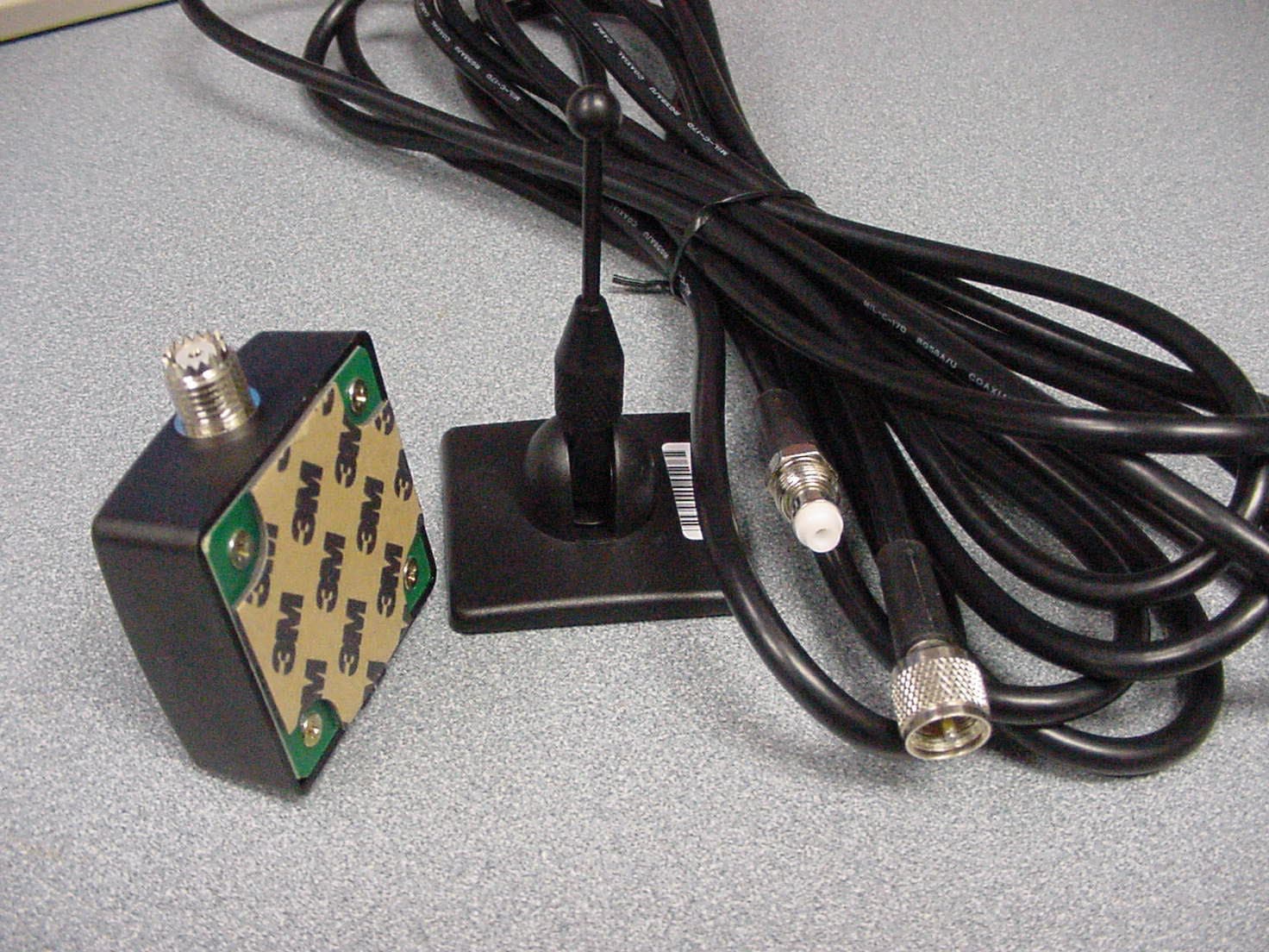
OW5BST850
Sep 21, 2003GSM/GPRS/TDMA/EDGE Cellular Band Amplifier
Equipment Class
AMP - Amplifier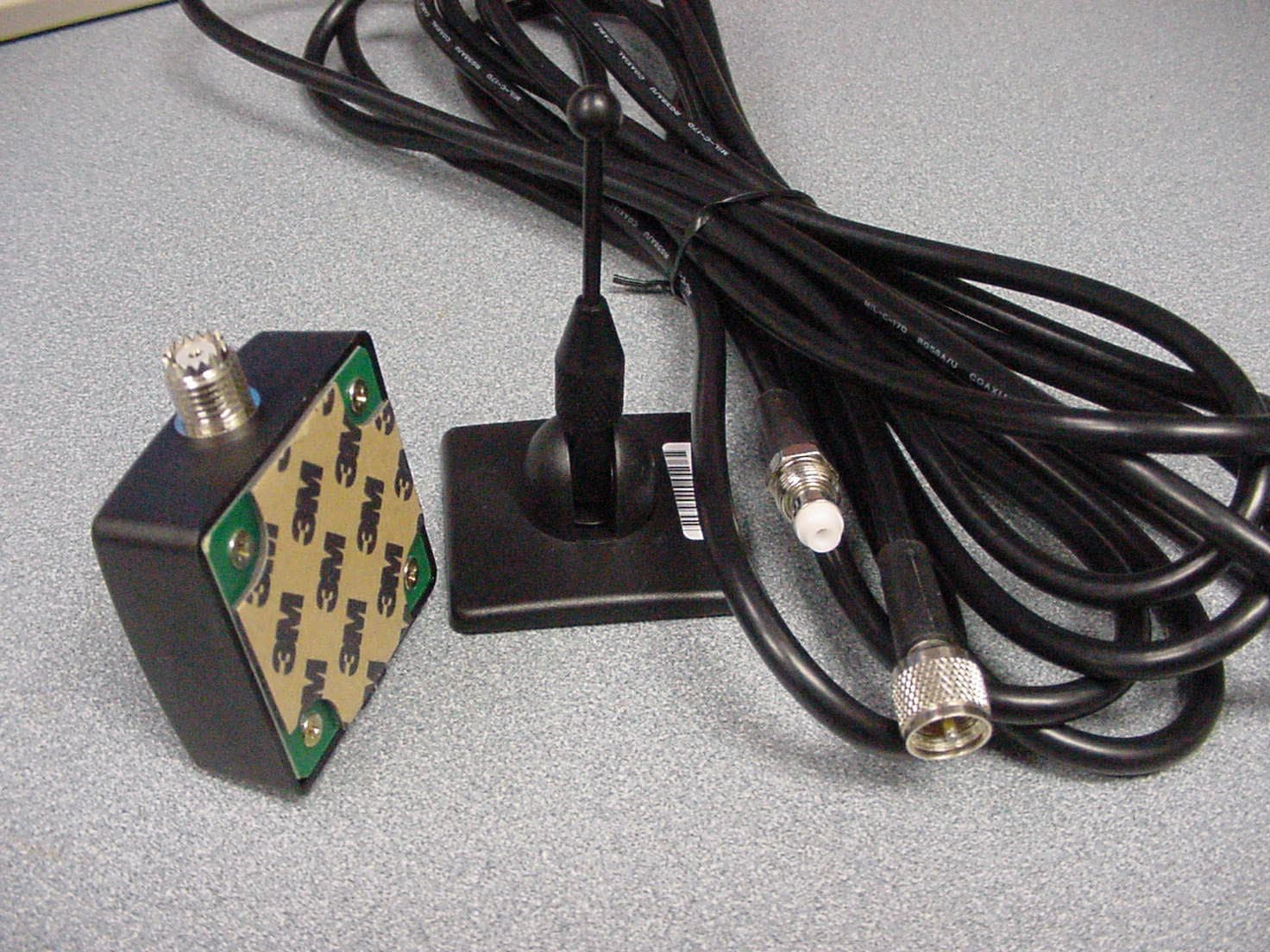
OW5BST1900
Jul 23, 2003GSM/GPRS PCS Band Amplifier
Equipment Class
AMP - Amplifier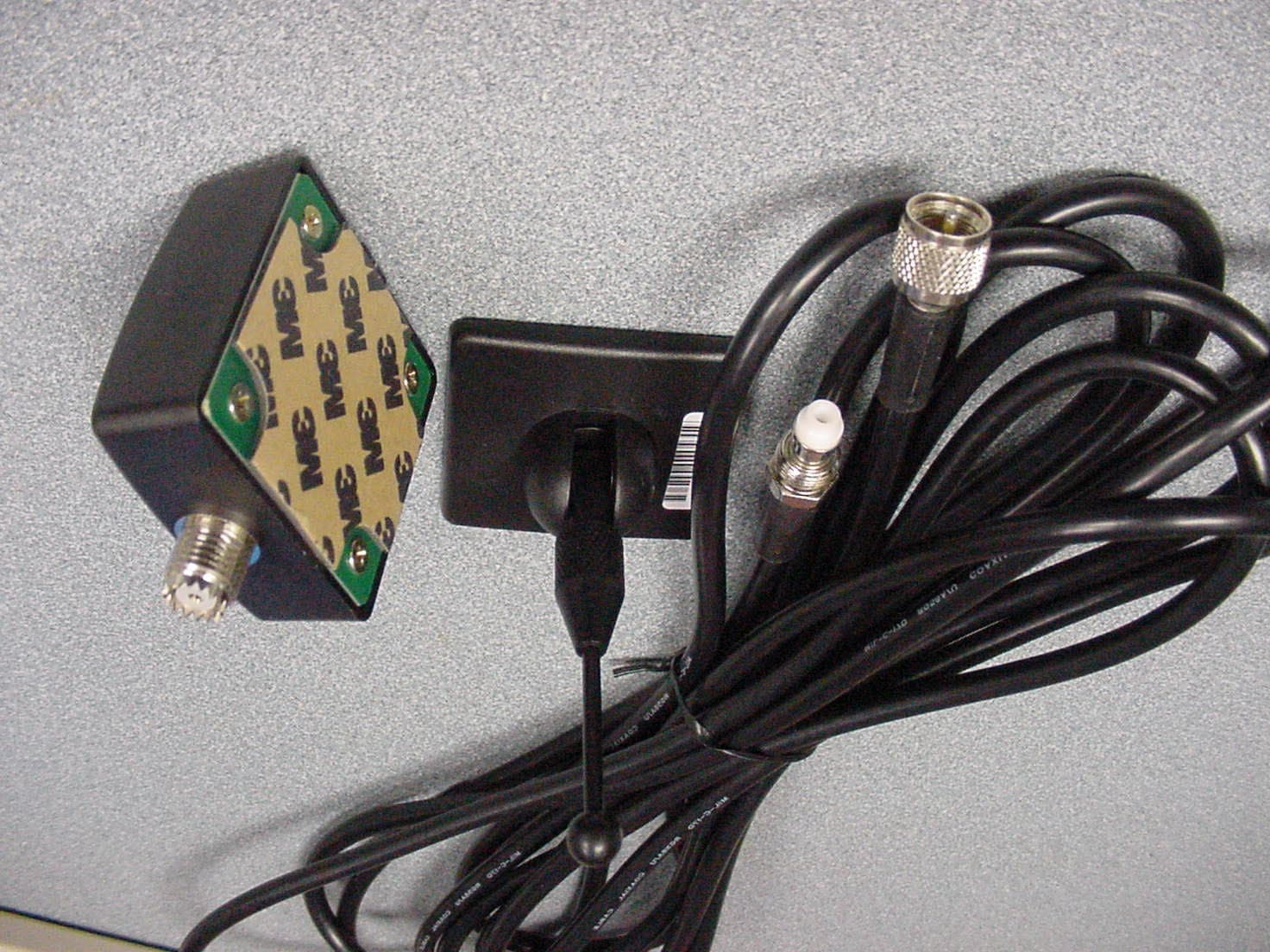
OW5BST801
Nov 20, 2002IDEN Booster/Amplifier (
Equipment Class
AMP - Amplifier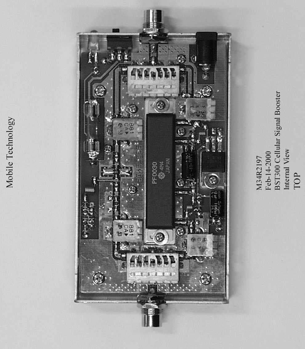
OW5BST300
Jun 27, 2001Mobile T.D.M.A Cellular Booster
Equipment Class
AMP - Amplifier