OWR40089MIFARE Contactless Card Reader
NXP Austria GmbH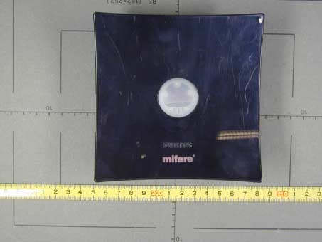
Click to zoom
Application Details
- Equipment Class
- DXX - Part 15 Low Power Communication Device Transmitter
- Date of Grant
- Mar 21, 2002
- Application Purpose
- Original Equipment
- Date of Application
- Mar 21, 2002
- Equipment Note
- MIFARE Contactless Card Reader
- Frequency Range
- 13.56000000 - 13.56000000
- Company
- NXP Austria GmbH
- Country
- Austria
Documents & Files
Document Text
Text extracted from the exhibit documents filed with the FCC. Open a document above to read the original.
Users Manual
Declaration Of Conformity Date:March 18, 2002 Test Report Number:031802A1-10592-3mod Type of Equipment:Reader Model Number:MF RD 700 U(USB) Rules and Regulations: United States Code of Federal Regulations 47 Part 15 – Electromagnetic Emissions, Class C Devices Standards: ANSI C63.4-1992, Methods of Measurement of Radio-Noise Emissions from Low-Voltage Electrical Equipment in the Range of 9kHz to 40 GHz. Section 11.0 Measurement of Information Technology Equipment (ITE) Verified By Signature:Date:March 18, 2002 Thomas P. Sims Diversified T.E.S.T. Technologies, Inc. P.O. Box 8, 556 Route 222 Groton, NY 13073 Phone: (607) 898-4218FAX: (607) 898-4830 Responsible Party: Philips Semiconductors Gratkorn GmbH declares that the equipment specified above conforms to the referenced Rules, Regulations and Standards. Signature:Date: Name: Company: Address: Phone: FAX: DIVERSIFIED T.E.S.T. TECHNOLOGIES, INC. FCC Part 15 Class C VERIFICATION REPORT for Philips Semiconductors Gratkorn GmbH Mikron-Weg 1 8101 Gratkorn Austria Product: Reader Model Number: MF RD 700 U(USB) Report Number: 031802A1-10592-3mod Test Start Date: March 18, 2002 REVIEWED BY: Thomas P. Sims PREPARED BY: Gary Tucker FCC PART 15 CLASS B TECHNICAL REPORT FOR THE Equipment Type: Reader Model Number: MF RD 700 U(USB) Report Number: 031802A1-10592-3mod Date: March 18, 2002 Original Release:XChange to Product: Equipment Type:Reader Model Number:MF RD 700 U(USB) Tested for Compliance with: 47CFR15/ANSI C63.4-1992 Radiated Emissions CLASS C PASS PREPARED FOR:Philips Semiconductors Gratkorn GmbH Mikron-Weg 1 8101 Gratkorn Austria PREPARED BY:Diversified T.E.S.T. Technologies, Inc. P.O. Box 8, 556 Route 222 Groton, NY 13118 General Overview Equipment Under Test:Reader Model Number:MF RD 700 U(USB) Purpose of Test The purpose of this test is to verify that the latest changes to the EUT complies with or exceeds the performance levels listed in the applicable Standards referenced in table 1. Table 1: Directive or StandardDescription CFR 47 Part 15 Subpart CRadio Frequency Devices, Subpart C- Intentional Radiators ANSI C63.4-1992Methods of Measurement of Radio-Noise Emissions from Low-Voltage Electrical and Electronic Equipment in the Range of 9 kHz to 40 GHz TEST CONFIGURATION DIAGRAMS AND SYSTEM DETAILS See Addendum A, EMC Test Report No. 55435-10592-3mod, for additional details TEST DATA This report contains data that was produced by, Senton GmbH EMI/EMC Test Center, a recognized, subcontracted laboratory NOT ACCREDITED by NVLAP for the test methods performed. This test report includes the following documents published by the Senton GmbH EMI/EMC Test Center, Aeussere Fruehlingstrasse 45, D-94315 Straubing, Germany. - Addendum A: EMC Test Report No. 55435-10592-3mod SUMMARY (a) Radiated Emissions – Passed The EUT was tested by Senton GmbH, for Class C Information Technology Equipment Radiated Emission testing was conducted on a 10 m OATS at 5 VDC to assure the EUT met all requirements as noted above.
Users Manual
READER COMPONENTS MF RD700 PEGODA Contactless Smart Card Reade r November 2001 Preliminary Product Specification Revision 1.0 PUBLIC Philips Semiconductors Philips Semiconductors Preliminary Specification Rev. 1.0 November 2001 MIFARE Pegoda Contactless Card Reader MF RD700 2 CONTENTS 1 GENERAL INFORMATION ........................................................................................................................ 3 1.1 S COPE.................................................................................................................................................. 3 1.2 G ENERAL DESCRIPTION......................................................................................................................... 3 1.3 F EATURES............................................................................................................................................. 4 1.4 O RDERING INFORMATION....................................................................................................................... 4 2 FUNCTIONAL UNITS................................................................................................................................. 5 2.1 MF RD700 P EGODA BLOCK DIAGRAM................................................................................................... 5 2.2 USB T YPE B PLUG................................................................................................................................7 2.3 P OWER SUPPLY..................................................................................................................................... 8 3 ELECTRICAL CHARACTERISTICS ......................................................................................................... 9 3.1 O PERATING CONDITION RANGE.............................................................................................................. 9 3.2 C URRENT CONSUMPTION....................................................................................................................... 9 3.3 O PERATING DISTANCE............................................................................................................................ 9 3.4 I NTERFACE CHARACTERISTICS................................................................................................................ 9 3.4.1 USB-Charcteristics ....................................................................................................................... 9 4 ELECTROMAGNETIC COMPATIBILITY ................................................................................................10 4.1 FCC C LASS A DECLARATION OF CONFORMITY..................................................................................... 10 4.2 FCC D ECLARATION OF CONFORMITY OF A CLASS A DIGITAL DEVICE...............FEHLER! TEXTMARKE NICHT DEFINIERT . 4.3 CE D ECLARATION OF CONFORMITY...................................................................................................... 12 4.4 M ECHANICAL SPECIFICATION................................................................................................................ 13 4.4.1 Side View ................................................................................................................................... 13 4.4.2 Bottom View ............................................................................................................................... 14 5 REVISION HISTORY................................................................................................................................ 15 Philips Semiconductors Preliminary Specification Rev. 1.0 November 2001 MIFARE Pegoda Contactless Card Reader MF RD700 3 1 GENERAL INFORMATION 1.1 Scope This document describes the basic functionality and the electrical specifications of the MF RD700 ëPegodaí reader. This contactless reader is designed for an easy reader adaptation to a PC to use this device for test and application purposes. Furthermore this reader can be taken as a reference design for new reader development based on the MF RC 500 reader IC. 1.2 General Description The MIFARE Æ Pegoda reader, the MF RD700, is a new contactless reader based on the MF RC500 reader IC. The MF RC500 is member of a new family for highly integrated reader ICs for contactless communication at 13.56 MHz. All layers of ISO14443A as well as the MIFARE Æ classic protocol are supported. The Pegoda reader is designed to fulfil several requirements. It covers all functionality of the MF RC500 to be able to use this reader as a reference design for a new hardware design based on the MF RC500 reader IC and is designed for easy PC adaptation and application development as well. The Pegoda is the basic component for 2 evaluation kits: • MF EV700 evaluation kit. This kit is ready to use the Pegoda reader to develop a PC based application. This package includes the Pegoda reader, a complete documentation including software libraries and description as well as the demonstration program MIFAREWnd covering all MIFARE and ISO 14443A commands. • MF EV800 full evaluation kit The MF EV800 gives the user the possibility to design his own reader either based on the Pegoda or taking the Pegoda as a reference design for an own development. The MFEV800 package includes the MF EV700 package and additionally 5 MF RC500 samples and a reader PCB having the possibility to connect the reader using an RS 232 interface. . Philips Semiconductors Preliminary Specification Rev. 1.0 November 2001 MIFARE Pegoda Contactless Card Reader MF RD700 4 1.3 Features • contactless smart card reader • based on the MF RM 700 reader module containing the MF RC 500 reader IC • contactless operating frequency 13.56 MHz • Supports MIFARE Æ Dual Interface Card ICs and ISO 14443A part 1- 4 • Supports MIFARE Æ Classic protocol • typical operating distance: 75mm • CE and FCC compliant • USB host interface • USB bus powered 5 VDC power suppl…
Text truncated - open the document above for the full version.
Cover Letter(s)
Philips Semiconductors Gratkorn GmbH Mikron-Weg 1 8101 Gratkorn AUSTRIA Request for Confidentiality March 28, 2002 American Telecommunications Certification Body, Inc. 6731 Whittier Avenue Suite C110 McLean, VA 22101 RE: MF RD 700 U (USB) Certification Application FCC ID: OWR40089 Please be advised that the following information is to be held confidential and behalf of Philips Semiconductors Gratkorn GmbH • Block diagrams • Schematics The application contains technical information which deems to be trade secrets and proprietary. If made public, the information might be used to the disadvantage of the applicant in the market place. Thank you for your attention to this matter. Johann Roidt
External Photos
FCC ID: External Photographs Page 1 of 2 FCC ID OWR40089 Philips Semiconductors Gratkorn GmbH External Photographs FCC ID: External Photographs Page 2 of 2
ID Label/Location Info
FCC ID: External Photographs Page 1 of 1 FCC ID OWR40089 Philips Semiconductors Gratkorn GmbH Label Information
Internal Photos
FCC ID:Internal Photographs Page 1 of 5 FCC ID OWR40089 Philips Semiconductors Gratkorn GmbH Internal Photographs FCC ID:Internal Photographs Page 2 of 5 FCC ID:Internal Photographs Page 3 of 5 FCC ID:Internal Photographs Page 4 of 5 FCC ID:Internal Photographs Page 5 of 5
Operational Description
Philips SemiconductorsObjective Specification Rev. 1.0 August 2001 MIFARE Contactless Card ReaderMF RD700 3 1 GENERAL INFORMATION 1.1 Scope This document describes the functionality of the MF RD700 ‘Pegoda’ reader. It includes the functional and electrical specifications and gives details, how to use or design-in this device from a system and hardware viewpoint. This reader is designed for an easy adaptation of a contactless reader to a PC and ready to design a new application. 1.2 General Description The MIFARE ® Pegoda reader, the MF RD700, is a new contactless reader based on the MF RC500 reader IC. The MF RC500 is member of a new family for highly integrated reader ICs for contactless communication at 13.56 MHz. The MF RD700 supports all layers of ISO14443A in combination with MIFARE Dual Interface cards as well the MIFARE Classic protocol. The Pegoda reader is designed to fulfil several requirements. It covers all functionality of the MF RC500 to be able to use this reader as a reference design for a new MF RC500 based reader and is designed for easy PC adaptation and application development. The Pegoda is the basic component for 2 evaluation kits: • MF EV700 evaluation kit. This kit is ready to use the Pegoda reader to develop an application based on that reader. This package includes the Pegoda reader, a complete documentation including software libraries and description as well as the demonstration program MIFAREWnd covering all MIFARE and ISO 14443A commands • MF EV800 full evaluation kit The MF EV800 gives the user the possibility to design his own reader either based on the Pegoda or taking the Pegoda as a reference design for an own development. The MFEV800 package includes the MF EV700 package and additionally some MF RC500 samples and a reader print having the possibility to connect the reader using an RS 232 interface. . Philips SemiconductorsObjective Specification Rev. 1.0 August 2001 MIFARE Contactless Card ReaderMF RD700 4 1.3 Features • contactless smart card reader • based on the MF RC500 • contactless operating frequency 13.56 MHz • Supports MIFARE ® Dual Interface Card ICs and ISO 14443A part 1- 4 • Supports MIFARE ® Classic protocol • typical operating distance: 75mm • CE and FCC compliant • USB host interface • USB bus powered 5 VDC power supply • Accessible via various serial protocols up to 115200 baud • Unique serial number of each reader device 1.4 Ordering Information The MF RD 700 ‘Pegoda’ is available in 2 evaluation kits. Type12NCDescription MF EV7009352 699 27122 evaluation kit containing: MF RD700 Pegoda reader, documentation software CD MF EV8009352 699 28122 full evaluation kit containing: MF RD700 Pegoda reader documentation and software CD MF RM700 reader module PCB with RS232 connector 5 MF RC 500 samples Small directly matched antenna 50 Ohm matching circuit Table 1-1: MF RD700 Ordering Information
Test Report
EMV-Pr ̧fzentrum EMI/EMC-Testcenter Page 1 of 46 Pages Straubing, November 22, 2001 T E S T - R E P O R T No. 55435-10592-3mod for MF RD 700 U (USB) Applicant:Philips Semiconductors Gratkorn GmbH Purpose of testing:To show compliance with FCC Code of Federal Regulations, CFR 47, Part 15, Subpart C, Section 15.225 Note: The test data of this report relate only to the individual item which has been tested. This report shall not be reproduced except in full extent without the written approval of the testing laboratory. FCC-ID: OWR40089Test Report No. 55435-10592-3mod Page 2 of 46 Pages Table of Contents 1. Administrative Data ..............................................................................................3 2. Identification of Test Laboratory ...........................................................................4 3. Summary of Test Results.....................................................................................5 4. Operation Mode of EUT .......................................................................................6 5. Configuration of EUT and Peripheral Devices ......................................................7 6. Measuring Methods..............................................................................................8 6.1. Field strength of in-band emissions (ß15.225 (a)) and unwanted emissions < 30 MHz (ß15.225 (b)) ................................................8 6.2. Frequency tolerance (ß15.225 (c)) ................................................................9 6.3. Unwanted Emission 30 MHz - 1 GHz (ß15.225 (b)) .....................................11 7. Photographs of Test Setups...............................................................................13 7.1. Radiated Emissions 30 ñ 1000 MHz ...............................................................14 7.2. Radiated Emissions 30 ñ 1000 MHz (continued) ............................................15 8. Equipment List ...................................................................................................16 9. Referenced Regulations.....................................................................................18 10. List of Measurements.........................................................................................19 11. Test Results .......................................................................................................20 12. Charts taken during testing ................................................................................26 FCC-ID: OWR40089Test Report No. 55435-10592-3mod Page 3 of 46 Pages 1.Administrative Data Equipment Under Test (EUT):MF RD 700 U (USB) Serial number(s):--- Type of equipment:Reader Type of emission:10K0A1D Parts/accessories:--- FCC-ID:OWR40089 Applicant:Philips Semiconductors Gratkorn GmbH (full address)Mikron-Weg 1 8101 Gratkorn AUSTRIA Contract identification:--- Contact person:Mr. Bergler Manufacturer:Philips Semiconductors Gratkorn GmbH Receipt of EUT:September 6, 2001 Dates of test:September to October 2001 Note:--- Responsible for testing:Thomas Eberl Responsible for test report:Johann Roidt (cj) FCC-ID: OWR40089Test Report No. 55435-10592-3mod Page 4 of 46 Pages 2.Identification of Test Laboratory Test Laboratory:Senton GmbH EMI/EMC Test Center (full address):Aeussere Fruehlingstrasse 45 D-94315 Straubing Germany Contact person:Mr. Johann Roidt Communication:Telephone(+49) 0 94 21 / 55 22-0 Fax (+49) 0 94 21 / 55 22-99 eMail:[email protected] FCC registration number:90926 Industry Canada file number:IC 3050 FCC-ID: OWR40089Test Report No. 55435-10592-3mod Page 5 of 46 Pages 3.Summary of Test Results The tested sample complies with the requirements for set forth in the The Code of Federal Regulations 47, Part 15, Subpart C, Section 15.225 of the Federal Communication Commission (FCC). Johann RoidtThomas Eberl Technical ManagerTest Engineer FCC-ID: OWR40089Test Report No. 55435-10592-3mod Page 6 of 46 Pages 4.Operation Mode of EUT Continously reading a TAG FCC-ID: OWR40089Test Report No. 55435-10592-3mod Page 7 of 46 Pages 5.Configuration of EUT and Peripheral Devices Configuration of cables of EUT Not applicable Configuration of peripheral devices connected to EUT All tests were performed with the EUT connected to a personal computer via USB bus. EUT was powered from USB bus. FCC-ID: OWR40089Test Report No. 55435-10592-3mod Page 8 of 46 Pages 6.Measuring Methods 6.1. Field strength of in-band emissions (ß15.225 (a)) and unwanted emissions < 30 MHz (ß15.225 (b)) Radiated emissions in the frequency range 9 kHz ñ 30 MHz will be measured initially at a distance of 3 meters. A prescan at 3 meter distance will be performed in a shielded room with the detector of the spectrum analyzer or EMI Receiver set to peak. Final measurement is then performed at 30 meter distance. In case the regulation requires testing at other distances, the result will be extrapolated. The extrapolation factor will be determined by making a second measurement at 10 meter distance. The provisions of 15.31 (d) apply. According to section 15.209 (d) final measurementis performed with the detector set to Quasi Peak except for the frequency bands 9 ñ 90 kHz and 110 ñ 490 kHz where average detector is employed. FCC-ID: OWR40089Test Report No. 55435-10592-3mod Page 9 of 46 Pages 6.2. Frequency tolerance (ß15.225 (c)) 6.2.1.Frequency stability vs. temperature The frequency stability vs. temperature was measured with a spectrum analyzer connected to the output of the transmitter power amplifier (conducted measurement) via dummy load while EUT was operating in transmit mode using the assigned frequency. The trace mode of the spectrum analyzer was set to write with frequency count mode activated: RBW = 100 Hz, VBW = 100 Hz, span = 20 kHz, sweep = 1.5 s (auto mode) See figure 1 for the measurement setup. Test equipment used (see equipment list for details): 02, 18, 51, 54, 69, 70, 71 6 7 4 5 1 2 3 Figure 1: Measurement setup for testing with…
Text truncated - open the document above for the full version.
Test Setup Photos
FCC-ID: OWR40089Test Report No. 55435-10592-3 Page 14 of 46 Pages 7.1. Radiated Emissions 30 ñ 1000 MHz FCC-ID: OWR40089Test Report No. 55435-10592-3 Page 15 of 46 Pages 7.2. Radiated Emissions 30 ñ 1000 MHz (continued)
Contact Information
Applicant
Juergen Schroeder(Senior Product Manager)
Technical Contact
Senton GmbHJohann Roidt
[email protected]+49 9421 55 22 12
Aeussere Fruehlingstrasse 45 · Straubing · Germany
Non-Technical Contact
Senton GmbHJohann Roidt
[email protected]+49 9421 55 22 13
Test Firm
TUV SUD Product Service GmbH PS-EMC-STRRainer Heller
Technical Specifications
| # | Rule Parts | Frequency Range | Power Output |
|---|---|---|---|
| 1 | 15C | 13.56 MHz - 13.56 MHz | - |
Other Applications from NXP Austria GmbH
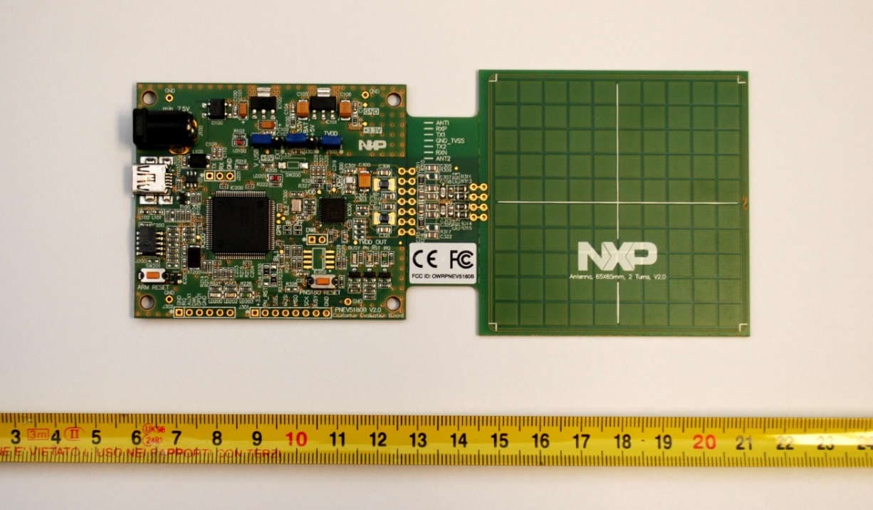
OWRPNEV5180B
Dec 23, 2015PN8180 Customer Evaluation Board
Equipment Class
DXX - Part 15 Low Power Communication Device Transmitter
OWROM5569-NT322E
Dec 16, 2015NTAG I2C plus Explorer Kit
Equipment Class
DXX - Part 15 Low Power Communication Device Transmitter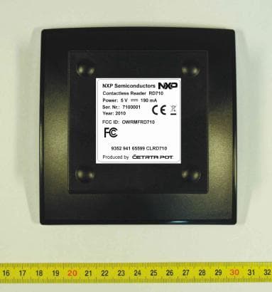
OWRMFRD710
May 09, 2011Contactless Reader
Equipment Class
DXX - Part 15 Low Power Communication Device Transmitter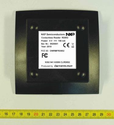
OWRMFRD852
May 09, 2011Contactless Reader
Equipment Class
DXX - Part 15 Low Power Communication Device Transmitter
OWRICODE-SLEV900
Jul 09, 2000RFID Tag
Equipment Class
DXX - Part 15 Low Power Communication Device Transmitter