OWRMFRD852Contactless Reader
NXP Austria GmbH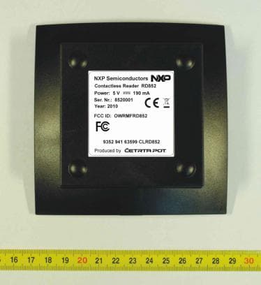
Click to zoom
Application Details
- Equipment Class
- DXX - Part 15 Low Power Communication Device Transmitter
- Date of Grant
- May 09, 2011
- Application Purpose
- Original Equipment
- Date of Application
- May 09, 2011
- Equipment Note
- Contactless Reader
- Frequency Range
- 13.56000000 - 13.56000000
- Company
- NXP Austria GmbH
- Country
- Austria
Documents & Files
Document Text
Text extracted from the exhibit documents filed with the FCC. Open a document above to read the original.
Users Manual
Document information Info Content Author Pavel Slamnik Author Role Design Engineer Keywords Contactless Reader RD710/RD852 Hardware User Manual RD710/RD852 Doc Rev 1.00 Approved — 18 Oct 2010 BL ID NXP Semiconductors BL ID Hardware User Manual Project Name: Hardware User Manual Project ID: 62743 SRS Template_vs 1.0 public © NXP B.V. 2010. All rights reserved Doc ID: DOC-XXXXXX Doc Rev 1.00 Approved — 18 Oct 2010 2 of 19 Copyright: @2009, NXP Semiconductors The information contained herein is the exclusive and confidential property of NXP Semiconductors and, except as otherwise indicated, shall not be disclosed or reproduced in whole or in part. Revision History Revision Date Description Author 0.90 2010.01.11 First Draft Version Pavel Slamnik 1.00 2010.10.18 Second Version Pavel Slamnik NXP Semiconductors BL ID Hardware User manual Project Name: Hardware User Manual Project ID: 62743 SRSt Template 1.0 public © NXP B.V. 2010. All rights reserved Doc ID: DOC-XXXXXX Doc Rev 1.00 Approved — 18 Oct 2010 3 of 19 Contents 1. CONTACTLESS READER RD710 / RD852 - PHOTO...........................................................................................4 2. CONTACTLESS READERS: RD710 AND RD852................................................................................................5 2.1. Operational desription..............................................................................................................................................5 3. CONTACTLESS READER RD710 / RD852 - SPECIFICATIONS............................................................................8 4. INSTALLING MANUAL.......................................................................................................................................10 4.1. Desktop use..........................................................................................................................................................10 4.2. USB type A-B plug cable.......................................................................................................................................11 4.3. Power supply.........................................................................................................................................................12 4.4. Electrical characteristics........................................................................................................................................13 5. USER MANUAL..................................................................................................................................................14 5.1. User manual..........................................................................................................................................................14 5.2. INSTRUCTIONS FOR SAFE WORK, MAINTAINING AND CARE...........................................................................15 5.3. ELECTROMAGNETIC COMPATIBILITY................................................................................................................16 1. 16 5.3.1. FCC Compliance Statement...............................................................................................................................16 5.3.2. COMPLIANCE INFORMATION according to 47CFR 2.1077...............................................................................17 5.3.3. CE Declaration of Conformity.............................................................................................................................18 6. WARRANTY, LIMITATIONS OF LIABILITY.........................................................................................................19 NXP Semiconductors BL ID Hardware User manual Project Name: Hardware User Manual Project ID: 62743 STS Template 1.0 public © NXP B.V. 2010. All rights reserved Doc ID: DOC-XXXXXX Doc Rev 1.00 Approved — 18 Oct 2010 4 of 19 1. CONTACTLESS READER RD710 / RD852 - PHOTO Figure 1: Contactless reader RD710 / RD852 – outside view. NXP Semiconductors BL ID Hardware User manual Project Name: Hardware User Manual Project ID: 62743 STS Template 1.0 public © NXP B.V. 2010. All rights reserved Doc ID: DOC-XXXXXX Doc Rev 1.00 Approved — 18 Oct 2010 5 of 19 2. CONTACTLESS READERS: RD710 AND RD852 2.1. Operational desription Family of contactless readers are composed from two contactless readers: RD710 and RD852. Both readers are made on the same printed circuit board Peridot 1.3. The main part of both readers with main microcontroller and all periferial devices (communication interfaces, connectors, external antena) are the same. Different part is integrated circuit (reader IC) with cryptology and antenna driver. Both readers support Contactless Smart Card Interface ISO14443A and ISO14443B standards. Data transmition rate between reader and contactless card is 106kbit, 212kbit, 424kbit up to 848kbit. Both readers have the same communication interfaces: one USB serial port, one RS232 serial ports (and additional serial port via MEC6 connector), one RS485 (configurable as half or full duplex) serial port, one JTAG connector for JTAG interface and one MEC6 connector for external LPC_COM board (LPC_COM board has included ethernet adapter). Both contactless readers, RD710 and RD852, are desktop readers and intended for use in development environment for development purposes – as reference contactless readers for working with MIFARE contactless cards. The main purpose is to develop new software (or hardware) for contactless readers based on LPC 1768 microcontroller and MIFARE reader ICs RC523 and MFRX852. Contactless readers RD710 and RD852 are connected to personal computer as peripheral devices via USB serial port. Both devices (RD710 and RD852) are bus powered.The data transfer between reader and card is carried by 13.56 MHz RF-field. The communication between reader and smartcard is dependant on the type of smartcard. Both readers suported various transfer rates specified in ISO standards. To start work…
Text truncated - open the document above for the full version.
External Photos
NXP Semiconductors GmbH RD852 Appendix A EUT Photo Page 3 of 11 ČETRTA POT, d.o.o., KRANJ Planina 3 , SI-4000 Kranj Slovenija 2. Appendix B: Reader RD852 – Reader External Photos Picture 3: RD852 reader – side view NXP Semiconductors GmbH RD852 Appendix A EUT Photo Page 4 of 11 ČETRTA POT, d.o.o., KRANJ Planina 3 , SI-4000 Kranj Slovenija Picture 4: RD852 reader - top side Picture 5: RD852 reader - bottom side
ID Label/Location Info
NXP Semiconductors GmbH RD852 Appendix A EUT Photo Page 1 of 3 ČETRTA POT, d.o.o., KRANJ Planina 3 , SI-4000 Kranj Slovenija Appendix: Reader RD852 Appendix: Reader RD852.................................................................................................................1 1. Appendix C: Reader RD852 – Label..........................................................................................2 NXP Semiconductors GmbH RD852 Appendix A EUT Photo Page 2 of 3 ČETRTA POT, d.o.o., KRANJ Planina 3 , SI-4000 Kranj Slovenija 1. Appendix C: Reader RD852 – Label Picture 1: RD852 reader - Label description NXP Semiconductors GmbH RD852 Appendix A EUT Photo Page 3 of 3 ČETRTA POT, d.o.o., KRANJ Planina 3 , SI-4000 Kranj Slovenija ID Location Info Picture 2: RD852 reader bottom side - Label with FCC ID position
Internal Photos
NXP Semiconductors GmbH RD852 Appendix A EUT Photo Page 2 of 9 ČETRTA POT, d.o.o., KRANJ Planina 3 , SI-4000 Kranj Slovenija 1. Appendix A: Reader RD852 – Reader Internal Photos Picture 1: RD852 reader pcb - top side Picture 2: RD852 reader pcb - bottom side
Test Report
NXP Semiconductors GmbH RD852 Appendix A EUT Photo Page 8 of 9 ČETRTA POT, d.o.o., KRANJ Planina 3 , SI-4000 Kranj Slovenija 5. Appendix E: List of Used Cables - USB Cable (Picture 9) Picture 9: USB Cable.
Test Report
TN4004 Izdaja/Issue: 01_01_06_2009 T251-0965R3/10 2 (36) Št. / No. Stran / Page CONTENTS PAGE 1 GENERAL 3 1.1 E QUIPMENT UNDER TEST DESCRIPTION 3 1.2 L IST OF MEASUREMENTS PERFORMED 4 1.3 O CCUPIED BANDWIDTH MEASUREMENT 4 1.4 Q UASI-PEAK DETECTOR 4 1.5 P EAK, RMS, AND AVERAGE DETECTORS 4 2 LIMITS 5 2.1 S UBPART C: INTENTIONAL RADIATORS 5 2.1.1 C ONDUCTED EMISSION LIMITS: 5 2.1.2 R ADIATED EMISSION LIMITS: 5 3 ALL TEST EQUIPMENT AND THEIR DESCRIPTION 6 3.1 G ENERAL INFORMATION 6 3.2 O THER INSTRUMENT INFORMATION AND AUXILIARY EQUIPMENT 7 4 GENERAL AND SPECIAL CONDITIONS DESCRIPTION 8 4.1 G ENERAL CONDITION DESCRIPTION 8 4.1.1 T EST ARRANGEMENT FOR CONDUCTED EMISSIONS 8 4.1.2 T EST ARRANGEMENT FOR CONDUCTED EMISSIONS- FLOOR-STANDING EQUIPMENT 8 4.1.3 T EST ARRANGEMENT FOR RADIATED EMISSIONS TABLETOP EQUIPMENT 9 4.1.4 T EST ARRANGEMENT FOR RADIATED EMISSIONS FLOOR-STANDING EQUIPMENT 9 4.1.5 T EST ARRANGEMENT FOR FLOOR-STANDING EQUIPMENT 10 4.1.6 T EST ARRANGEMENT FOR FLOOR-STANDING EQUIPMENT 10 4.1.7 P LACEMENT AND MANIPULATION OF INTERCONNECT CABLING (OR WIRING) OF TABLETOP EQUIPMENT 10 4.1.8 T EST CONFIGURATION/ARRANGEMENT FOR COMBINATION FLOOR-STANDING AND TABLETOP EQUIPMENT 11 4.2 S PECIAL CONDITION DESCRIPTION 11 5 TEST SUMMARY 12 5.1 P URPOSE OF THE TEST 12 6 EMISSION TESTS 13 6.1 C ONDUCTED EMISSION MEASUREMENT (INTENTIONAL RADIATOR) 13 6.1.1 T EST INSTRUMENTS 13 6.1.2 T EST PROCEDURE 13 6.1.3 T EST SETUP 14 6.1.4 T EST RESULTS 14 6.2 B ANDWIDTH OF THE EMISSION (INTENTIONAL RADIATOR) 19 6.2.1 T EST INSTRUMENTS 19 6.2.2 T EST PROCEDURE 19 6.2.3 T EST RESULTS 19 6.2.4 S UMMARY OF RESULTS 19 6.3 S PECTRUM MASK (INTENTIONAL RADIATOR) 21 6.3.1 T EST INSTRUMENTS 21 6.3.2 T EST PROCEDURE 21 6.3.3 T EST RESULTS 21 6.3.4 S UMMARY OF RESULTS 21 6.4 R ADIATED EMISSION MEASUREMENT 9 KHZ – 30 MHZ (INTENTIONAL RADIATOR) 25 6.4.1 T EST INSTRUMENTS 25 6.4.2 T EST PROCEDURE 25 6.4.3 T EST RESULTS 25 6.4.4 S UMMARY OF RESULTS 25 6.5 R ADIATED EMISSION MEASUREMENT 30 MHZ – 1 GHZ (INTENTIONAL RADIATOR) 28 6.5.1 T EST INSTRUMENTS 28 6.5.2 T EST PROCEDURE 28 6.5.3 T EST RESULTS 28 6.5.4 S UMMARY OF RESULTS 28 6.6 F REQUENCY TOLERANCE OF THE CARRIER SIGNAL 33 6.6.1 T EST REQUIREMENTS: 33 6.6.2 T EST RESULTS 33 6.6.3 S UMMARY OF RESULTS ERROR! BOOKMARK NOT DEFINED. 7 PHOTOS OF THE ACTUAL MEASUREMENT PLACE AND EUT PLACEMENT 35 TN4004 Izdaja/Issue: 01_01_06_2009 T251-0965R3/10 3 (36) Št. / No. Stran / Page 1 GENERAL 1.1 Equipment under test description CONTACTLESS READER Type: RD852 Remark: Report T251-0965R2/10 is replaced by T251-0965R3/10 due to additional testing. Power supply: USB, 5V DC Transmitting frequency: 13,56 MHz Protective class: III Plate of the device Ferrite WE 742 711 31 – 2 turns TN4004 Izdaja/Issue: 01_01_06_2009 T251-0965R3/10 4 (36) Št. / No. Stran / Page 1.2 List of measurements performed PART 15 section Test name 15.207 Conducted emission 15.209 Radiated emission 15.215 Bandwidth of the emission 15.225 Frequency tolerance 1.3 Occupied bandwidth measurement Fundamental frequency Minimum resolution bandwidth 9 kHz to 30 MHz 1 kHz 30 to 1000 MHz 10 kHz 1000 MHz to 40 GHz 100 kHz 1.4 Quasi-peak detector Frequency range Bandwidth (-6dB) 10 Hz to 20 kHz Full range (wideband) 10 kHz to 150 kHz 200 Hz 150 kHz to 30 MHz 9 kHz 30 MHz to 1 GHz 120 kHz 1.5 Peak, rms, and average detectors Frequency range Bandwidth (-6dB) 10 Hz to 20 kHz 10, 100, 1000 Hz 10 kHz to 150 kHz 1 and 10 kHz 150 kHz to 30 MHz 1 and 10 kHz 30 MHz to 1 GHz 10 and 100 kHz 1 GHz to 40 GHz 0.1, 1.0 and 10 MHz TN4004 Izdaja/Issue: 01_01_06_2009 T251-0965R3/10 5 (36) Št. / No. Stran / Page 2 LIMITS 2.1 Subpart C: Intentional Radiators 2.1.1 Conducted emission limits: Limits (dBuV) Frequency Range (MHz) Quasi-peak Average 0.15 to 0.5 66 – 56* 59 – 46* 0.5 to 5.0 56 46 5.0 to 30.0 60 50 *Decreases with the logarithm of the frequency. The shown limits in table shall not apply to carrier current systems operating as intentional radiators on frequencies below 30 MHz. In lieu thereof, these carrier current systems shall be subject to the following standards: • For carrier current systems containing their fundamental emission within the frequency band 535-1705 kHz and intended to be received using a standard AM broadcast receiver: no limit on conducted emissions. • For all other carrier current systems: 1000 uV within the frequency band 535-1705 kHz, as measured using a 50 μH/50 ohms LISN. • Carrier current systems operating below 30 MHz are also subject to the radiated emission limits as appropriate. 2.1.2 Radiated emission limits: Limits (dBuV/m) Frequency Range (MHz) VERTICAL HORIZONTAL Test distance (m) 0,009 to 0,490 20*log(2400/F(kHz)) 20*log(2400/F(kHz))300 0,490 to 1,705 20*log(2400/F(kHz)) 20*log(2400/F(kHz))30 1,705 to 30,0 30 30 30 30 to 88 40** 40** 3 88 to 216 44** 44** 3 216 to 960 46** 46** 3 Above 960 54 54 3 ** Except as provided in paragraph below, fundamental emissions from intentional radiators operating under this section shall not be located in the frequency bands 54-72 MHz, 76-88 MHz, 174-216 MHz or 470-806 MHz. Perimeter protection systems may operate in the 54-72 MHz and 76-88 MHz bands under the provisions of this section. The use of such perimeter protection systems is limited to industrial, business and commercial applications. NOTE: For special limits refer to standard TN4004 Izdaja/Issue: 01_01_06_2009 T251-0965R3/10 6 (36) Št. / No. Stran / Page 3 ALL TEST EQUIPMENT AND THEIR DESCRIPTION 3.1 General information Description Model No. SIQ No. Last calibration Calibrated until Calibration period Used Rohde-Schwarz, AMN ENV216 106765 2010-08 2012-08 24 months X Rohde-Schwarz, RFI receiver ESU8 105187 2009-09 2011-09 24 months Hewlett Packard, RF Spectrum Analyzer 8593E 101277 2009-04 2011-04 24 months Rohde & Schwarz, Artificial main network ESH 2-Z5 06/048H 2009-04 2011-04 24 months X ETS, Anechoic chamber 3m 103949 2010-09 2012-09 24 months X EMCO, Antenna model 3142 104351 2010-09 2012-09 24 months X Schwa…
Text truncated - open the document above for the full version.
Test Setup Photos
TN4004 Izdaja/Issue: 01_01_06_2009 T251-0965R3/10 35 (36) Št. / No. Stran / Page 7 Photos of the actual measurement place and EUT placement Figure 1: Conducted emission test Figure 2: Radiated emission test – 9 kHz to 30 MHz TN4004 Izdaja/Issue: 01_01_06_2009 T251-0965R3/10 36 (36) Št. / No. Stran / Page Figure 3: Radiated emission test – 30MHz to 1GHz Figure 4: Radiated emission test – OATS measurements
Contact Information
Applicant
Juergen Schroeder(Senior Product Manager)
Test Firm
SIQ LjubljanaMarjan Mak
Technical Specifications
| # | Rule Parts | Frequency Range | Power Output | Tolerance |
|---|---|---|---|---|
| 1 | 15C | 13.56 MHz - 13.56 MHz | - | 0.0100000000 % |
Other Applications from NXP Austria GmbH
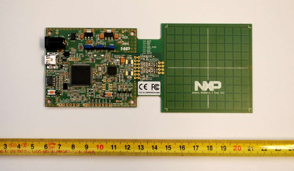
OWRPNEV5180B
Dec 23, 2015PN8180 Customer Evaluation Board
Equipment Class
DXX - Part 15 Low Power Communication Device Transmitter
OWROM5569-NT322E
Dec 16, 2015NTAG I2C plus Explorer Kit
Equipment Class
DXX - Part 15 Low Power Communication Device Transmitter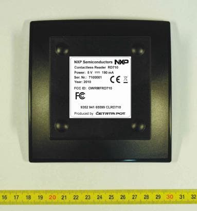
OWRMFRD710
May 09, 2011Contactless Reader
Equipment Class
DXX - Part 15 Low Power Communication Device Transmitter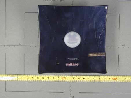
OWR40089
Mar 21, 2002MIFARE Contactless Card Reader
Equipment Class
DXX - Part 15 Low Power Communication Device Transmitter
OWRICODE-SLEV900
Jul 09, 2000RFID Tag
Equipment Class
DXX - Part 15 Low Power Communication Device Transmitter