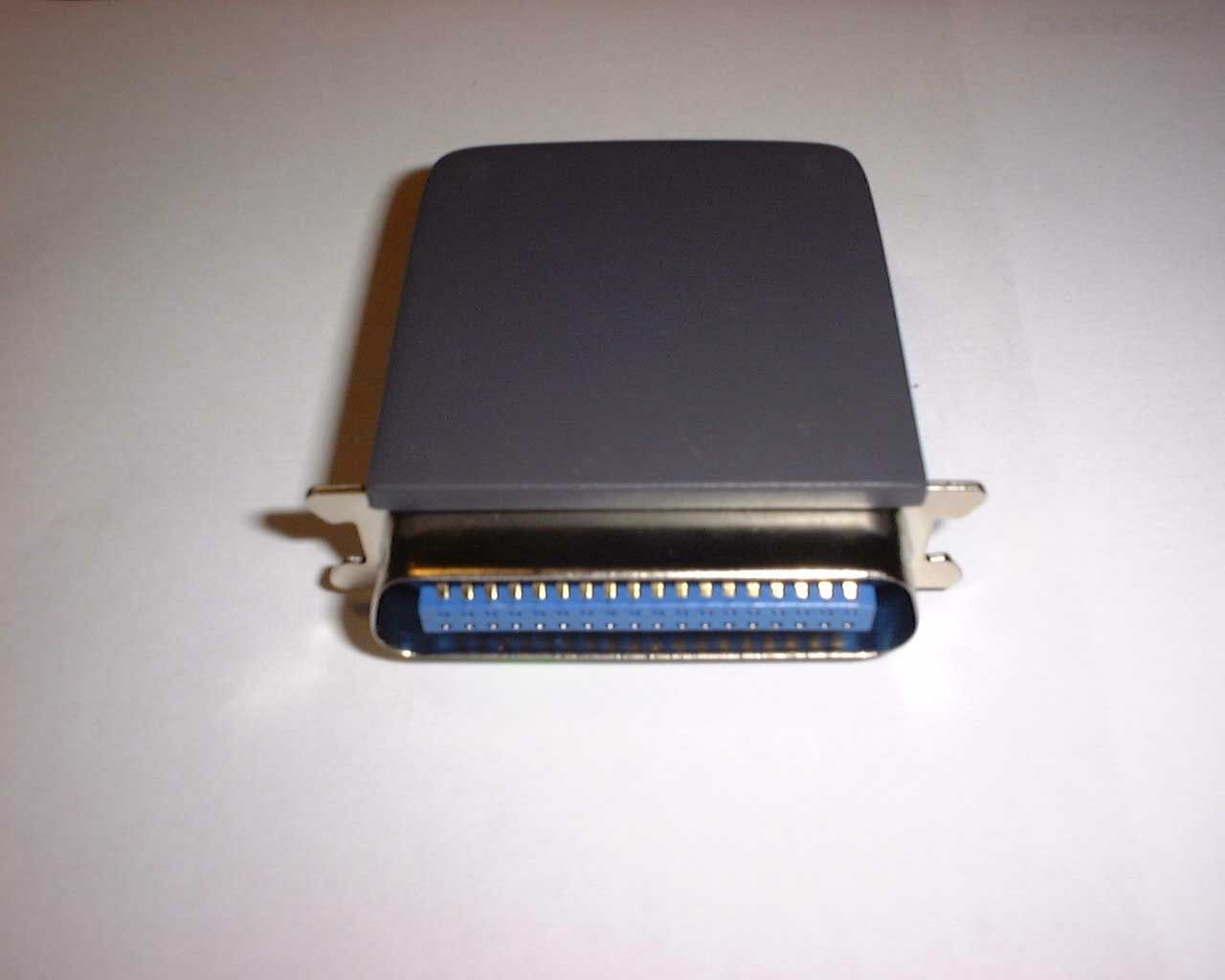
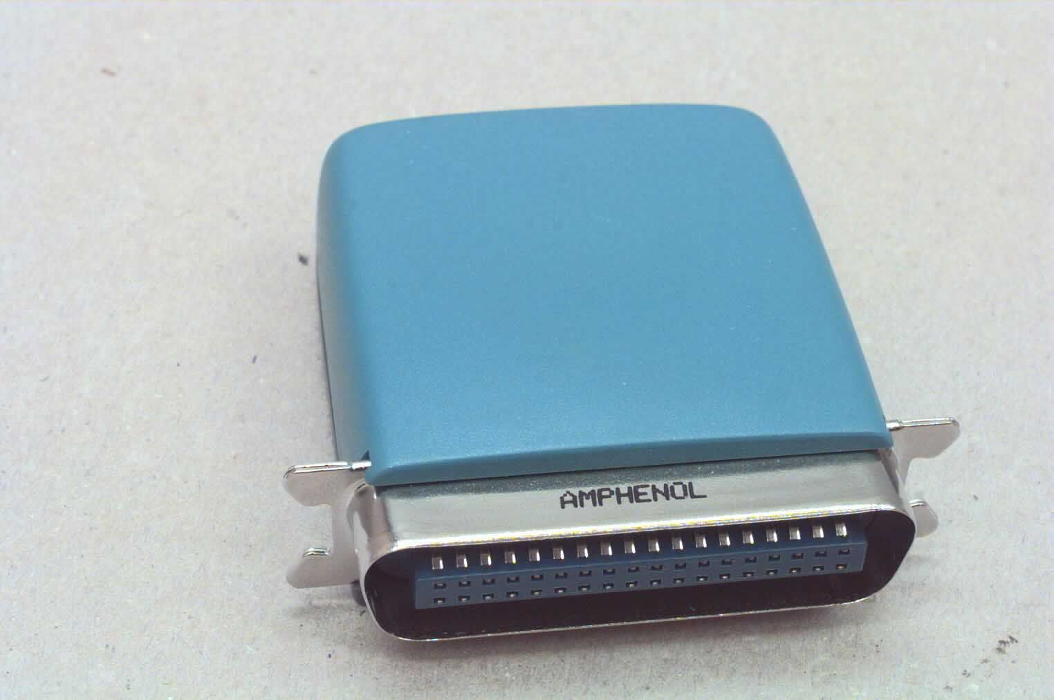
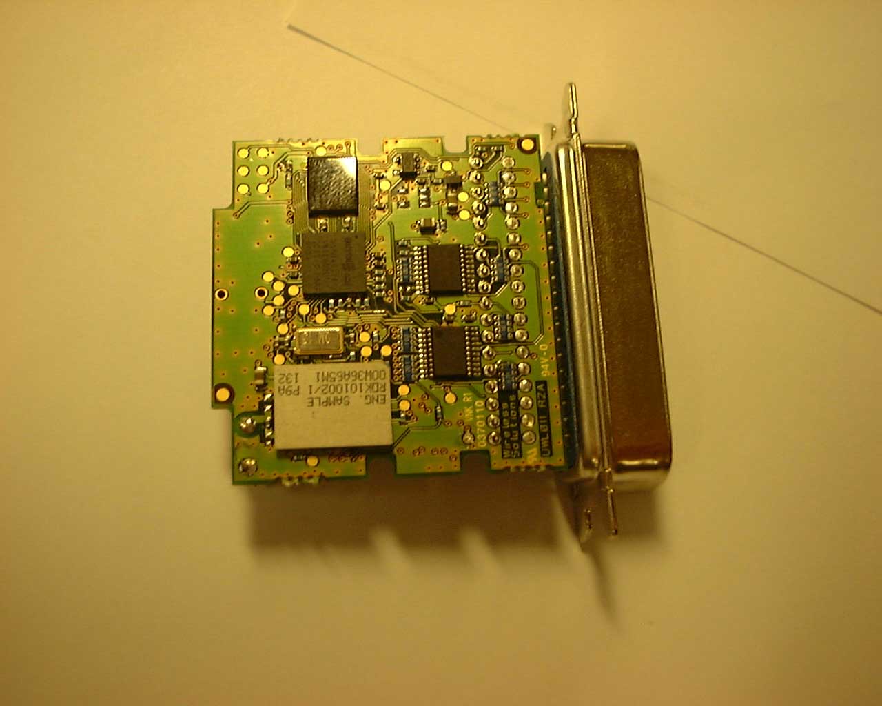
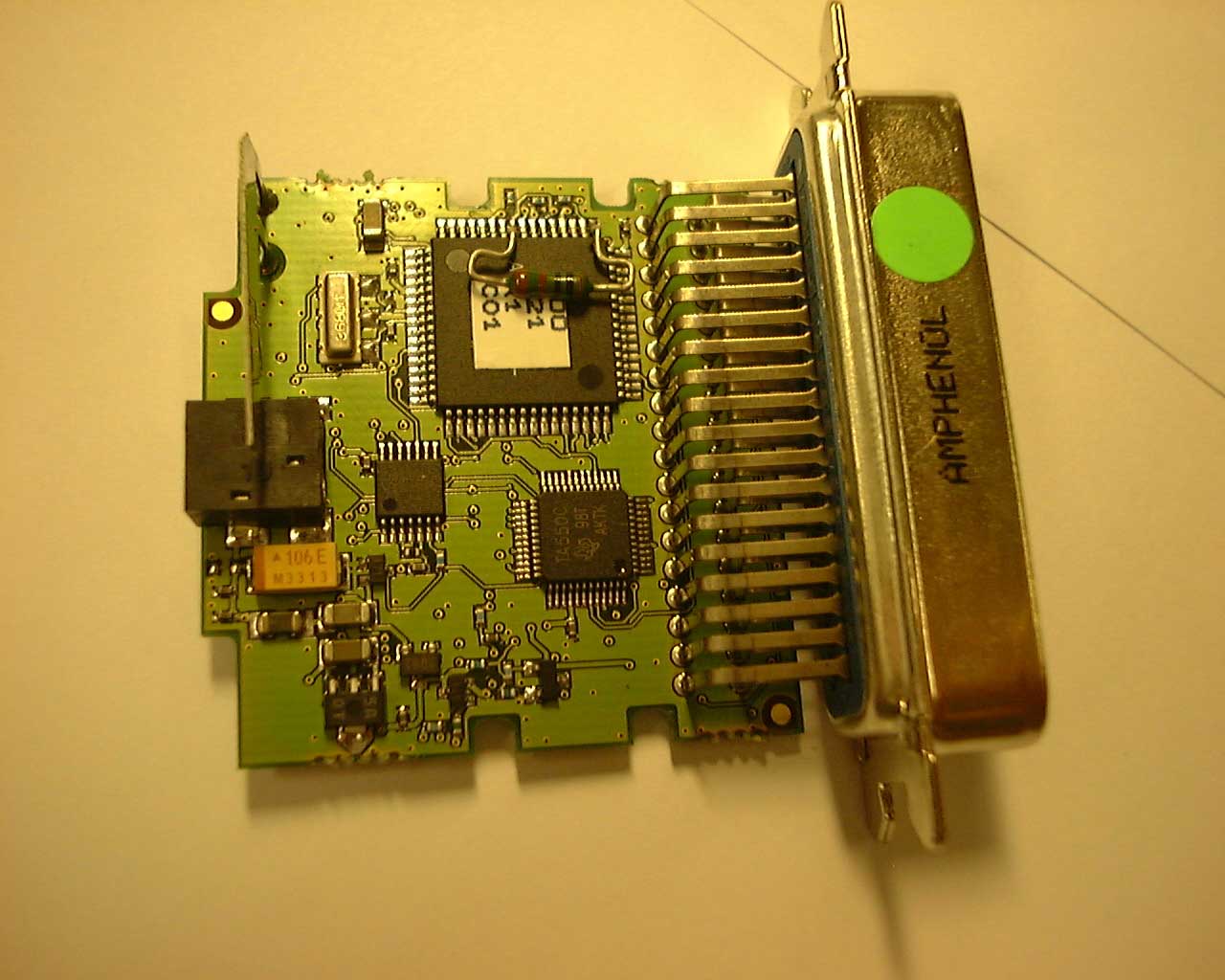
OXTLSE019Proprietary wireless printer module
National Semiconductor Sweden AB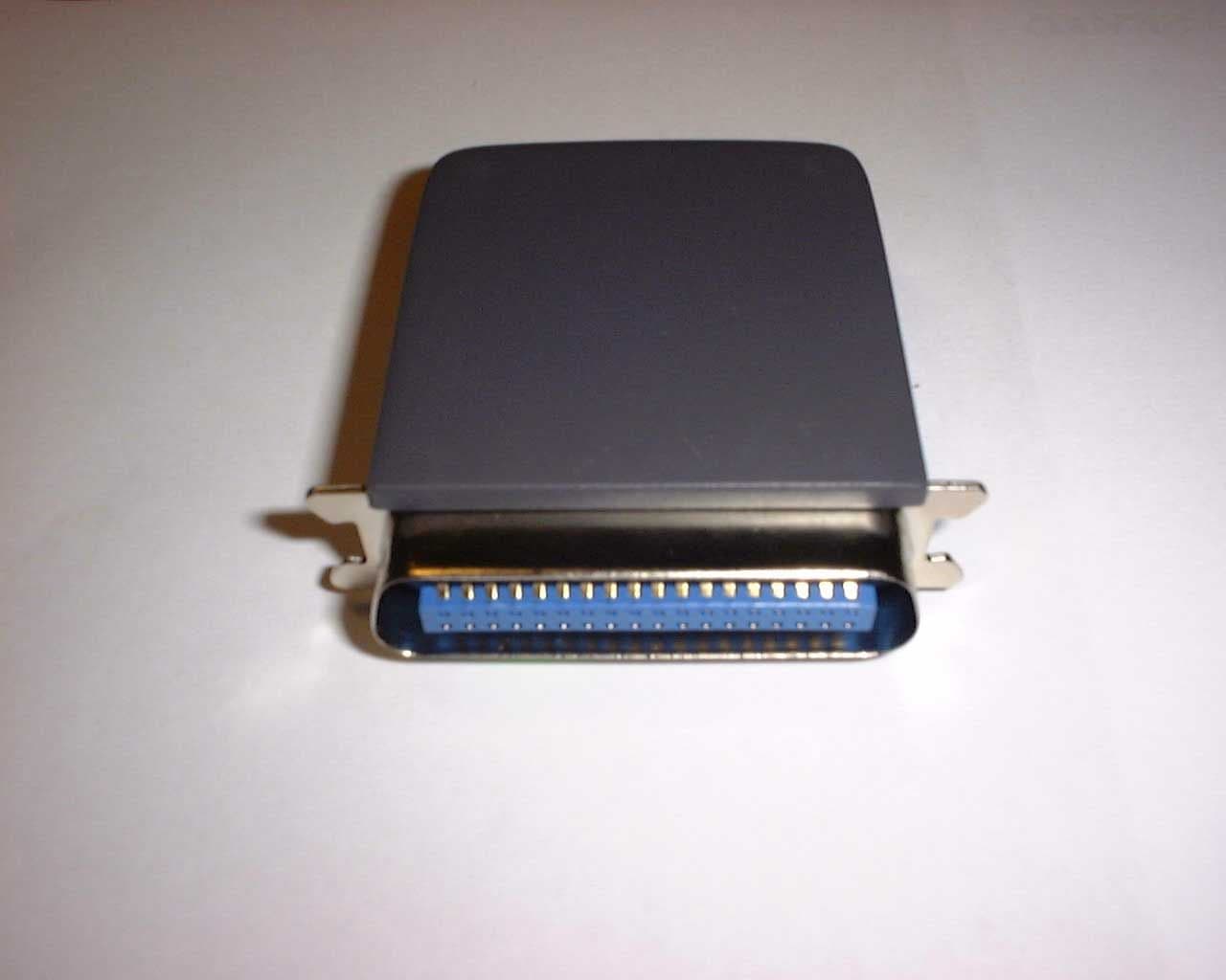
Click to zoom
Application Details
- Equipment Class
- DSS - Part 15 Spread Spectrum Transmitter
- Date of Grant
- Mar 22, 2001
- Application Purpose
- Original Equipment
- Date of Application
- Mar 22, 2001
- Equipment Note
- Proprietary wireless printer module
- Frequency Range
- 2402.00000000 - 2480.00000000
- Country
- Sweden
Documents & Files
Document Text
Text extracted from the exhibit documents filed with the FCC. Open a document above to read the original.
Users Manual
Users Manual / Printer Adapter1 (10) Uppgjord (även faktaansvarig om annan) - Prepared (also subject responsible if other) Nr - No. Mikael Ohlsson19817/LSE019 Dokansv/Godk - Doc respons/Approved Kontr - Checked Datum - Date RevFile 2000-08-17PA1141494 USER’S MANUAL LSE 019 Printer Adapter Bluetooth Disclaimer: This manual is published by Wireless Solutions Sweden AB , without any warranty. Improvements and changes to this manual necessitated by typhographical errors, inaccuracies of current information, or improvements to equipment, may be made by Wireless solutions Sweden AB at any time and without notice. Such changes will however be incorporated into new editions of this manual. Copyright 2000 Wireless Solutions Sweden AB Users Manual / Printer Adapter2 (10) Uppgjord (även faktaansvarig om annan) - Prepared (also subject responsible if other) Nr - No. Mikael Ohlsson19817/LSE019 Dokansv/Godk - Doc respons/Approved Kontr - Checked Datum - Date RevFile 2000-08-17PA1141494 TABLE OF CONTENTS 1ABBREVIATIONS.............................................................................................................................. 2 2DESCRIPTION.................................................................................................................................... 3 2.1 IN TRO DUCTIO N ................................................................................................................................................................... 3 2.2 PRODUCT DESCRIPTION ....................................................................................................................................................... 3 3BLUETOOTH STANDARD INFORMATION...................................................................................... 3 3.1B LUETO O TH C APABILITY S TATEMEN T ................................................................................................................................. 3 4INSTALLATION AND CONNECTION PROCESS FOR THE PRINTER ADAPTER............................. 4 4.1I NSTRUCTIONS FOR INSTALLING THE PRINTER ADAPTER FROM A NY C OM ............................................................................. 4 5TROUBLE SHOOTING ....................................................................................................................... 5 6TECHNICAL SPECIFICATION ........................................................................................................... 5 7REGULATIONS .................................................................................................................................. 6 7.1E UROPEAN COMPLIANCE .................................................................................................................................................... 6 7.2FCC (US) COMPLIANCE ..................................................................................................................................................... 7 7.3E XPOSURE TO R ADIO F REQUENCY R ADIATION .................................................................................................................... 8 7.4 IMPORTANT SAFETY INFORMATION ..................................................................................................................................... 8 7.4.1SAFETY WARNINGS ! ........................................................................................................................................... 8 7.4.2Operating Environment.............................................................................................................................................. 9 1 ABBREVIATIONS ISM Industrial, Scientific and Medical AC Alternate Current DC Direct Current LED Light Emmitting diode PWM Pulde Width Modulation PCM Pulse Code Modulation FCC Federal Communications Commission ETS European Telecommunication Standard UL Undewriters Laboratories CTR Common Technical Regulations ETL Edison Testing Laboratory ETSI European Telecommunications standards Institute EEC European Economic Community EMC Electromagnetic Compatibilty LVDLow voltage directive SIGSpecial Intrest Group Users Manual / Printer Adapter3 (10) Uppgjord (även faktaansvarig om annan) - Prepared (also subject responsible if other) Nr - No. Mikael Ohlsson19817/LSE019 Dokansv/Godk - Doc respons/Approved Kontr - Checked Datum - Date RevFile 2000-08-17PA1141494 2 DESCRIPTION 2.1 INTRODUCTION This users manual covers the LSE 019 Printer adapter for wireless printing applications. The Printer Adapter supports Wireless Printing when used in conjunction with the LSE 041 Bluetooth Bluecard. The Printer Adapter provides a parallell interface to a printer. The maximum distance for error free printing is up to 10 meters. A PC based printer installation is required. 2.2 PRODUCT DESCRIPTION The LSE019 Printer Adapter adapter provides wireless printing for Bluetooth applications in the 2.4 GHz ISM band. The Printer Adapter is intended for insert into a printer parallel port. LSE019 Features: • Data rates up to 460 Kbps. • Act as one device in a Bluetooth network. • Proprietary wireless printing supported. LSE019 Applications: • Wireless printing. 3 BLUETOOTH STANDARD INFORMATION 3.1 B LUETOOTH C APABILITY S TATEMENT This product is manufactured to meet the Bluetooth specification 1.0A. The following profiles / interoperable products are supported: • Generic Access Profile Note! The Wireless Printing Profile is an ow n profile and the the Printer Adapter w orks only in conjunction w ith the LSE 041 Bluetooth Bluecard. T his profile must never be referred to in any w ay as beeing a Bluetooth standard profile. Users Manual / Printer Adapter4 (10) Uppgjord (även faktaansvarig om annan) - Prepared (also subject responsible if other) Nr - No. Mikael Ohlsson19817/LSE019 Dokansv/Godk - Doc respons/Approved Kontr - Checked Datum - Date RevFile 2000-08-17PA1141494 4 INSTALLATION AND CONNECTION PROCESS FOR THE PRINTER ADAPTER 4.1 I NSTRUCTIONS FOR INSTALLING…
Text truncated - open the document above for the full version.
Attestation Statements
Hop Selection29 November 1999127 BLUETOOTH SPECIFICATION Version 1.0 Bpage 127 of 1082 Baseband Specification 11 HOP SELECTION In total, 10 types of hopping sequences are defined − five for the 79-hop and five for the 23-hop system, respectively. Using the notation of parentheses () for figures related to the 23-hop system, these sequences are: •A page hopping sequence with 32 (16) unique wake-up frequencies dis- tributed equally over the 79 (23) MHz, with a period length of 32 (16); •A page response sequence covering 32 (16) unique response frequencies that all are in an one-to-one correspondence to the current page hopping sequence. The master and slave use different rules to obtain the same sequence; •An inquiry sequence with 32 (16) unique wake-up frequencies distributed equally over the 79 (23) MHz, with a period length of 32 (16); •A inquiry response sequence covering 32 (16) unique response frequen- cies that all are in an one-to-one correspondence to the current inquiry hop- ping sequence. •A channel hopping sequence which has a very long period length, which does not show repetitive patterns over a short time interval, but which dis- tributes the hop frequencies equally over the 79 (23) MHz during a short time interval; For the page hopping sequence, it is important that we can easily shift the phase forward or backward, so we need a 1-1 mapping from a counter to the hop frequencies. For each case, both a hop sequence from master to slave and from slave to master are required. The inquiry and inquiry response sequences always utilizes the GIAC LAP as lower address part and the DCI (Section 5.4 on page 73) as upper address part in deriving the hopping sequence, even if it concerns a DIAC inquiry. 11.1 GENERAL SELECTION SCHEME The selection scheme consists of two parts: • selecting a sequence; • mapping this sequence on the hop frequencies; The general block diagram of the hop selection scheme is shown in Figure 11.1 on page 128. The mapping from the input to a particular hop frequency is per- formed in the selection box. Basically, the input is the native clock and the cur- rent address. In CONNECTION state, the native clock (CLKN) is modified by an offset to equal the master clock (CLK). Only the 27 MSBs of the clock are used. In the page and inquiry substates, all 28 bits of the clock are used. How- ever, in page substate the native clock will be modified to the master’s estimate of the paged unit. 12829 November 1999Hop Selection BLUETOOTH SPECIFICATION Version 1.0 Bpage 128 of 1082 Baseband Specification The address input consists of 28 bits, i.e., the entire LAP and the 4 LSBs of the UAP. In CONNECTION state, the address of the master is used. In page sub- state the address of the paged unit is used. When in inquiry substate, the UAP/LAP corresponding to the GIAC is used. The output constitutes a pseudo- random sequence, either covering 79 hop or 23 hops, depending on the state. Figure 11.1: General block diagram of hop selection scheme. For the 79-hop system, the selection scheme chooses a segment of 32 hop frequencies spanning about 64 MHz and visits these hops once in a random order. Next, a different 32-hop segment is chosen, etc. In case of the page, page scan, or page response substates, the same 32-hop segment is used all the time (the segment is selected by the address; different units will have dif- ferent paging segments). In connection state, the output constitutes a pseudo- random sequence that slides through the 79 hops or 23 hops, depending on the selected hop system. For the 23-hop systems, the segment size is 16. The principle is depicted in Figure 11.2 . Figure 11.2: Hop selection scheme in CONNECTION state. SELECTION BOX hop frequency UAP/LAP 23/79 mode CLOCK 27 28 04662642 781 737577 segment 1 segment 2 segment 3 ∆ Europe/US Japan/France/Spain 79 23 32 16 16 8 segment length# of hops ∆ Hop Selection29 November 1999129 BLUETOOTH SPECIFICATION Version 1.0 Bpage 129 of 1082 Baseband Specification 11.2 SELECTION KERNEL The hop selection kernels for the 79 hop system and the 23 hop system are shown in Figure 11.3 on page 129 and Figure 11.4 on page 129, respectively. The X input determines the phase in the 32-hop segment, whereas Y1 and Y2 selects between master-to-slave and slave-to-master transmission. The inputs A to D determine the ordering within the segment, the inputs E and F determine the mapping onto the hop frequencies. The kernel addresses a register containing the hop frequencies. This list should be created such that first all even hop fre- quencies are listed and then all odd hop frequencies. In this way, a 32-hop seg- ment spans about 64 MHz, whereas a 16-hop segment spans the entire 23-MHz. Figure 11.3: Block diagram of hop selection kernel for the 79-hop system. Figure 11.4: Block diagram of hop selection kernel for the 23-hop system. X O R XOR 55 XADD mod32 AB 4 5 5 5 ADD EF 7 7 7 0 2 4 CD 5 9 5 Y1 Y2 mod 79 1 78 3 77 PERM5 X O R XOR ADD AB 45 ADD EF 77 0 2 4 CD 5 9 5 Y1 Y2 X 4 mod16 mod 23 22 1 3 21 4445 PERM4 13029 November 1999Hop Selection BLUETOOTH SPECIFICATION Version 1.0 Bpage 130 of 1082 Baseband Specification The selection procedure consists of an addition, an XOR operation, a permuta- tion operation, an addition, and finally a register selection. In the remainder of this chapter, the notation A i is used for bit i of the BD_ADDR. 11.2.1 First addition operation The first addition operation only adds a constant to the phase and applies a modulo 32 or a modulo 16 operation. For the page hopping sequence, the first addition is redundant since it only changes the phase within the segment. How- ever, when different segments are concatenated (as in the channel hopping sequence), the first addition operation will have an impact on the resulting sequence. 11.2.2 XOR operation Let Z’ denote the output of the first addition. In the XOR operation, the four LSBs of Z’ are modulo-2 added to the address bits A 22-19 . The operation is illustrated…
Text truncated - open the document above for the full version.
Attestation Statements
2.1033(b)(10) Receiver input bandwidth, synchronization and repeated single or multiple packets: The input bandwidth of the receiver is 1 MHz. In every connection, one Bluetooth device is the master and the other one is the slave. The master determines the hopping sequence. The slave follows this sequence. Both devices shift between RX and TX time slot according to the clock of the master. Additionally the type of connection (e.g. single or multi-slot packet) is set up at the beginning of the connection. The master adapts its hopping frequency and its TX/RX timing is according to the packet type of the connection. Also, the slave of the connection uses these settings. Repeating of a packet has no influence on the hopping sequence. The hopping sequence generated by the master of the connection will be followed in any case. That means, a repeated packet will not be send on the same frequency, it is send on the next frequency of the hopping sequence
Block Diagram
CONFIDENTIAL Description1(1) Uppgjord (även faktaansvarig om annan) -Nr – No WSS Tomas Blom1551-SPB030 Dokansv/Godk - Doc respons/ApprovedKontr - CheckedDatum - DateRevFile WSS Tomas Blom2001-02-28 A1551_SPB030_B \\ASESU001\PROJECTS\P010_BT_Application\documents\1551 Product Description\1551_SPB030_B.doc 1 Block Diagram IC11 Radio IC17 Baseband IC19 Flash Printer Connector IC4 UART Interface IC8 uProcessor 5V/3.3V Supply 2.8V Supply External Supply X2 X1*2 Prin- ter Inter- face 2.402- 2.480GHz 13MHz 3.68MHz 7.36MHz 2 Circuit Description There is a 3.68 MHz clock generated by IC8 and X1. This clock is used by CPU IC8. This clock is frequency doubled in IC3 for use also as baudrate clock by UART IC4, max UART speed is 460 kbps. The radio IC11 is using the 13MHZ reference X2. Power to the card is supplied at Power Connector P3. It is regulated in IC6 to 5.0 volts and in IC7 to 3.3 volts. IC18 regulates from 3.3 to 2.8 volts for the BT-radio parts IC11, IC17 and IC19. IC18 is shut on/off under program control via signal BTON. Power to Printer Interface circuits IC1-3 is fed via a diode in D3 from 5 volt, (=IC6 out) There is a CPU, IC8, with an external UART, IC4, as link to the BT-parts. The antenna is a standing PIFA (Planar Inverted F Antenna) type antenna with 0dBi gain.
Cover Letter(s)
FCC Response Uppgjord (även faktaansvarig om annan) - Prepared (also subject responsible if other)Nr - No. WSS Mikael Ohlsson Dokansv/Godk - Doc respons/ApprovedKontr - CheckedDatum - DateRevFile 2001-02-28A FCC Approval, LSE019 and LSE041 Response to the review remarks for OXTLSE019 and OXTLSE041. 1. Block diagram including circuit description attached. 2. Block diagram attached. The block diagram in the Ericsson description is separately attached. 3. According to the Ericsson data sheet, ROK 101 007, page 5, the 15.247 input bandwidth requirement is specified under RF-Specifications as “Double-sided IF Bandwidth” and equal with the input bandwidth (Spec. 1 MHz). The information received from Ericsson is that the ROK 101 007 Bluetooth Module is an alternative to the FCC-approved Bluetooth module, FCC-identifier: CGK8001001, and will be FCC approved soon, with the above mentined Bluetooth module approval as basis. 4. Description of the antenna type for each device are provided in the Block diagram/Circuit Description. 5. The “part 15” on the marking is deleted. Revised marking doc. Is attached. Since the devices/marking labels are to small to place the required text according to part 15.19(a) (3),The information required by this paragraph is already placed in the users manual. This will be FCC accepted according to part 15.19(a) (5). The following text can be seen in the User’s Manual for OXTLSE019 and OXTLSE041: This device complies with Part 15 of the FCC rules. Operation is subject to the following two conditions: (1) this device may not cause harmful interference, and (2) this device must accept any interference received, including interference that may cause undesired operation. 6. The hypen between OXT-LSE019 and OXT-LSE041 is deleted on the marking labels. 7. The PC-card, OXTLSE041 have to be seen as a modular approval, it is not intended for only the Toshiba computer, it was only used as test platform. As far as I can see, the PC-card fulfills the criteria for modular approval (own RF-shielding, own power supply regulation, permanently affixed antenna, stand-alone test report, own FCC-label etc.) The PC-card tested with the Toshiba computer as a platform must not be seen as a system. The PC-cars is a unique product. Best regards, Mikael Ohlsson Product Certification Wireless Solutions Sweden AB Rissneleden 138, plan 6 S-174 02 Sundbyberg, Sweden Phone: +46 8 7337651 Mobile: +46 733 604044 E-mail: [email protected]
Cover Letter(s)
From: Raymond Laforge [[email protected]] Sent: Monday, January 22, 2001 10:53 AM To: [email protected] Subject: Re: TCB review of 15.247 device more Both of the devices described would be approved by the Commission as a limited modular transmitter. By limited, I mean it would have some restrictions/conditions listed on the Grant of Equipment Authorization. The TCB may process these devices if they believe there are no RF safety issues involved in the processing of the devices. >>> <[email protected]> 12/22/00 03:29PM >>> Dear Sir: We have been asked to review two 1 mW EIRP Bluetooth devices: 1) PC adapter, for wireless connection to remote printer. It is a PC card for an internal PC card slot, with built-in antenna. 2) Printer adapter, attaches to a printer's parallel port. It has an integral antenna. Both devices are below the EIRP limits in the TCB exclusion list of December 18, 2000 (section VI, paragraph e.vii.1). However, the same exclusion list disqualifies 15.247 transmitters which "operate as a module, including those that are installed in, or attached, to another product" (section VI, paragraph e.iii). While neither of these devices qualifies as a module per FCC Interpretation Letter #1105, each is intended to be "installed in, or attached to, another product." May a TCB certify these devices? Thank you, Roland Gubisch ITS
Cover Letter(s)
FCC ID: OXTLSE019 Part 15 Unlicensed Modular Transmitter Approval Justification per DA 00-1407, released: June 26, 2000 re quire me ntre fe re nce 1The modular transmitter must have its ow n RF shielding. Relevant emission requirements are met without additional shielding. See external photos . 2The modular transmitter must have buffered modulation/data inputs All inputs to the modules are buffered through logic or microprocessor inputs. S e e sc he ma t ic d ia g ra ms . 3The modular transmitter must have its own pow er supply regulation. All power lines derived from the host device are regulated before energizing other circuits internal to the EUT. Se e sche matic diag ra ms. 4The modular transmitter must comply with the antenna requirements of Section 15.203 and 15.204(c). The EUT has a built-in antenna, which is inaccessible to the user. 5The modular transmitter must be tested in a stand-alone configuration, i.e., the module must not be inside another device during testing. The EUT attaches to an external printer parallel port. This configuration provides no RF shielding. 6The modular transmitter must be labeled with its own FCC ID number, and, if the FCC ID is not visible when the module is installed inside another device, then the outside of the device into which the module is installed must also display a label referring to the enclosed mod ule. The EUT carries an FCC ID label whose artwork and label position are clearly indicated; see Ma rking and Label Position exhibits. The EUT and the label are visible when installed. 7The modular transmitter must comply with any specific rule or operating requirements applicable to the trans mi tter a nd the manufacturer must provide adequate instructions along with the module to explain any such requirements. A copy of these instructions must be included in the application for equipment authorization. The EUT incorporates a certified Bluetooth module FCC ID: CGK8001001, whose 15.247 spread spectrum frequency hopping functional parameters cannot be altered by the user. See Bluetooth mo dule de scri pt io n . 8The modular transmitter must comply with any applicable RF exposure requirements. For example, FCC Rules in Sections 2.1091, 2.1093 and specific Sections of Part 15, including 15.319(i), 15.407(f), 15.253(f) and 15.255(g), require that Unlicensed PCS, UNII and millimeter wave devices perform routine environmental evaluation for RF Exposure to demonstrate compliance. In addition, spread spectrum transmitters operating under Section 15.247 are required to address RF Exposure compliance in accordance with Section 15.247(b)(4). RF output is 1 mW, w hich complies with the conditions of use of FCC ID: CGK8001001, and constitutes no RF e xpos ure ha zard w he n not co- located with another transmitter. User precautions are provided in the User Manual to avoid contact with the EUT during operation.
ID Label/Location Info
Marking Label for Wireless Solutions Sweden AB “Blue Card”, Model No. LSE 041 Marking Label for Wireless Solutions Sweden AB “Printer Module”, Model No. LSE 019 E TL- Lis te d. C onfo rms to A N SI/U L 1950 FCC ID(P art 15): OX T- LS E 041 B D address xxxxxxxx Model. No. LS E 041 RRR xxxxxxx Serial.N o. xxxxxxxxxxxx ETL-Listed. Conforms to ANSI/UL 1950 FCC ID(Part 15): OXT-LSE019 BD address xxxxxxxx Model. No. LSE 019 RRR x xxxx xx Serial.No. xx xxxxxxxx
ID Label/Location Info
Marking instruction LSE0191(1) Uppgjord (även faktaansvarig om annan) -Nr – No WSS Mikael Ohlsson19817-LSE019 Dokansv/Godk - Doc respons/ApprovedKontr - CheckedDatum - DateRevFile 2000-12-0730 PA3 D:\Ready _To_Convert\Doc\141506.DOC Label marking instruction 1 Revision history DateRevNote 2000-09-07PA1Creation 2 Abstract • This document gives instruction on how to mark the LSE 019 product. 3 Label The type label shall be placed according to the figure below: TEXT PLACE LABEL CENTERED +/-0.5mm PRINTER ADAPTER BOTTOM VIEW PLACE LABEL HERE. TEXT ORIENTATION AS IN THE PICTURE 10mm+/-1mm
Operational Description
Bluetooth LSE 019 Printer Adapter LSE 019 Printer Adapter, Revision R1D: The “LSE 019 printer adapter” is a proprietary wireless printer module that provides a parallel interface to a printer. This adapter works with Bluetooth products that supports WSS proprietary wireless printing (patent pending). The maximum distance for error free printing is up to 10 m, a PC based printer installation is required. Features: • Bluetooth V1.0B + Critical Errata compliant • Upgradeable to V1.1 specification • Parallel Centronics printer interface • Data rates up to 460 kbs • WSS Proprietary wireless printing supported • The antenna is integrated into the Printer module Application Profiles: • Generic Access profile • WSS Proprietary wireless printing The LSE 019 Printer Adapter is certified by the Bluetooth SIG and compliant with the Bluetooth 1.0B specification. The Printer Adapter is designed to comply with the Bluetooth 1.1 Draft specification. Further moore, the product complies with the regulatory national requirements (safety, EMC and radio type approval) according to the “Wireless Solutions Product Approval sheet” appendix A. WSS stands for Wireless Solutions Sweden AB Note! Bluetooth is a trade mark owned by Telefonaktiebolaget L M Ericsson, Sweden and licensed to Wireless Solutions Sweden AB. www.wireless.se [email protected] Technical Specification, LSE 019 Printer Adapter: Radio Specifications: Frequency range2.402 – 2.4800 GHz Programmable for specific national regulations Supported SpecificationBluetooth 1.0B specification RF output power0 dBm, Power Class 3 Power managementActive and passive power saving modes Receiver sensitivityBetter than -70 dBm at 0.1% BER Frequency spectrum utilizationFrequency Hopping Spread Spectrum (FHSS) ModulationGaussian Frequency Shift Keying (GFSK) Bit-rate1 Mbs AntennaIntegrated Regulative complianceFCC part 15, UL 1950 (US), ETS 300 328, ETS 300 826, EN 60 950 (EUROPE). Electrical Characteristics: Power supply+ 5V external or from printer pin 18 Max power consumption70 mA Min power consumption40 mA Physical interfaceCentronics connector Visual indicatorsPower (LED) Data traffic (LED) Security: Initialization4 digit PIN code AuthenticationSecurity mode 2 supported EncryptionSupported Mechanical Specifications: Physical dimensions50 x 60 x 19 mm Environment: Operating temperature0 to 55°C Storage temperature-20 to 70°C Humidity5 – 95% non condensing Configuration: Drivers, set-up and configurationVia a PC connected adapter Software maintainability: Printer Adapter software upgradeVia a PC connected adapter Appendix A Wireless Solutions Sweden AB Product Approval Sheet The LSE 019 Printer Adapter is tested and compliant with the national regulatory requirements according to the standards mentioned below. European Union: • EMCETS 300 826 (EMC standard for 2,4 GHz wide band transmission systems and hiperlan) • RadioETSI EN 300 328-1 (EMC and radio spectrum matters for 2,4 GHz ISM band) • SafetyEN 60 950 (Safety of Information technology equipment) Compliance with this standards covering essential requirements under the 1999/5/EG R&TTE directive is necessary for placing the product on the EU market. U.S / Canadian market: • EMCFCC CFR47 part 15.C (Emission requirements for product operating within 2.4 GHz ISM band) • RadioFCC CFR47 part 15.247 (Radio spectrum requirements for FHSS systems operating within the 2.4 GHz ISM band) • SafetyUL 1950 (Safety of information technology equipment) Compliance with this standards, UL-listing and FCC-registration is necessary for placing the product on the U.S / Canadian market.
Operational Description
CONFIDENTIAL Description1(1) Uppgjord (även faktaansvarig om annan) -Nr – No WSS Tomas Blom1551-SPB030 Dokansv/Godk - Doc respons/ApprovedKontr - CheckedDatum - DateRevFile WSS Tomas Blom2001-02-28 A1551_SPB030_B \\ASESU001\PROJECTS\P010_BT_Application\documents\1551 Product Description\1551_SPB030_B.doc 1 Block Diagram IC11 Radio IC17 Baseband IC19 Flash Printer Connector IC4 UART Interface IC8 uProcessor 5V/3.3V Supply 2.8V Supply External Supply X2 X1*2 Prin- ter Inter- face 2.402- 2.480GHz 13MHz 3.68MHz 7.36MHz 2 Circuit Description There is a 3.68 MHz clock generated by IC8 and X1. This clock is used by CPU IC8. This clock is frequency doubled in IC3 for use also as baudrate clock by UART IC4, max UART speed is 460 kbps. The radio IC11 is using the 13MHZ reference X2. Power to the card is supplied at Power Connector P3. It is regulated in IC6 to 5.0 volts and in IC7 to 3.3 volts. IC18 regulates from 3.3 to 2.8 volts for the BT-radio parts IC11, IC17 and IC19. IC18 is shut on/off under program control via signal BTON. Power to Printer Interface circuits IC1-3 is fed via a diode in D3 from 5 volt, (=IC6 out) There is a CPU, IC8, with an external UART, IC4, as link to the BT-parts. The antenna is a standing PIFA (Planar Inverted F Antenna) type antenna with 0dBi gain.
RF Exposure Info
From:Annika Nyberger ITS/ES-Sto Sent:Wednesday, February 14, 2001 8:43 AM To:Roland G ubisch ITS/ES-Box Cc:Björ n Rosenquist ITS/ES-Sto Subject:Supplementing of RF exposure info. from Wireless Solutions AB Dear Roland, Here comes an RF exposure calculation for Wireless Solutions Bluetooth products LSE 041 and LSE 019. I hope you can complete this file with the earlier issued files. Radiation Bluetooth.pdf I also have a question about a HiperLAN / 2 WLAN product which works in the following frequency ranges 5150-5350 MHz and 5725-5825 MHz ( U-NII band). The system consists of a base station and a terminal adapter (type PC-card type 2 (card bus)). The output power (EIRP) is max 200 mW (23 dBm). The modulation schedule for H2 is OFDM (Orthogonal frequency division multiplexing). My question is: are the FCC requirements for this type of WLAN product the same as for WLAN products which work in 2.4 GHz (15.247) ? If yes, can we than use your earlier issued evaluation form: cert15247r3.doc version 1.3 ? If not, please could you help us with some information about this case. Thanks in advance ! Best Regards Annika Nyberger
Test Setup Photos
Set up photos: Bluetooth Printer adapter LSE 019 Mains terminal conducted emission 0,45 – 30 MHz, Rear side: Mains terminal conducted emission 0,45 – 30 MHz, Front side: Radiated emission 30 MHz – 26 GHz, Rear side: Radiated emission 30 MHz – 26 GHz, Front side:
Contact Information
Applicant
Mikael Ohlsson(Project engineer)
Technical Contact
Wireless Solutions Sweden ABMikael Ohlsson
[email protected]46-8-7337651
Rissneleden 138, floor 6 · Sundbyberg · Sweden
Non-Technical Contact
Wireless Solutions Sweden ABMikael Ohlsson
[email protected]46-8-7337651
Test Firm
Intertek SEMKO ABNiklas Bostrom
Technical Specifications
| # | Rule Parts | Frequency Range | Power Output | Tolerance |
|---|---|---|---|---|
| 1 | 15C | 2.40 GHz - 2.48 GHz | 1.00 mW | 0.0031250000 % |
Other Applications from National Semiconductor Sweden AB
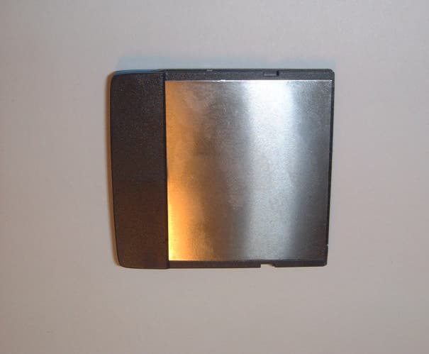
OXTLSE039R2
May 30, 2002Compact Flash Card Interface to Bluetooth
Equipment Class
DSS - Part 15 Spread Spectrum Transmitter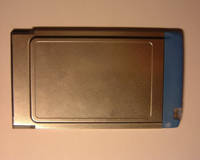
OXTLSE041R2
Apr 16, 2002Bluetooth PC card for Host
Equipment Class
DSS - Part 15 Spread Spectrum Transmitter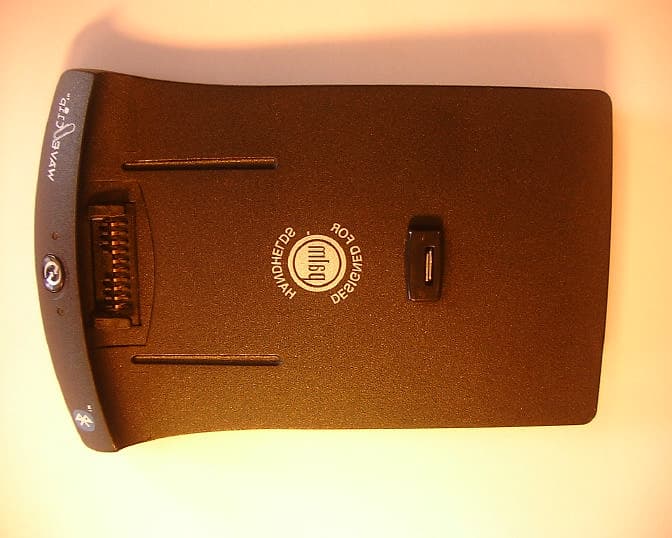
OXTLSE044
Nov 25, 2001Bluetooth Adapter for Palm V Handhelds
Equipment Class
DSS - Part 15 Spread Spectrum Transmitter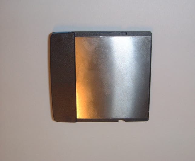
OXTLSE039
Aug 08, 2001PCMCIA Bluetooth Interface
Equipment Class
DSS - Part 15 Spread Spectrum Transmitter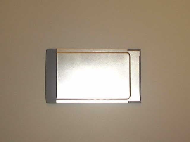
OXTLSE041
Mar 22, 2001PCMCIA card for host enabled Bluetooth devices
Equipment Class
DSS - Part 15 Spread Spectrum Transmitter